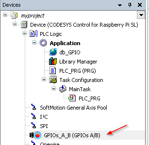
Open your project, and Click on the GPIOs_A_B item.
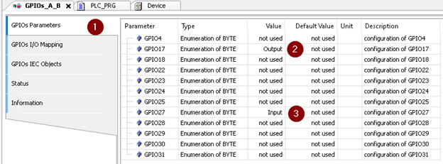
Click on the GPIOs Parametres, you can assign the function of each pins to be Input,Output or not used.
In this example, I chose GPIO17 to be Output and GPIO27 to be Intput.
Here is the layout of Rasperry GPIOs.

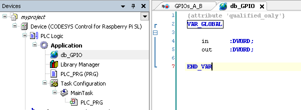
Create a Global Variable List, and define in,out variables as DWORD.
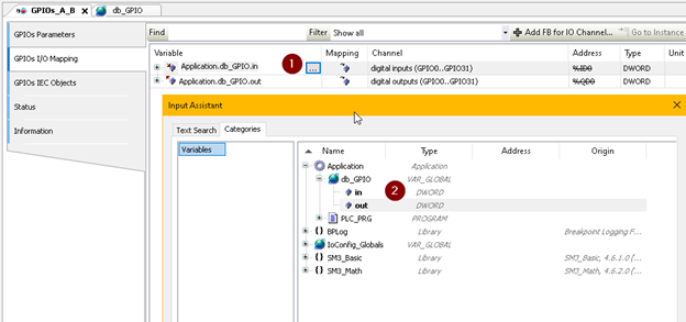
Go back to the GPIOs_A_B view and click the GPIOs Mapping. you can see a … Button . Click it and assign the digital inputs / outputs to the Variables that you defined above.
In the first step, we assign Pin17 to be Output. Let create a sample program to test the function.
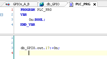
In the PLC_PRG, define a Bool variable that named as On and assign the value of this variable directly to Pin17.
While variable “On” is True, use your tester to measure the voltage between Pin17 and GND, there is 3.3.v.
Byebye!