In this article I will describe the HMI functionality of in Selmo Studio. Codesys was used in the article, but the operation is the same in TwinCAT and CtrlX.
Let’s get started.
Reference Link
Implementation
Configure HMI Text
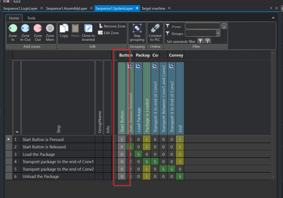
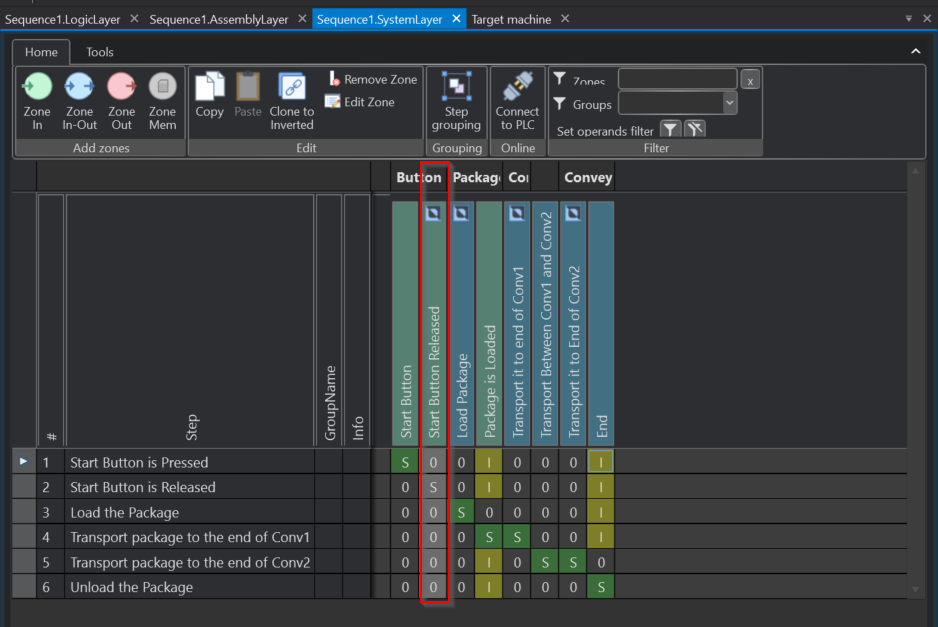
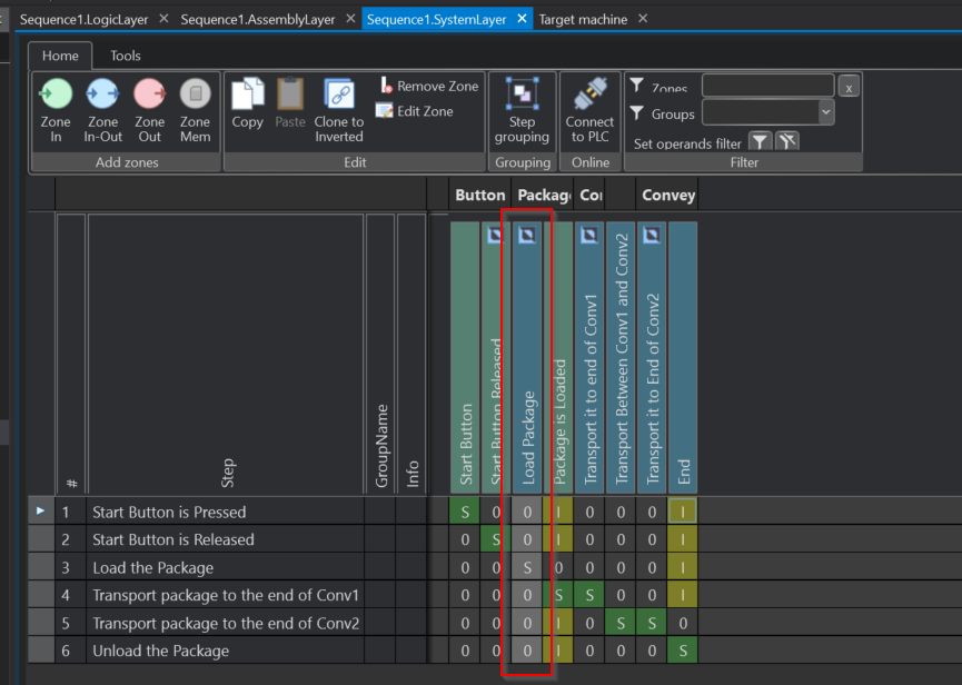
In the previous Tutorial, HardwareZone defined the following Zones as shown in the diagram below. Each zone can also be used to check and manipulate the status from Selmo’s HMI generation.
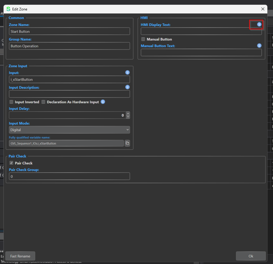
First click on Zone In on the Start Button.
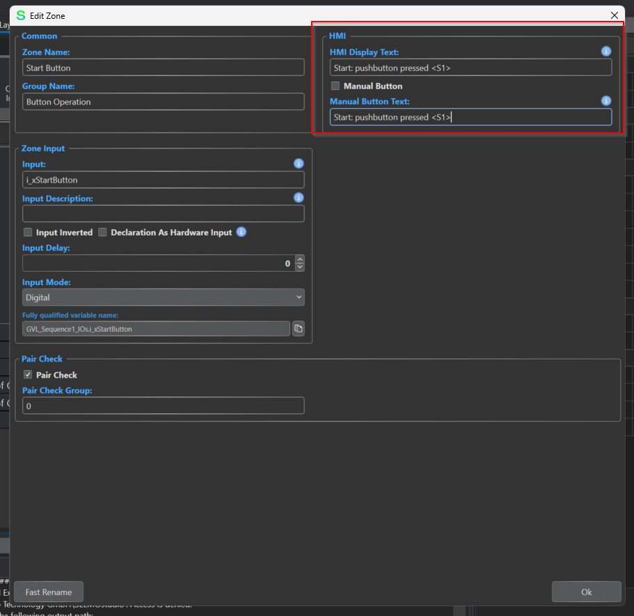
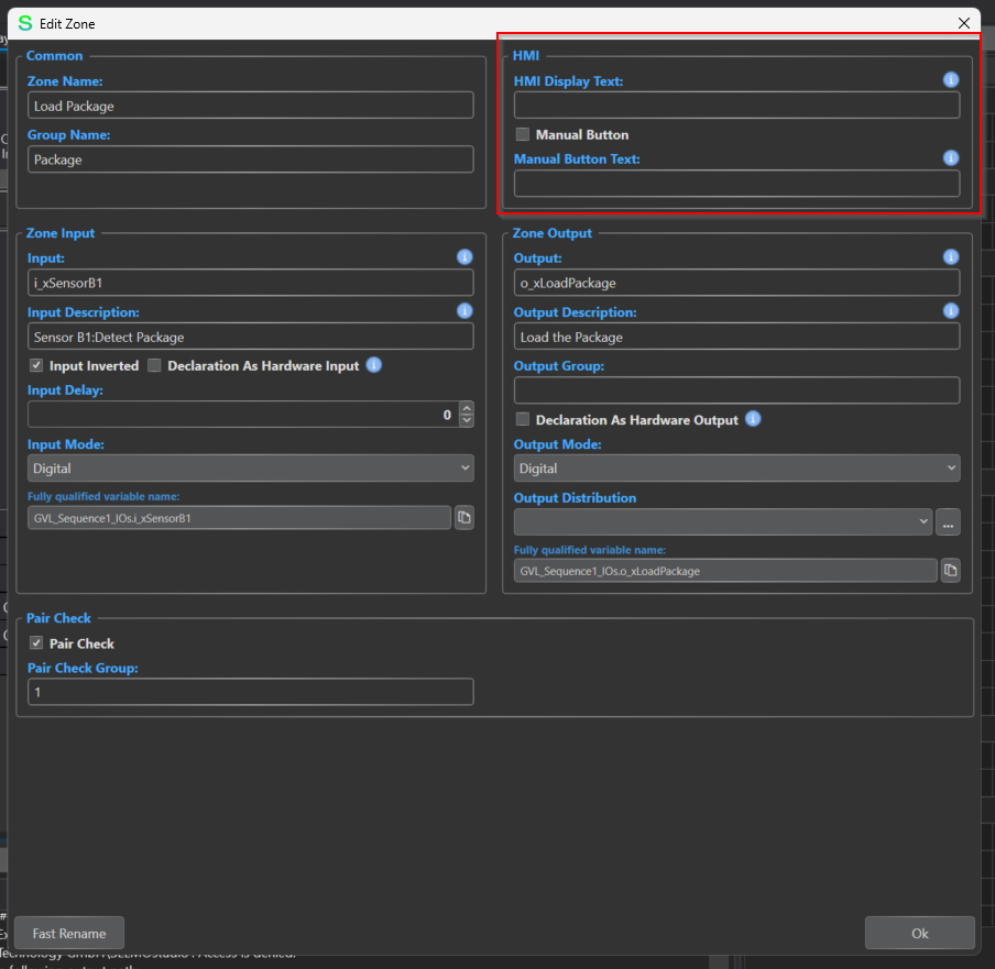
The Edit Zone settings screen has an HMI section, which contains HMI Display Text and Manaul Button Text Options.
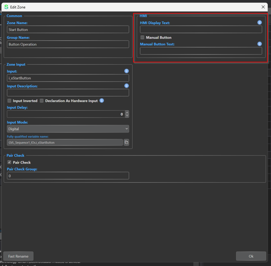
HMI Display Text
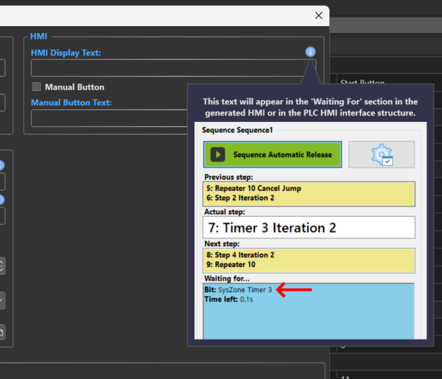
HMI Display Text displays the corresponding Zone In text on the Selmo HMI. In addition, clicking on the button with the red frame will display a detailed description of the relevant item.
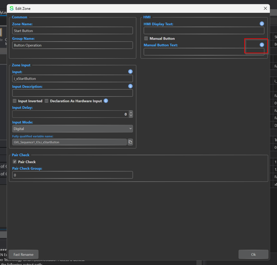
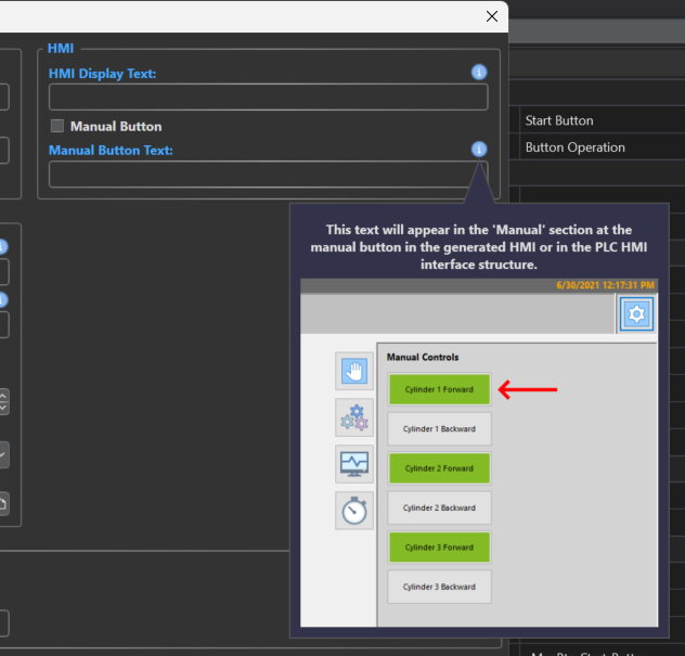
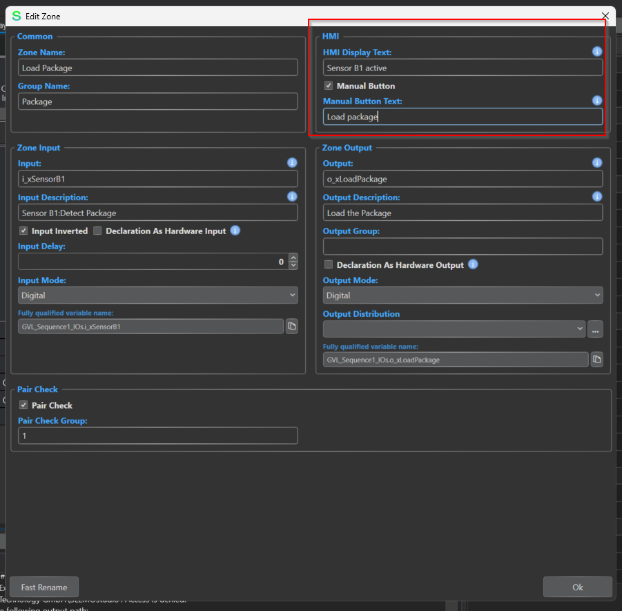
Manual Button Text
In this section, the corresponding zone is the display text of the button for Manual operation.
This time it was Zone-In that was set up, but both Display Text and Manual Button Text were also set up in one way.
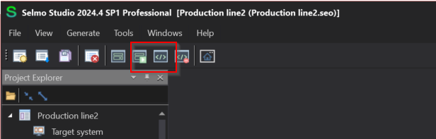
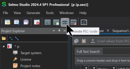
Generate the PLC Code and Import it into the Codesys project.
Finally, generate the HMI automatically.
Result
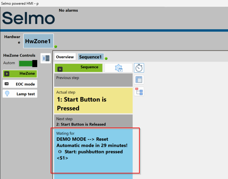
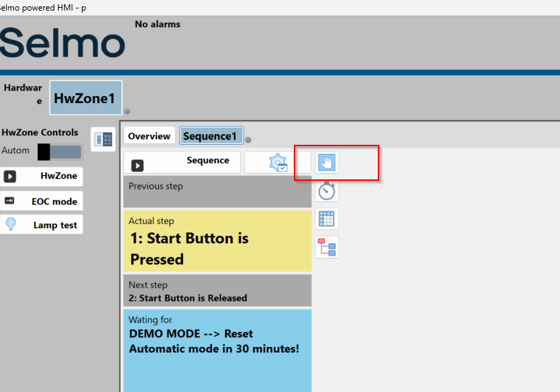
Done! You can see more items are displayed in the HMI.
Define other Zone-INs in the same way.
Configure Manual Button
The next step is to add manual operation buttons to Zone In-Out.
Set the HMI item using the same operation as before.
Now put in the Manual Button checkbox. This will create a control button in the zone corresponding to the HMI generated by Selmo Studio.
Result
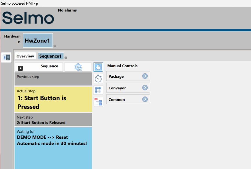
Done!The Selmo HMI has a hand icon for you to operate in manually.
The Load Package manual operation button is now displayed.
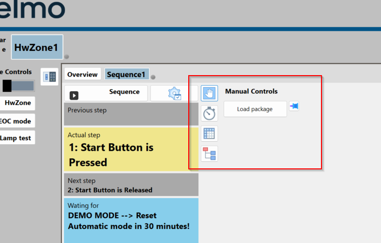
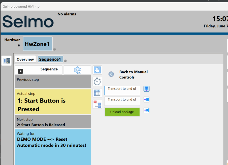
The operation is shown in the diagram below.
Finally, add an operating button to each Zone In-Out.
Parameters-Configure your Parameters
Next, the parameter functionality is introduced: with Selmo Studio, parameters can be used to display and manipulate the relevant parameters in the HMI.
You can also use the relevant parameters for your project.
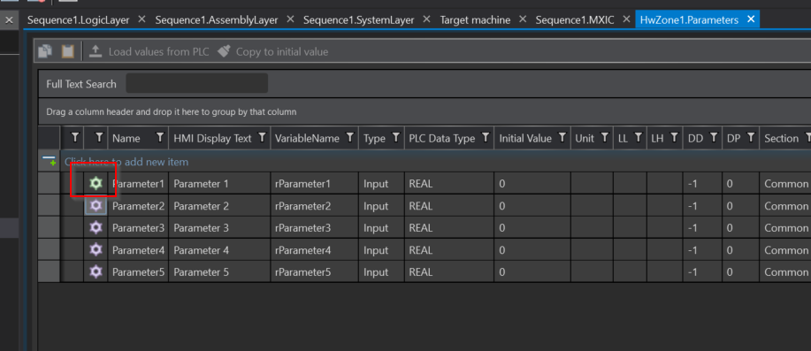
Click Plant>HwZone>Parameters and add the parameter.
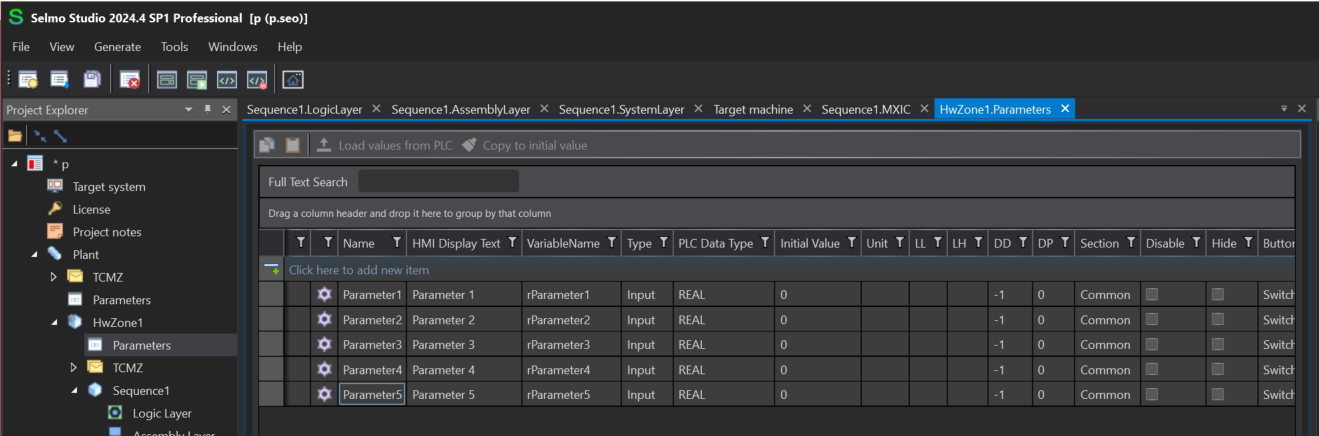
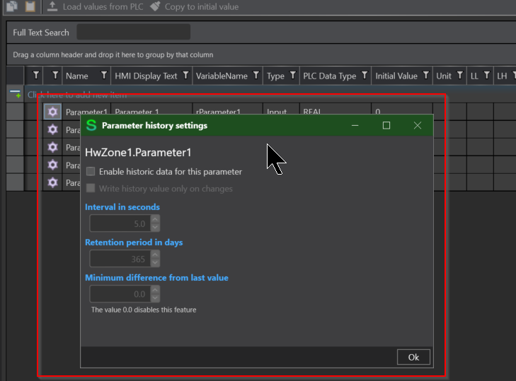
Detailed settings can also be made for each parameter, such as whether to enable the Historic function.
Generate PLC-Code
Note that if you add parameters, you must generate the PLC-Code once more and import it into the project.
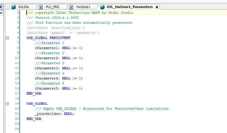
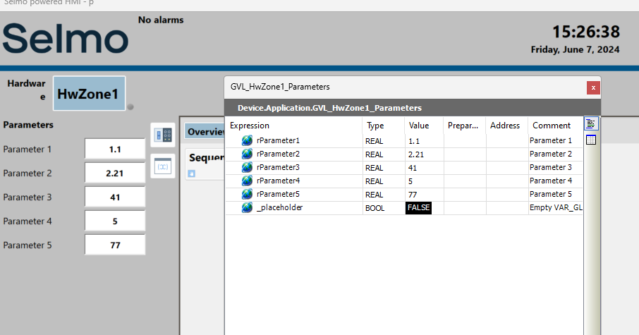
Done!GVL_HwZone1_Parameters has been added.

The same defined Parameters were generated in GVL_HwZone1_Parameters as before.
Result
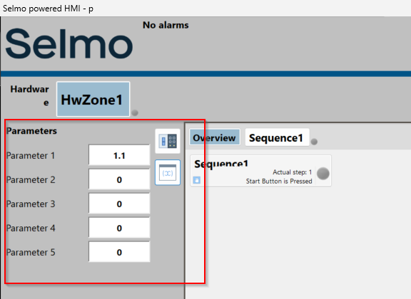
Once the Selmo HMI has been generated again, the buttons for the parameters have been created.
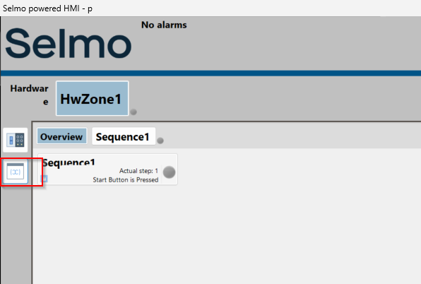
The variables you have just defined in Selmo Studio can also be displayed and entered.
In fact, the values entered in the Selmo HMI are reflected in GVL_HwZone1_Parameters.
Parameters-Enable Historic data
The next step is to activate the Historic function for the parameters. This function allows you to track changes in parameters.
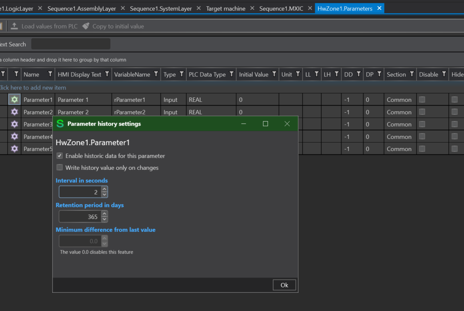
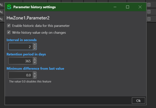
The colour of the gear next to the parameter item that has been changed from the Default setting becomes green.
You can also enable the Write History value only on changes checkbox, so that logging only occurs when parameters change.
Result
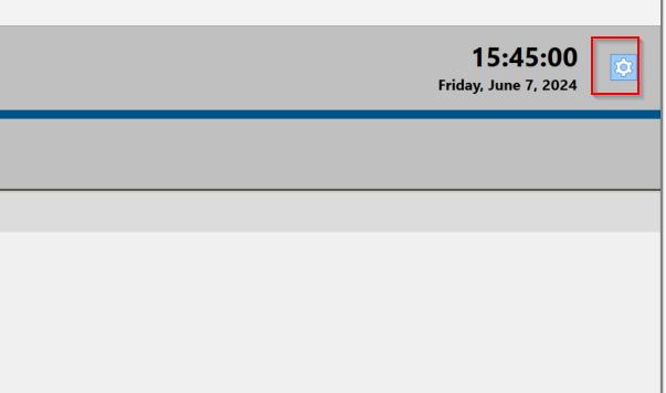
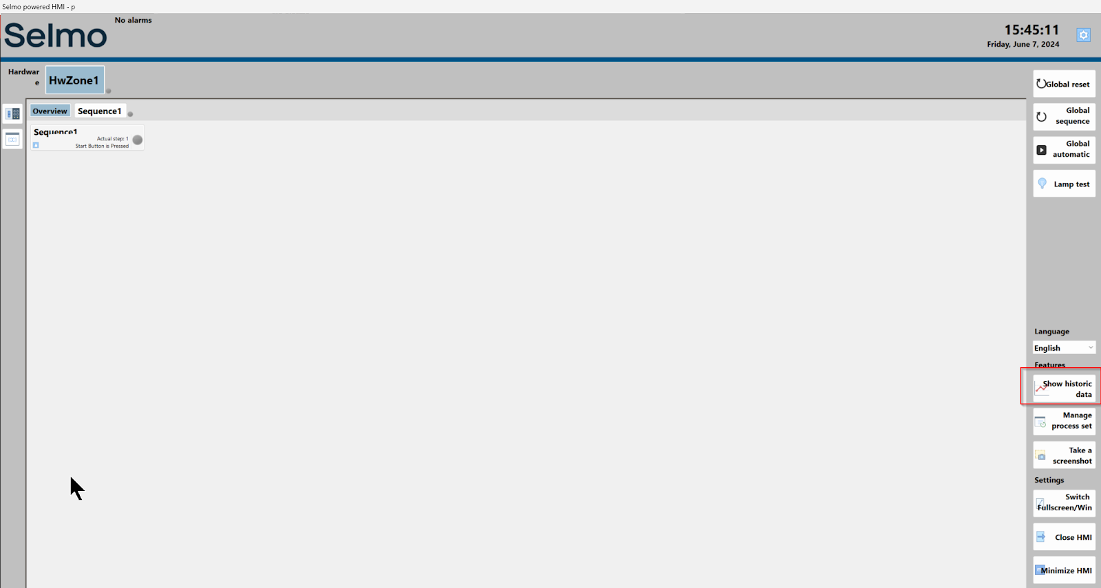
Click on the gear on the Selmo HMI.
Click Show Historic Data.
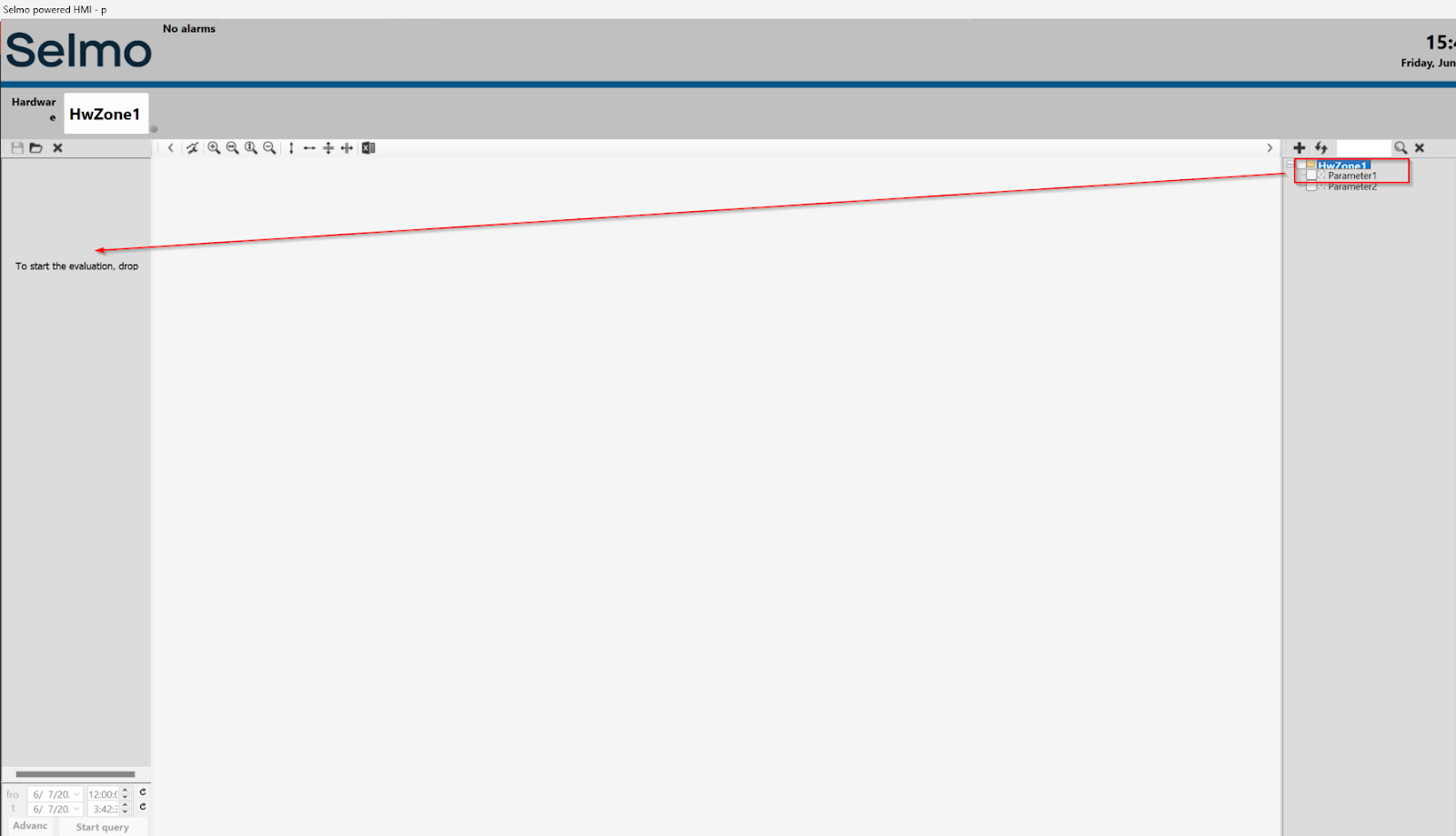
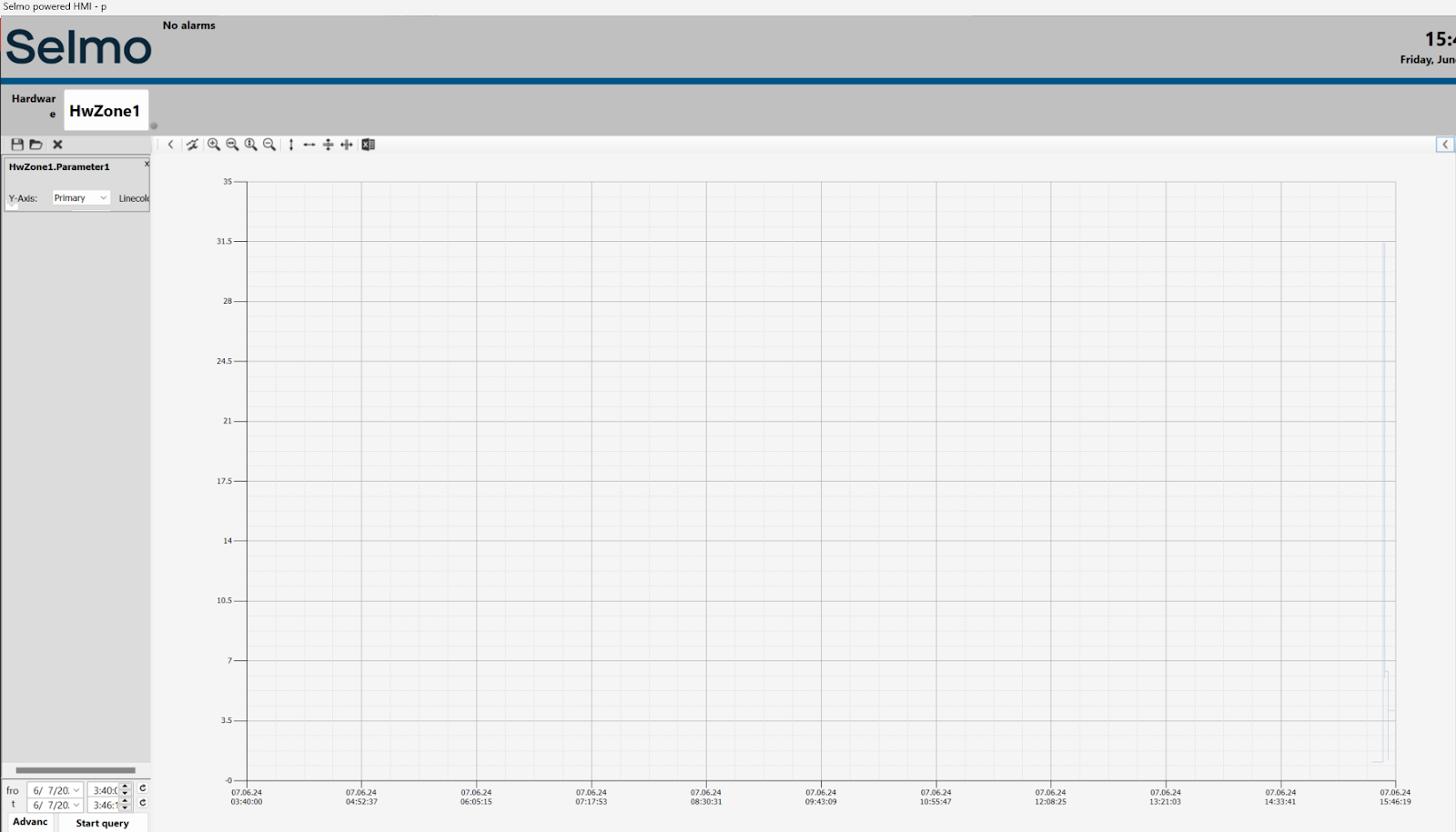
Historic data such as each parameter can be viewed from this screen.
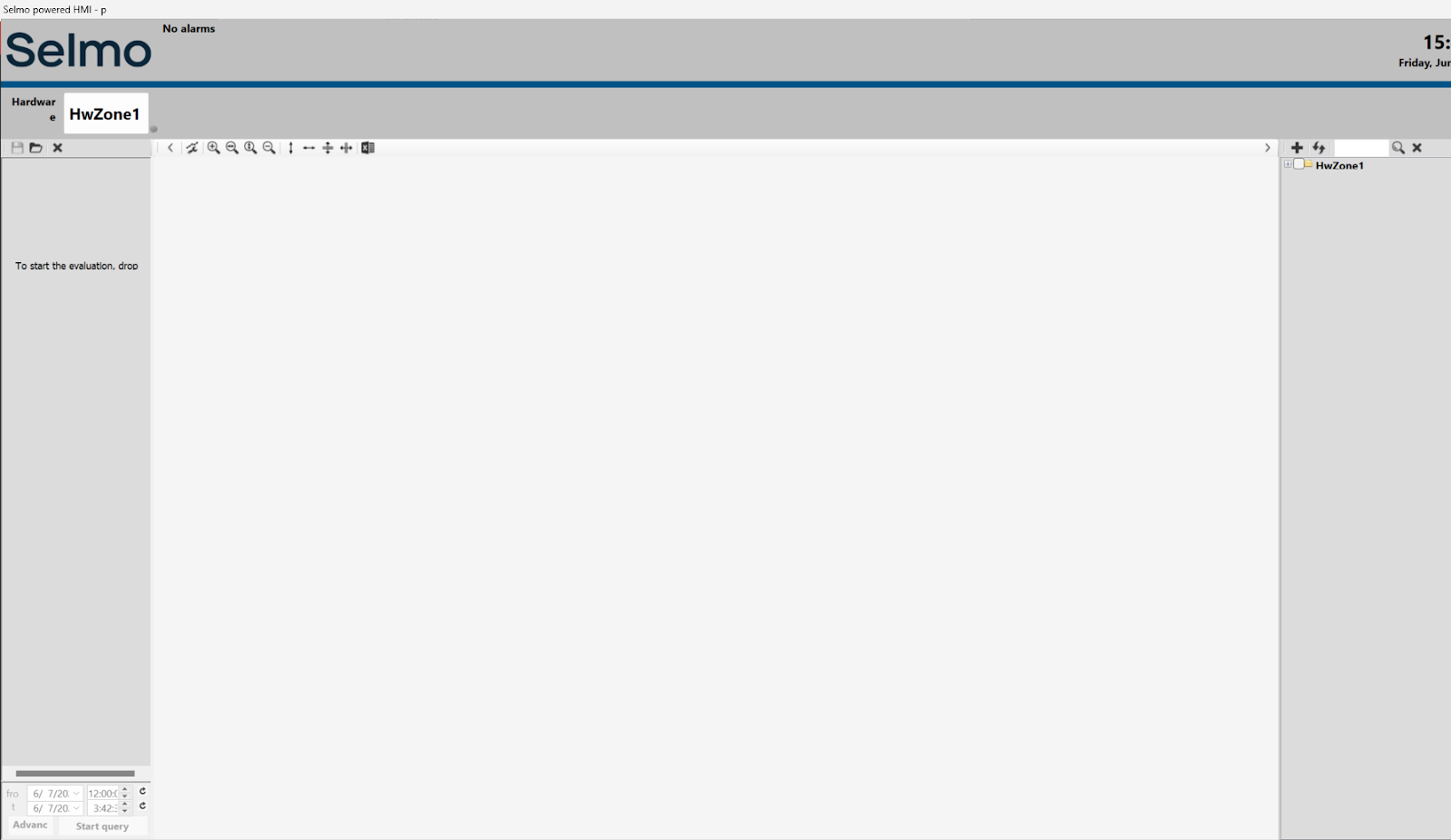
Add the Historic set variables to the Folder on the right to the Monitor area.
Finally, set the Historic data you want to check and use Start query to take the data.
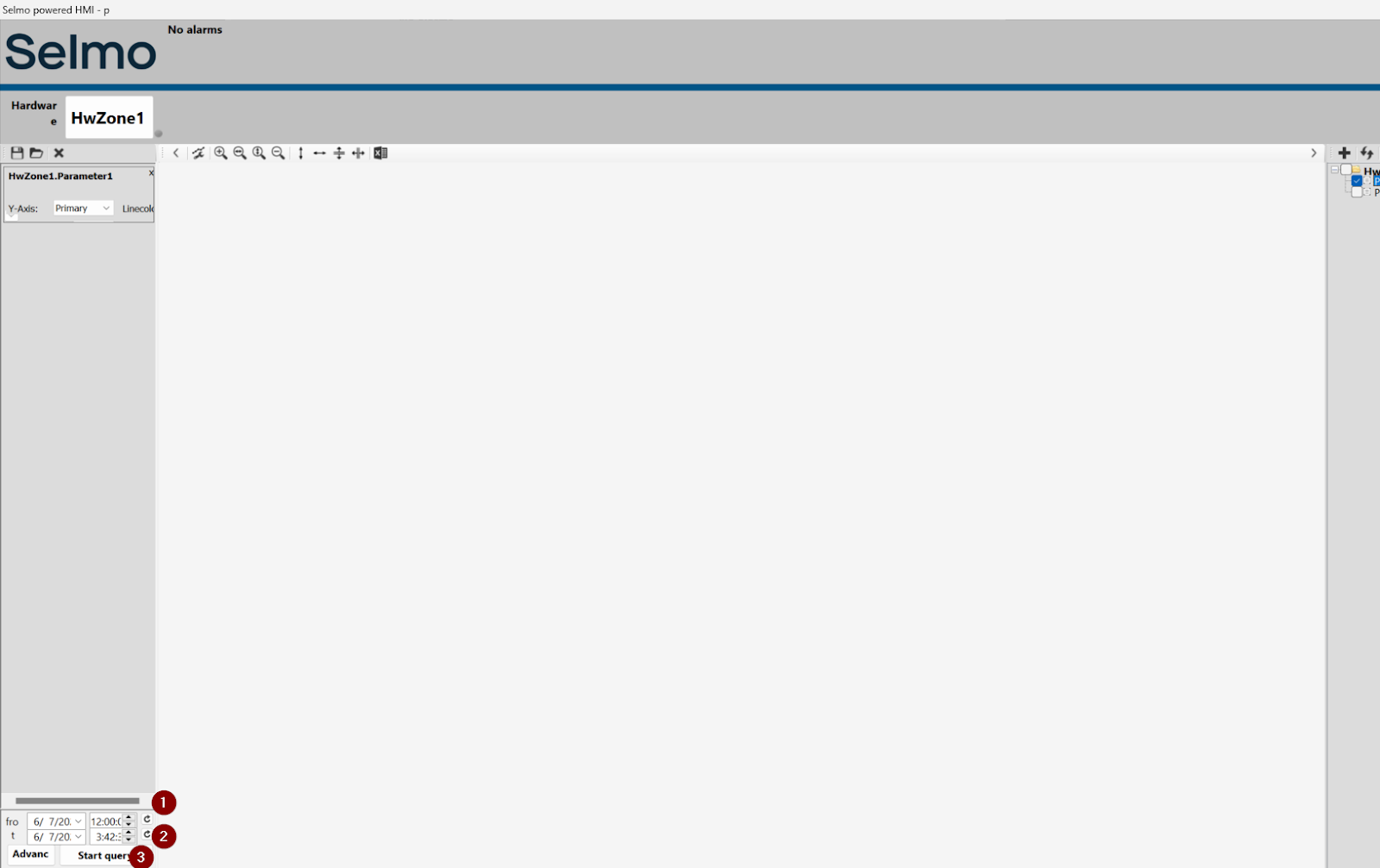
Done!
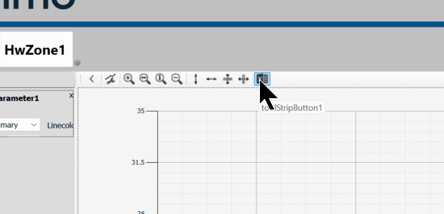
Export data
Historic data can also be exported by clicking on the toolStripButton.
Set the Format and Location to be exported.

Done!

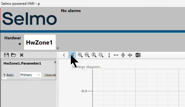
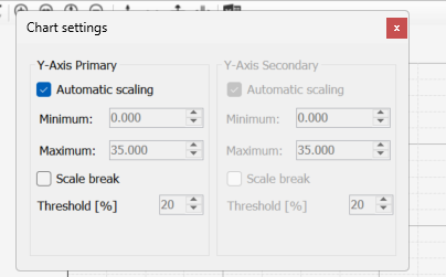
You can also click on the buttons in the Settings Diagram to change the X-Y axis scaling, for example.
Parameters-Configure Input Limit
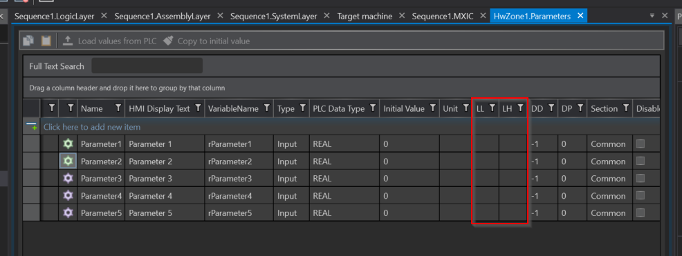
Now let’s set the upper and lower limits of the parameters. Put appropriate values in LL and LH for this.
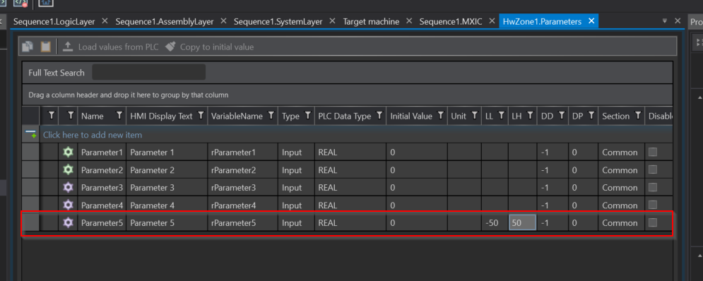
For example, set Parameter5 to LL=50 and HL=50.
Result
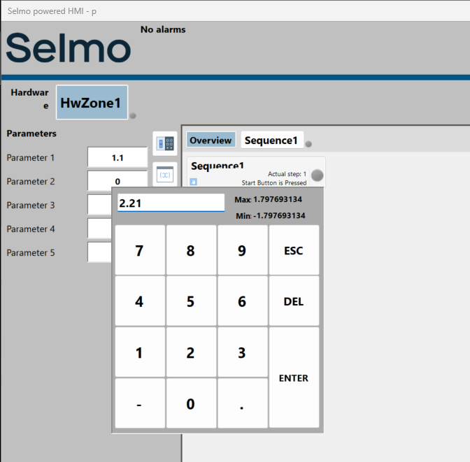
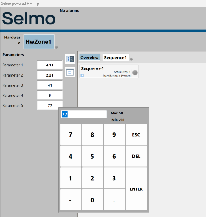
As shown in the diagram below, the HMI limits from -50 to 50.
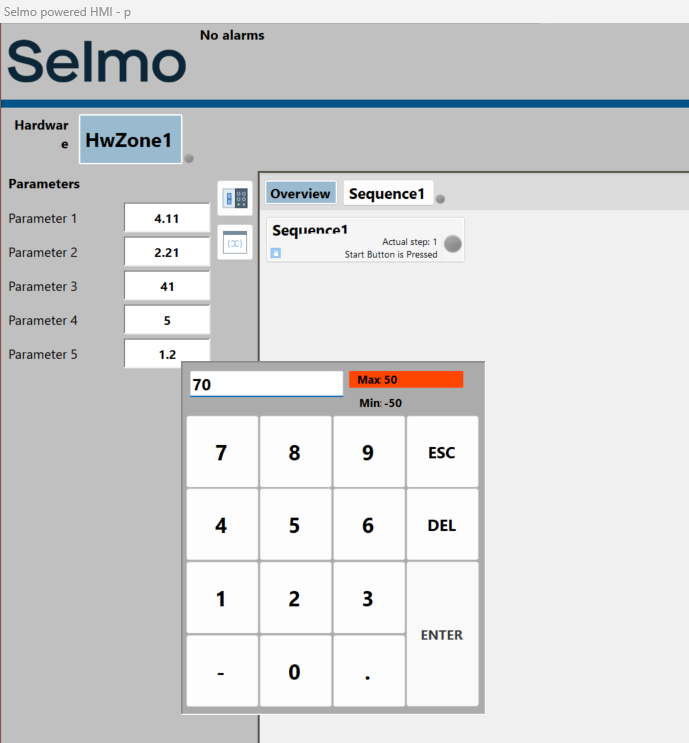
If the User’s input exceeds the Limit, the Max and Min areas turn red and the input cannot be changed.
Parameters-Group
The next step is Groups. If the project is huge, dividing the Groups makes it easier to manage the parameters. In this example, we divided the Section into Group1, Group2 and Group3.
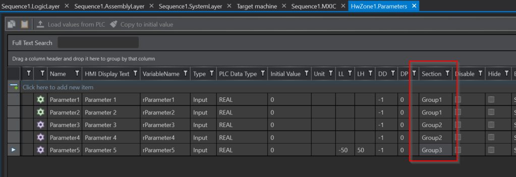
Result
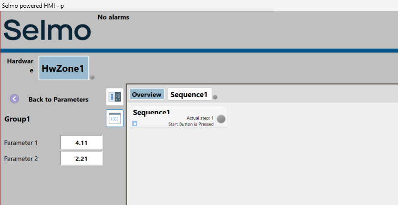
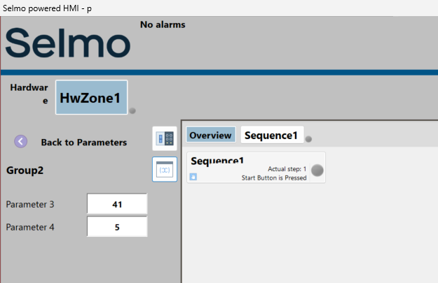
Done!The same parameter groups Group1, Group2 and Group3 were displayed in the HMI.
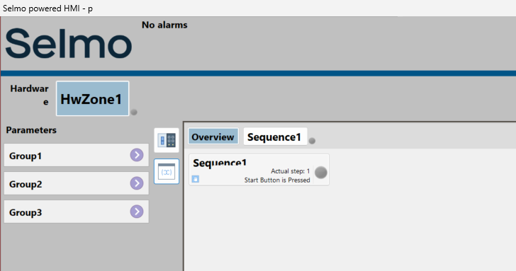
Each parameter was also divided into groups as set out in the Selmo Studio project.
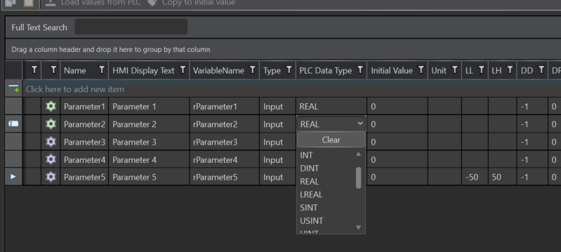
The data types of parameters are not only real numbers, but also DINT, INT and Bool.
Parameters-Disable
By inserting this Disable checkbox, the relevant parameter can be Interlocked as Input Disabled when it is in automatic mode.
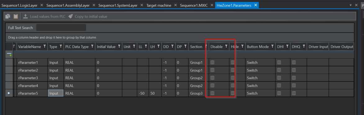
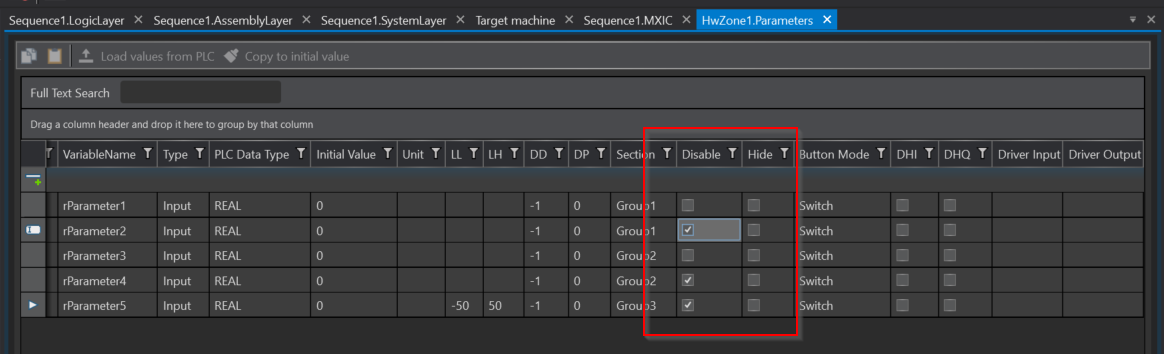
In this example, the Checkbox of Disable is put in several parameters.
Result
When HwZone1 is not in automatic mode, all parameters can of course also be changed.
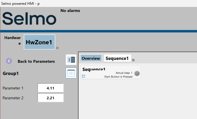
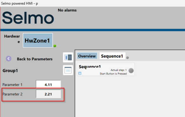
And once HwZone1 is changed to automatic mode, Parameter2 in Group1 can no longer be entered.
Parameters inside Sequences
Parameters can have their own parameters in each sequencer as well as in Global, which exists in the HwZone.
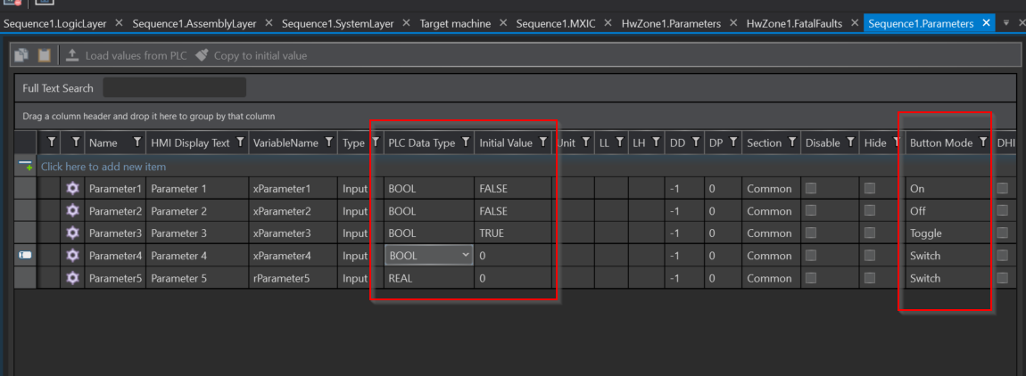
In the example below, five BOOLEAN type parameters are defined and various Button Modes are set.
Result
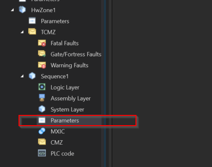
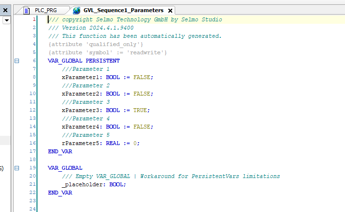
Done!This time, GVL_Sequence1_Parameters was generated in HWZone1>Sequence1>.
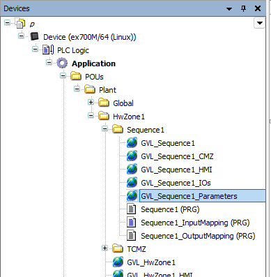
The BOOL variable defined earlier was created inside.
A button for the parameter has been added within each sequence.
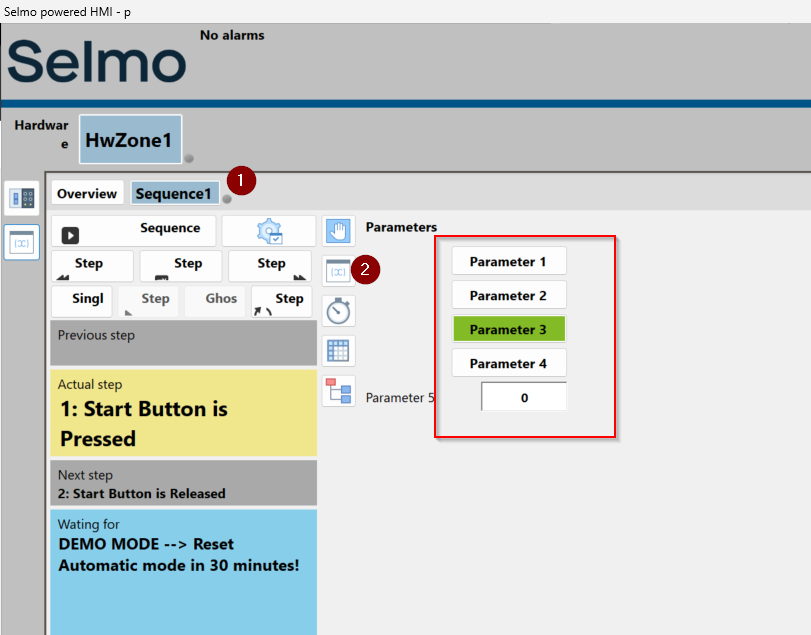
The operation of each button is as follows.