In this tutorial I will show you how to configure an Ethernet ip adapter using the ROBOGUIDE software from Fanuc,and implement a real time Io exchange to a raspberry with codesys runtime.
Hope you like this.
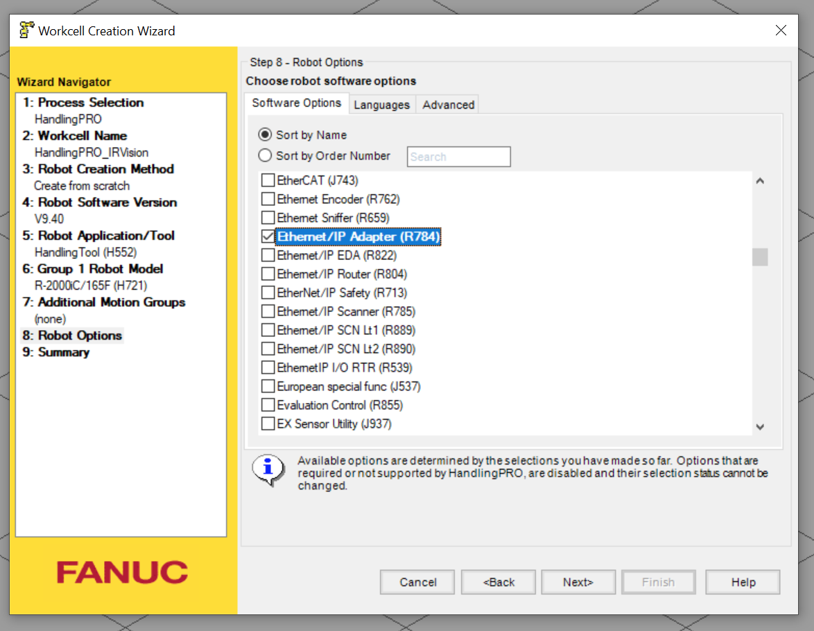
Options
Add the R784 options before you create the cell.
FANUC のIN/OUT
Analog(AI/AO)
The Analog input/output.
Digital(DI/DO)
The binary input/output.
Robot I/O(RI/RO)
The data exchange between controller and robot. These signal amounts are dependent on the robot axis.
Group I/O(GI/GO)
A group to combine servels of DI/DO into one integer.
UOP(UI/UO)
The memory area for plc data exchange.
Robot Controller Reset
We need to reset the robot controller while configuring ,here is one way to reset it.
Go to Robot >Restart Controller >Cold Start to reset it.

EDS Export
Open MENU>FILE>File.

Click the backup button.

Choose Com.Conf.

You can see the “Save Successful ” message after the eds file is exported.

Access the directory of your project,
The directory is Documents> yourprojectname >Robot_1>UD1.
You can find the eds files of the robot.

Host Comm SETUP
Go to SETUP>SETUP2 and open the 8 Host Comm menu.

Choos 1 TCP/IP.

configure the IP address and subnet in port#1.

Ethernet/IP Setup
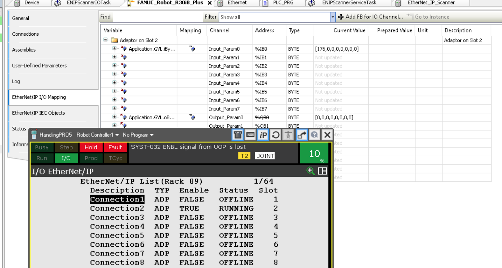
open the I/O>EtherNET/IP.

You can set couples connections but only connection 1 is used in this tutorial.
ADP is the meaning of the Adapter.
Please turn the enable setting from false to true one time to activate the adapter connection.

Adapter configuration

STATUS
OFFLINE
Connection is invalid.
ONLINE
connection is enabled but not activated.
RUNNING
connection is enabled and Io data is exchanged.
<RUNNING>
Connection is enabled , Io data is exchanged and auto reconnect is used.
PENDING
configuration is changed anda reset operation is requested by the Robot controller.
Slot
It is used to map your DI/DO signals.
COMFIG
Click the CONFIG button in the connection screen.
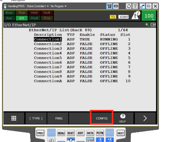
The input and output size are 4 words.
Please match this setting in the scanner side,
And also the IP address of the controller.

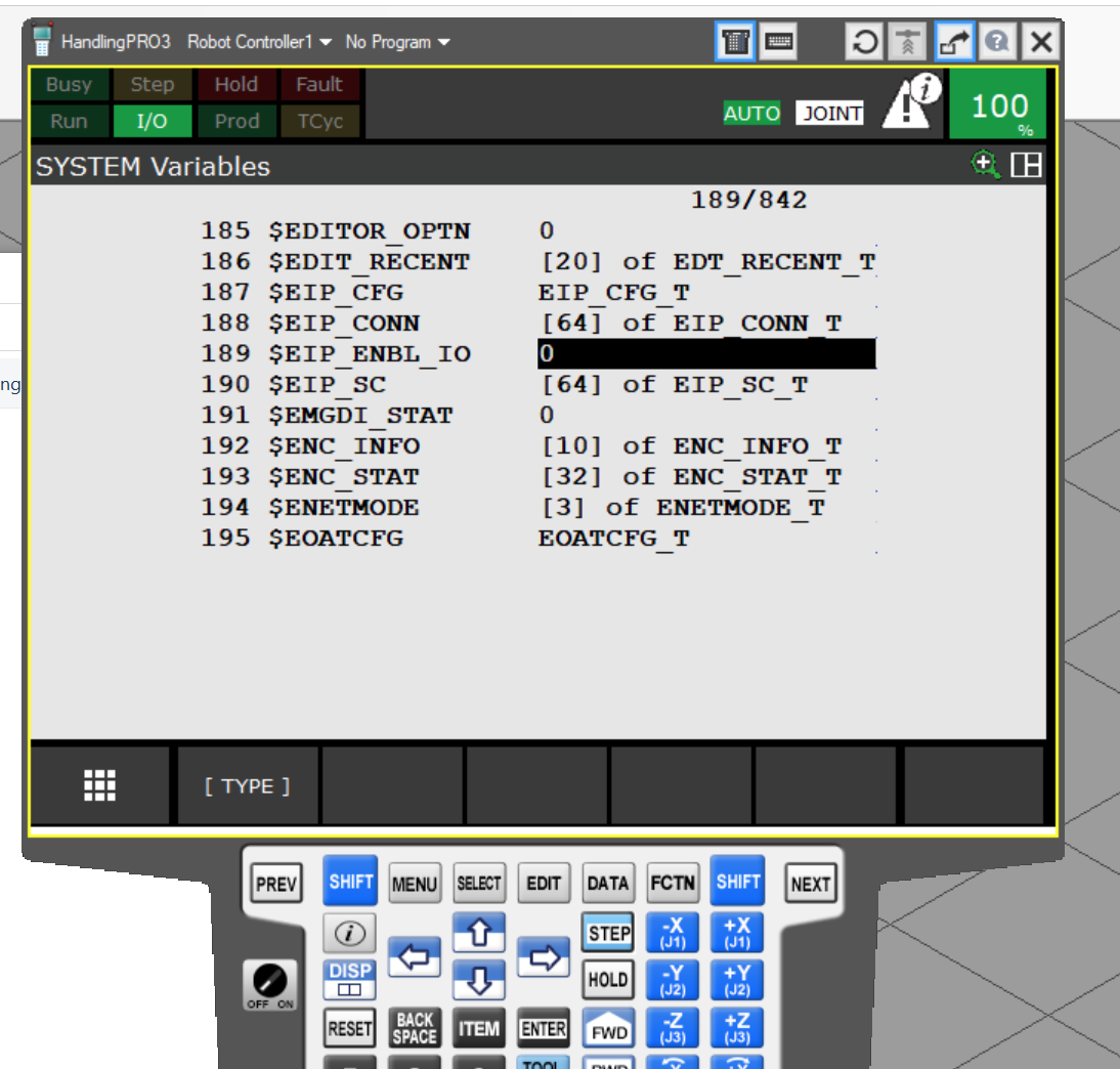
Variables189 EIP_ENBL_IO
Go to 6 SYSTEM and open the 2 Variables menu.

Set the No.189$EIP_ENBL_IO to 1.
System Config
Remote/Local setup
Go to the System>Config and the No.42 parameter- Remote/Local setup to Remote.

Remote means the robot will be controlled by plc.
Local means the robot will be controlled by the robot controller itself.

Enable UI Signal
Go to System>Config and set the 7 Enable UI Signals to true.

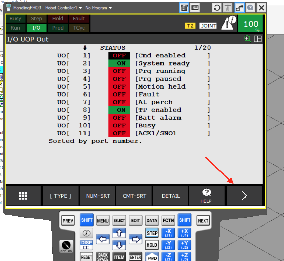
UOP setting
Finally we need to set the UOP.
Go to I/O>UOP.

You can change the status monitor screen by clicking the IN/OUT button.
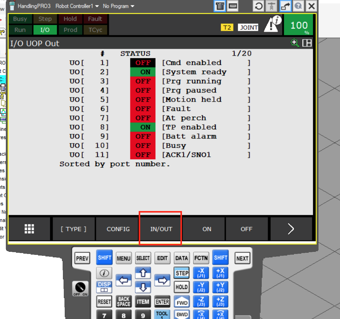
The configuration of input/output are the same,
I will show you how to configure the output side.
Click the CONFIG button.

Input 89 as the rack number and this is the magic number of Ethernet ip configuration.

Codesys Side
please refer to this link to setup an Ethernet ip scanner in codesys.
You can also try the beckhoff Ethernet/IP Scanner.
Install the eds file that exported from ROBOGUIDE software.

Go to the scanner and use the scan for devices function.
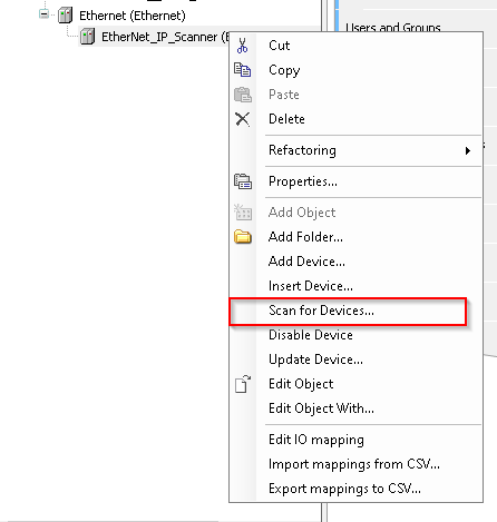
The robot controller is found in the network and click the copy to project to insert it into your codesys project.

The robot is inserted.

In the connection tab, slot 1 is used in default.
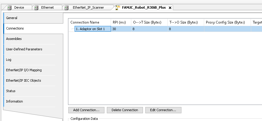
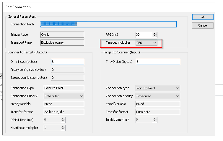
if timeout
click the edit connection button.

Adjust the timeout multiplier or try to use another slot.
This is the status shown in ROBOGUIDE.

And also you can view the current signals on the codesys side also.