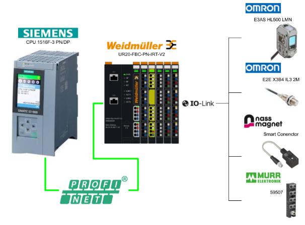
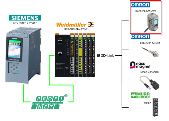
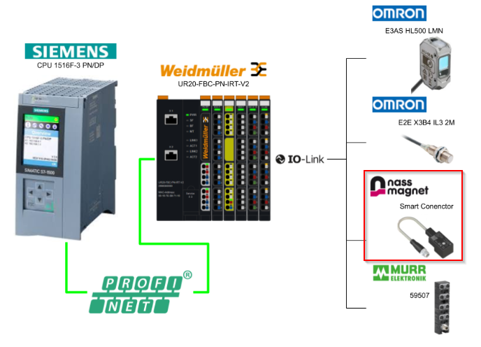
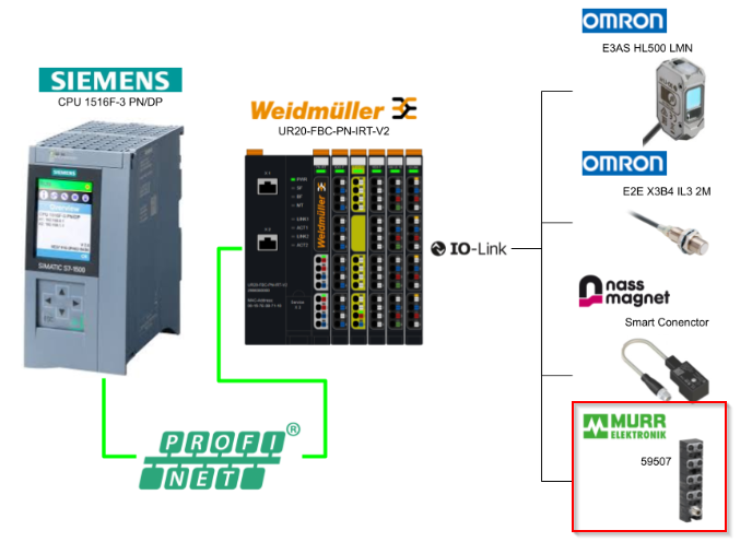
This article shows how to build a Profinet network with a Siemens CPU 1516F-3 PN/DP in combination with Weidmuller’s Profinet Coupler UR20-FBC-PN-IRT-V2 and UR20-4COM-IO-LINK with four channels, start from zero.
The IO-Link devices used in this article are also from Omron Nass Magnet and Murrelektronik.
Let’s enjoy FA!
Reference Link
http://soup01.com/en/category/weidmuller/
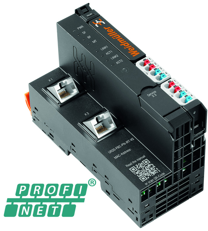
UR20-FBC-PN-IRT-V2?
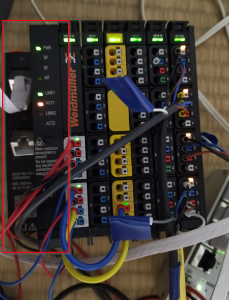
The UR20-FBC-PN-IRT or UR20-FBC-PN-IRT-V2 fieldbus coupler is a PROFINET I/O device certified by the PROFINET user organization.
The coupler is the head module of the u-remote system bus and can connect up to 64 active u-remote modules.
Its PROFINET coupler has two Ethernet ports and the integrated switch supports line network structures.
It can also be accessed by a system-independent web server application via USB service interface or Ethernet. All information such as diagnostics, status values and parameters can therefore be read and all connected modules can be simulated or forced to operate.
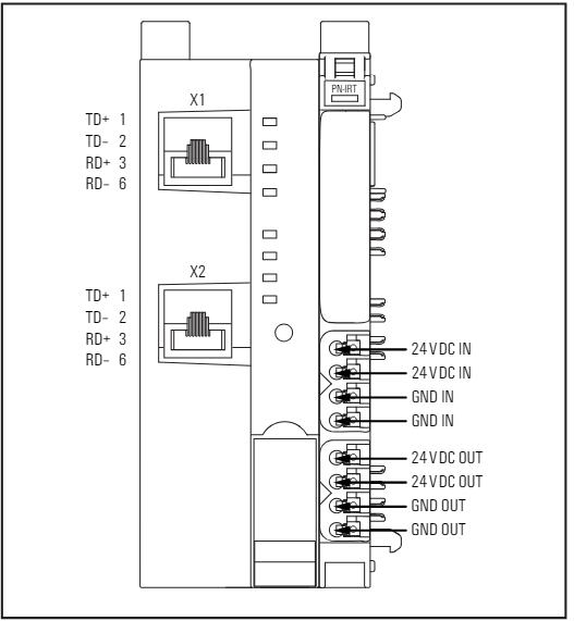
Wiring
This is the wiring diagram for the UR20-FBC-PN-IRT-V2.
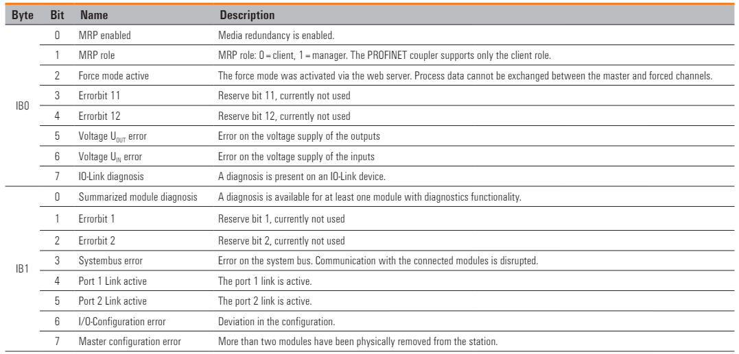
Process Input Data
This is Process Input Mapping for UR20-FBC-PN-IRT-V2.
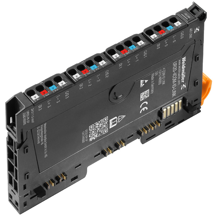
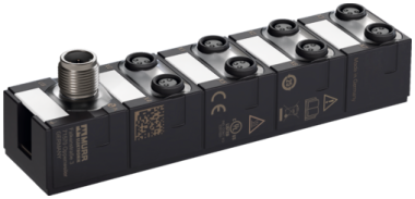
UR20-4COM-IO-LINK?
The digital communication module UR20-4COM-IO-LINK is an IO-Link master according to the IO-Link specification V1.1.2 and allows one IO-Link device to be connected to each plug-in connector. The IO-Link device can also be port class A or, with the use of an additional potential distribution module, also port class B.
In addition, one digital input is available on each plug-in connector and process data is exchanged with the connected IO-Link device via the respective IO-Link port. So the four communication channels can also be used as digital inputs or digital outputs for standard field devices.
Apart from that, acyclic data (diagnostic data, parameter data, status information) can also be exchanged. Thereby, the parameter data of the connected IO-Link devices can be stored in the master module, which is managed from the parameterising server (data storage).
Weidmüller provides the u-mation configurator software, which can also be used to configure the IO-Link system of the UR20-4COM-IO-LINK.
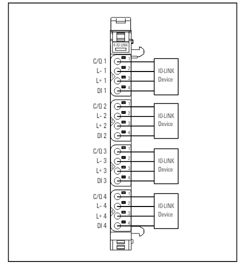
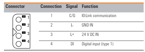
Wiring
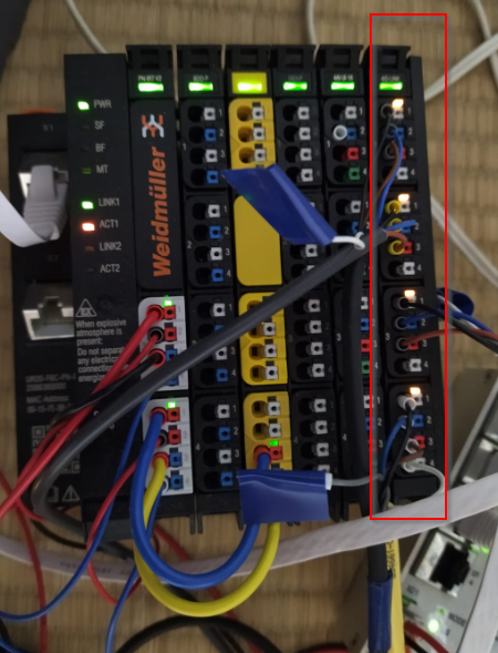
This is the wiring for the UR20-4COM-IO-LINK module.
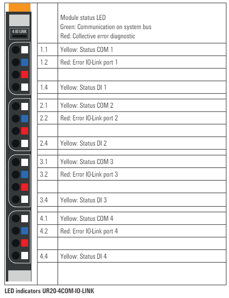
Module LED
This is the LED display of the UR20-4COM-IO-LINK module.
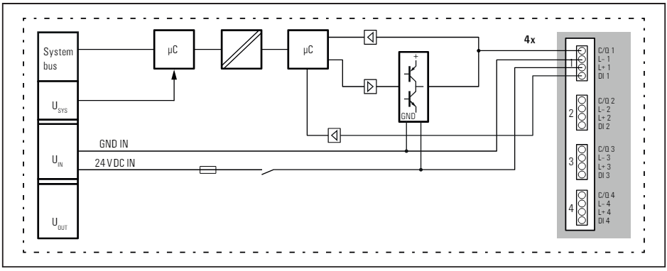
Block Digram
This is a block diagram of the UR20-4COM-IO-LINK module.
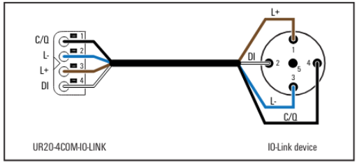
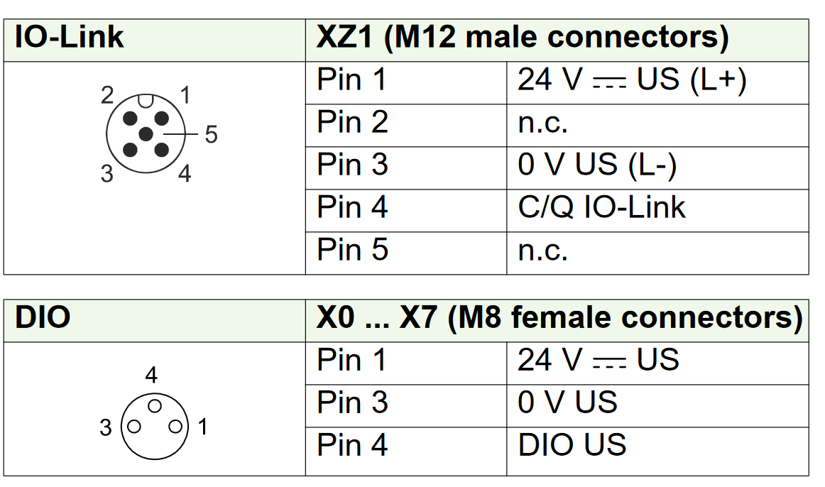
Wiring for class A port
This is the wiring diagram for the UR20-4COM-IO-LINK module as Class A Port.
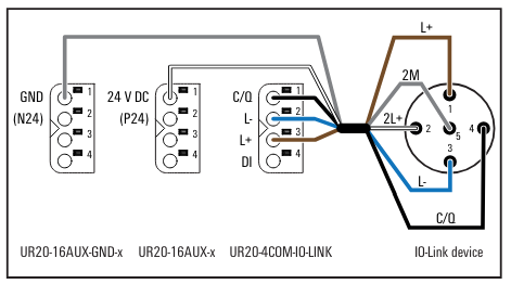
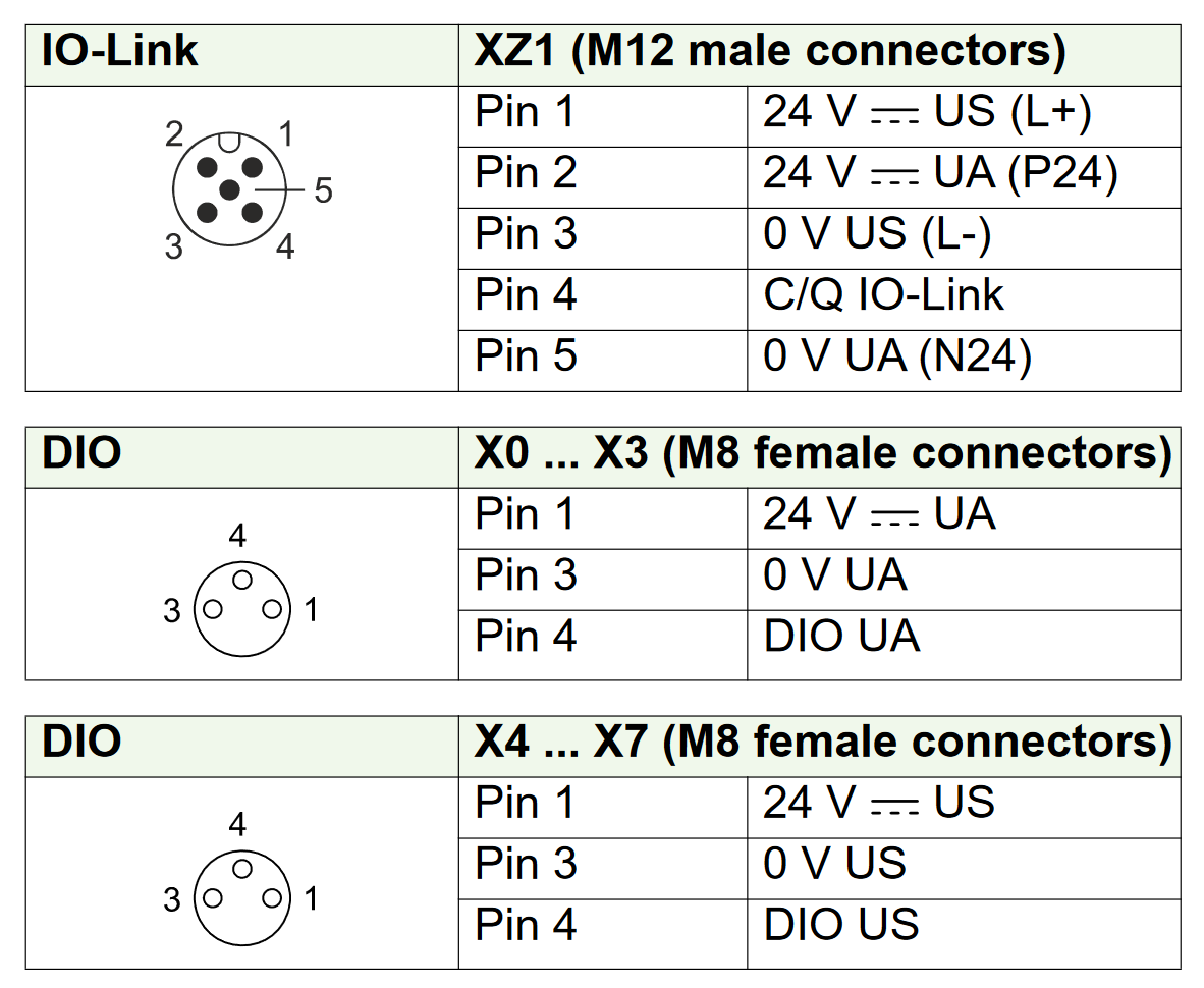
Wiring for class B port
This is the wiring diagram for the UR20-4COM-IO-LINK module as Class B Port.
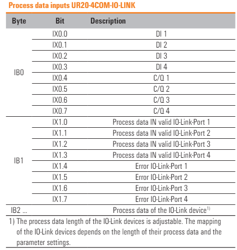
Process data Input
This is the input data for the UR20-4COM-IO-LINK module.
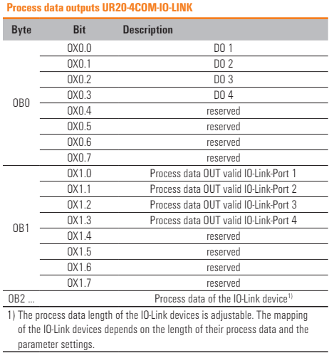
Process data Output
This is the output data of the UR20-4COM-IO-LINK module.
MVP8-P3 DIO8 8xM8-3 IOLA12 E0 59607
This is the MVP8-P3 DIO8 8xM8-3 IOLA12 E0 59607 from murrelektronik used in this article. This module has the following features.
- IO-Link hub with 30 mm plastic housing
- 1 x M12 IO-Link class A
- 8 x M8 I/O
- 8 configurable digital inputs/outputs
This is Layout 59607.
PortA
This is the wiring diagram for the 59607 as PortA.
PortB
This is the wiring diagram for the 59607 as PortB.
Port Base Input Data Bitmap
This is the Mapping of the input data when 59607 is used as Port Base.
Port Base Output Data Bitmap
This is the Mapping of the output data when 59607 is used as Port Base.
Pin Base Input Data Bitmap
This is the Mapping of the input data when using 59607 as a Pin Base.
Pin Base Output Data Bitmap
This is the Mapping of the output data when using 59607 as a Pin Base.
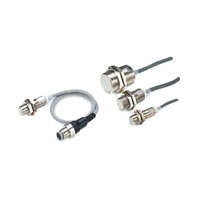
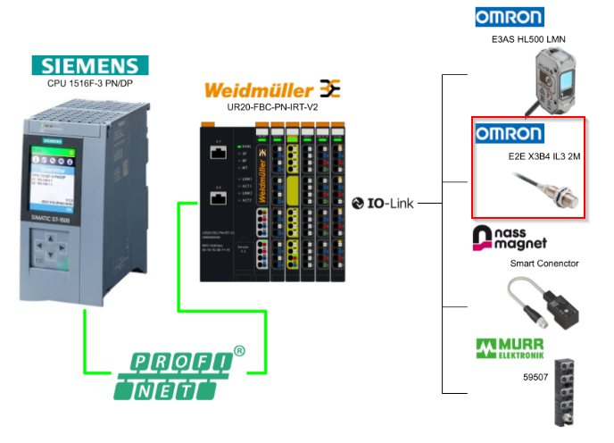
E2E_X3B4_IL3_2M
This is the OMRON E2E-X3B4-IL3-2M used in this article.
https://www.fa.omron.co.jp/products/family/3543/feature.html
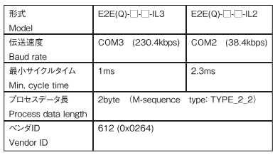
Specification
This is the IOLINK version of the E2E-X3B4-IL3-2M.
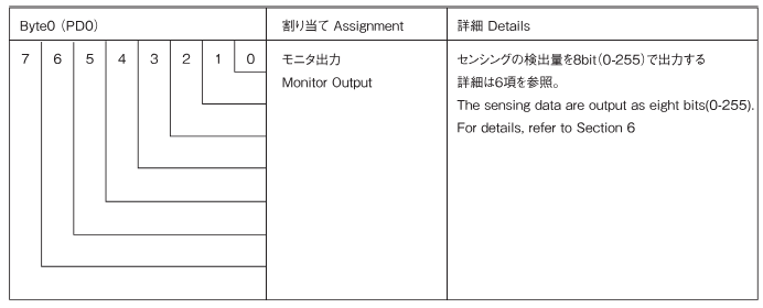
Process Input Data
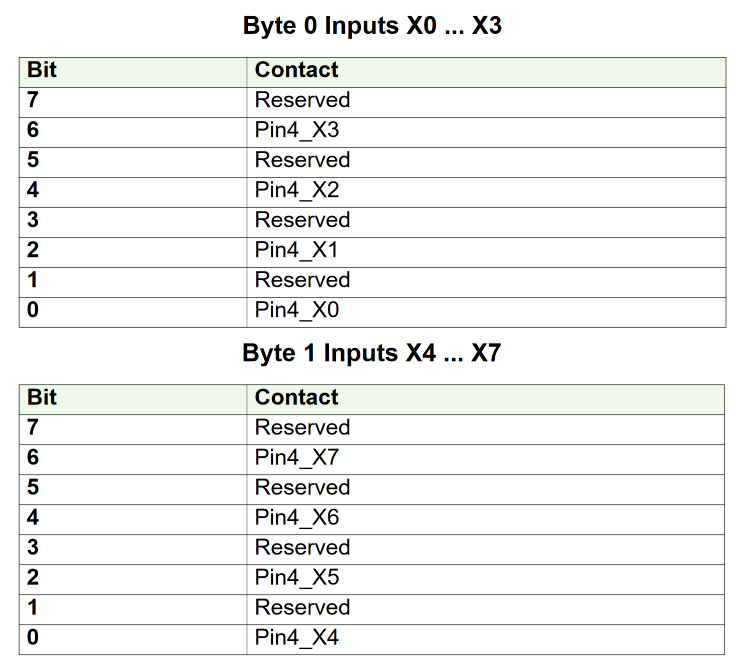
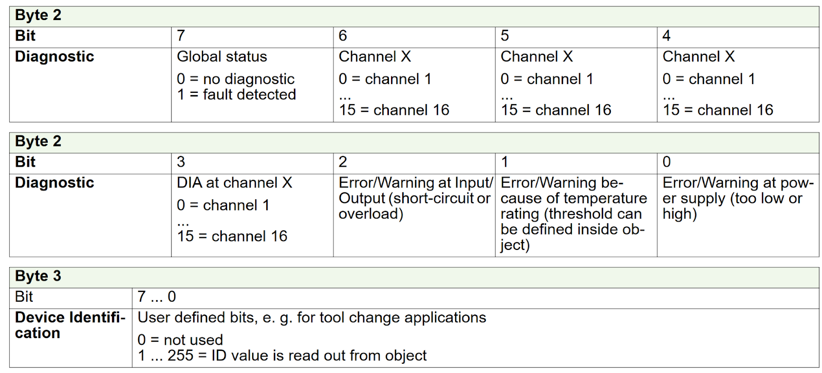
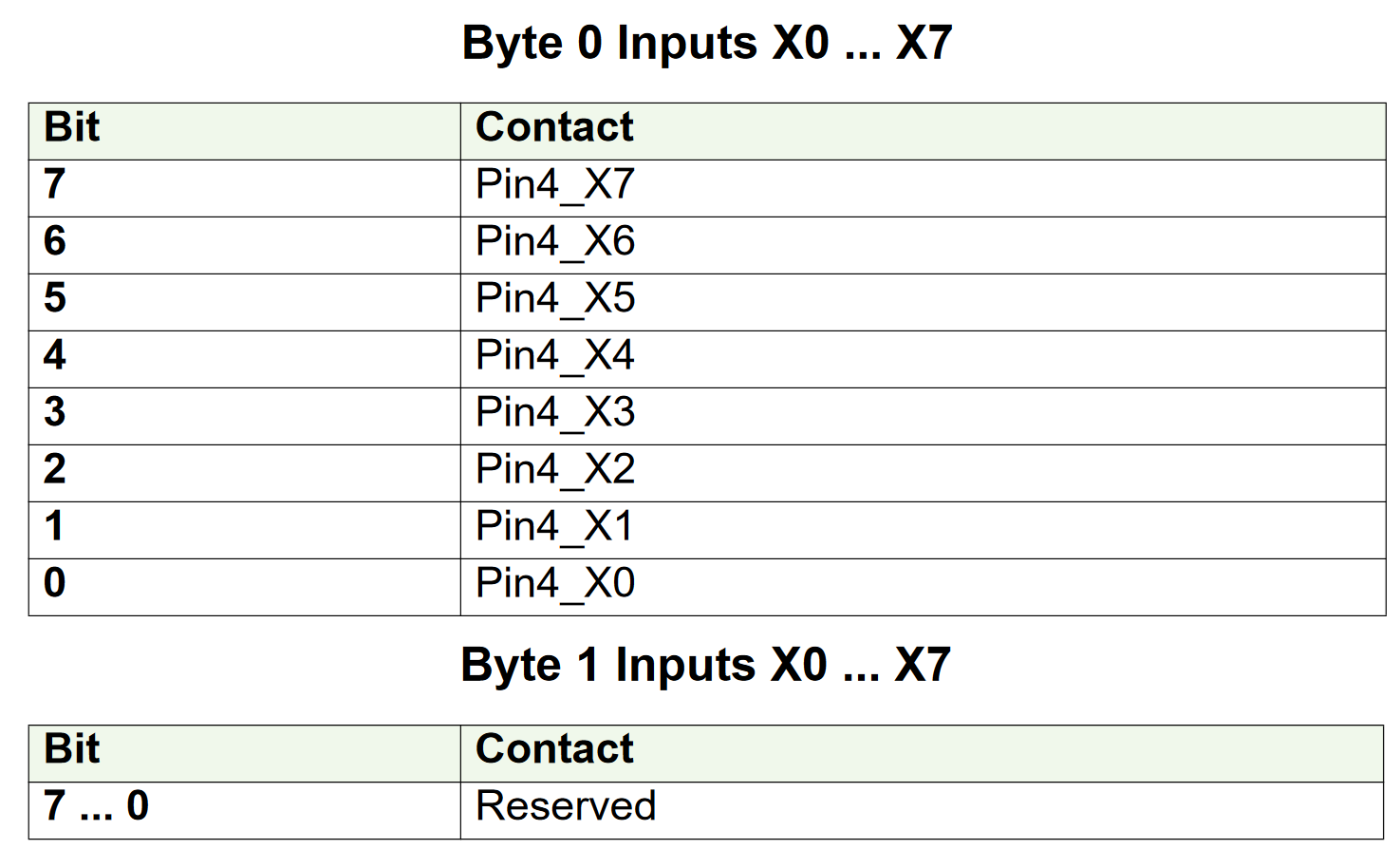
This is the Byte 0 input data Mapping of the OMRON E2E-X3B4-IL3-2M.
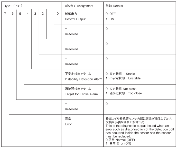
This is the Byte 1 Input Data Mapping of the OMRON E2E-X3B4-IL3-2M.
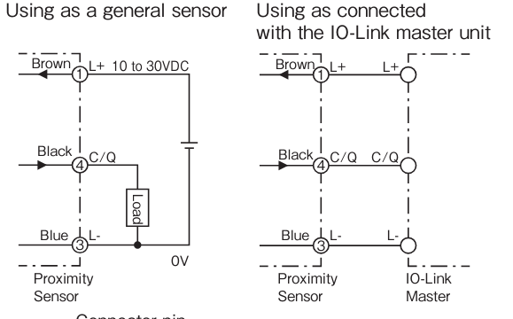
Wiring
This is a wiring diagram for an OMRON E2E-X3B4-IL3-2M.
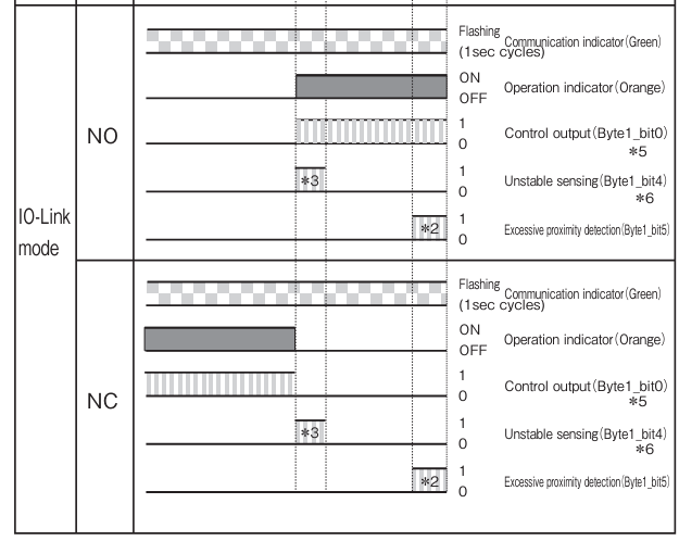
Flow
This is the IOLINK operating diagram for the OMRON E2E-X3B4-IL3-2M.
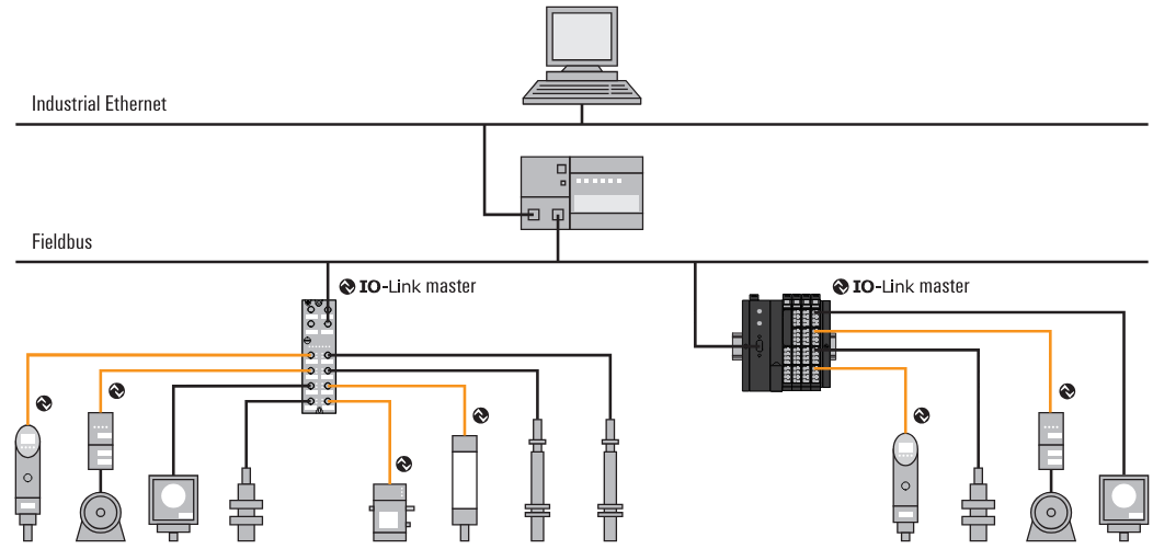
IO-Link?
IO-Link, a communication protocol for automation technology, is a technology that enables serial bi-directional point-to-point communication between devices at the sensor/actuator level or at the field or control level.
IO-Link enables acyclic exchange of parameters, diagnostics and identification data as well as cyclic process data, and IO-Link has been standardized worldwide in IEC 61131-9 as “single-drop communication interface for IO-Link has been standardized worldwide as “single-drop communication interface for small sensors and actuators” (SDCI) in IEC 61131-9.
The IO-Link system consists of two components:
- IO-Link master: represents the interface between the IOLink device and the host communication system.
- IO-Link device: field device capable of communication.
The IO-Link master and IO-Link devices communicate via the switch and communication cable C/Q, the IO-Link devices are supplied with voltage by the IO-Link master via the L+ and L- cables. Depending on the port class, additional connections can also be made to the IO-Link ports.
Port class A? Port class B?
IOLINK has Port Class A and Port Class B.
- Port Class A: The function of the additional connection is selected by the manufacturer. Often this connection is used with additional digital inputs or outputs.
- Port Class B: The IO-Link master provides a second supply voltage via two further connections. c
Connect the IO-Link device to the IO-Link port of the IO-Link master with 3 or 5 cables.
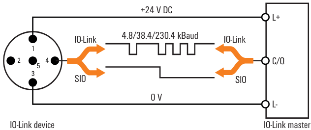
IO-Link ports can operate in IO-Link mode for bi-directional communication or in SIO mode as digital inputs or digital outputs.
In IO-Link mode, the IO-Link master automatically sets the transmission rate suitable for IO-Link communication after start-up and the IO-Link master checks the identification of IO-Link devices.
The data storage function also allows correct parameterisation of IO-Link devices without additional programming, even after the IO-Link device or IO-Link master has been replaced.
In addition, IO-Link devices can be parameterised using Configuration Software or asynchronous communication services. For this, device description files (IODDs) from the IO-Link device manufacturer are required; IODDs can be found and downloaded using the IODDfinder on the IO-Link Consortium website.
https://io-link.com/en/IODDfinder/IODDfinder.php
Implementation
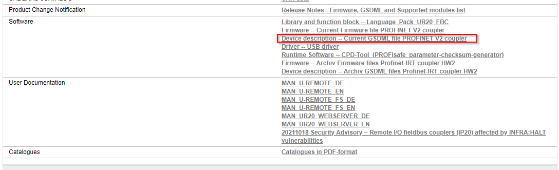
Download GSDML File
Download the GSDML File for UR20-FBC-PN-IRT-V2 at the Link below.
https://catalog.weidmueller.com/catalog/Start.do?localeId=en&ObjectID=2566380000
Siemens Side
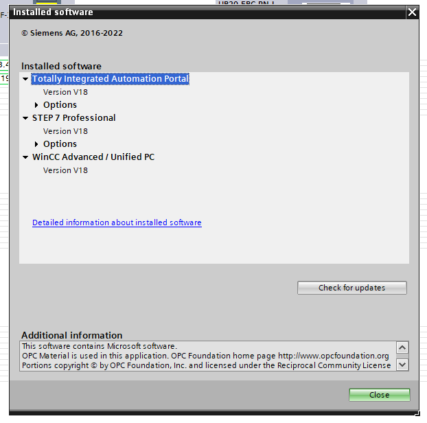
It is slightly older, but the one used in this article is TIAV18.
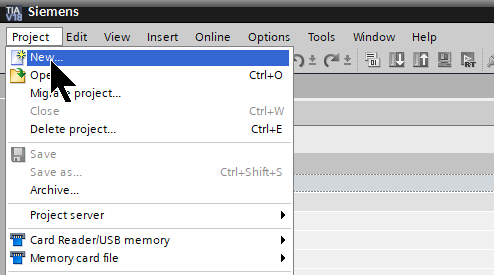
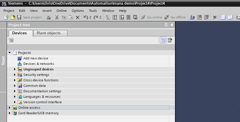
New Project
Create a new project at Project>New.
Enter the project name.
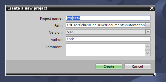
Done!
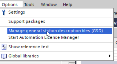
Install GSDML
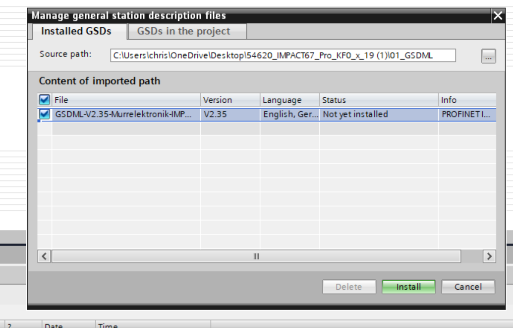
Click Options>Manage general station description files (GSD).
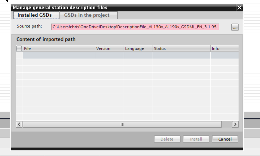
The GSDML management screen appears and the … button is clicked.
Select the GSDML Folder that was downloaded earlier.
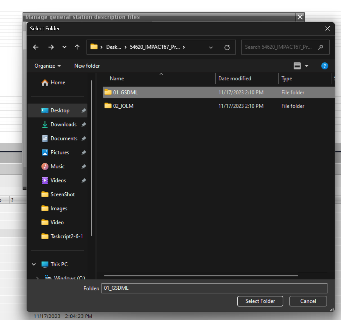
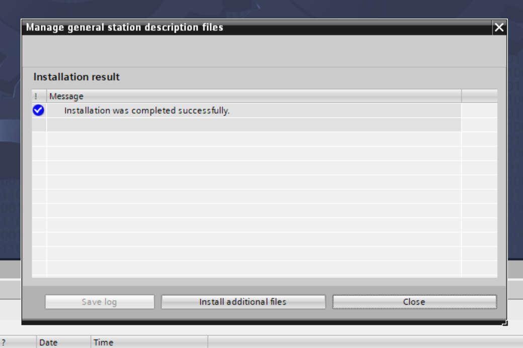
Done!Let’s install the GSDML File.
Done!
Add S7-1500
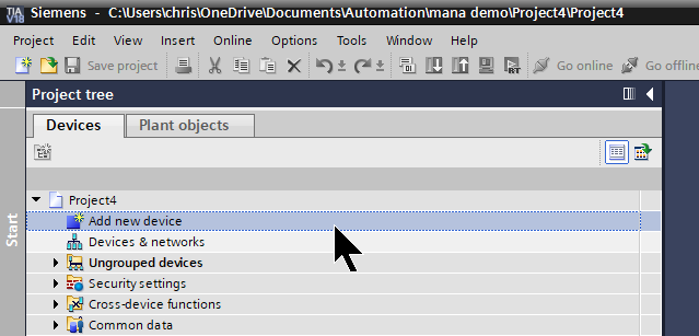
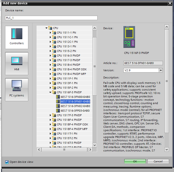
To add S71500; add a new PLC with Add new device.
Controllers>Open the SIMATIC S7-1500 catalog.
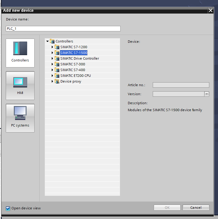
Add the CPU 1516F-3 PN/DP used in this article.
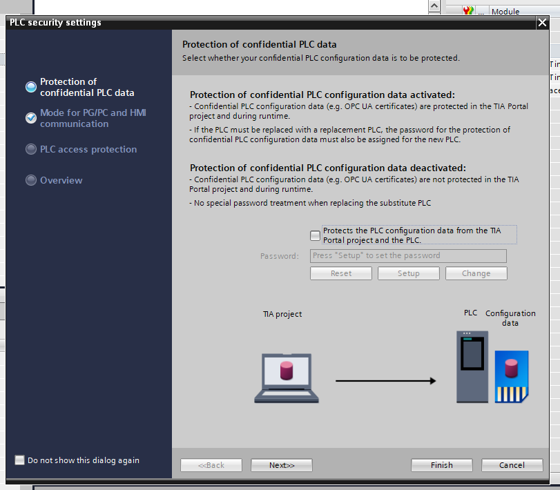
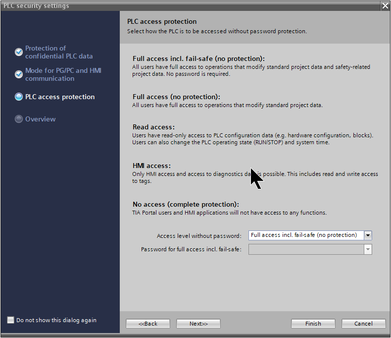
Configure Security
Several security settings are available for the TIAV17 to S71500 CPU.
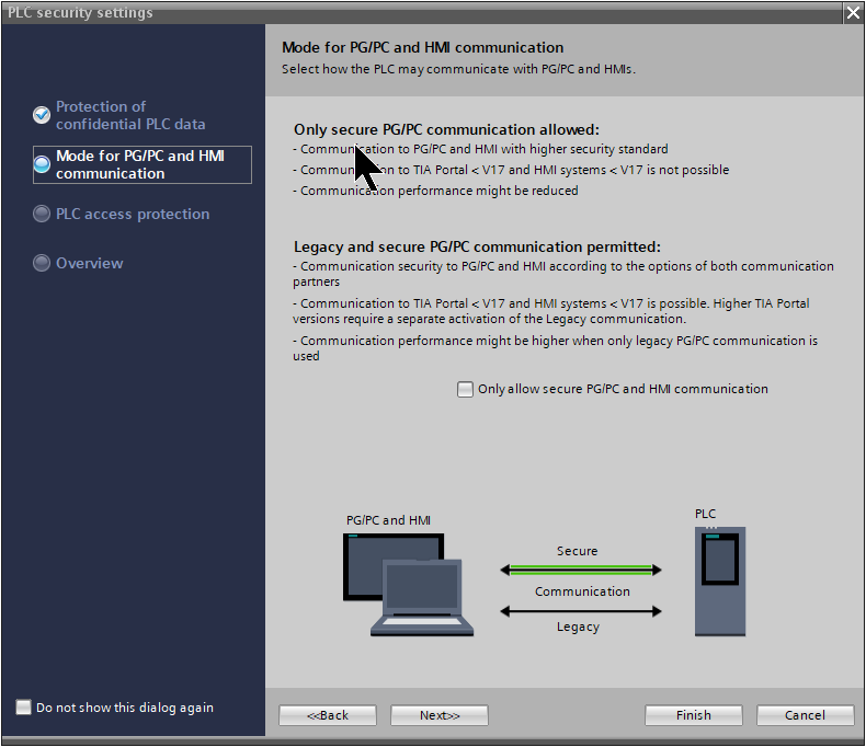
PSet whether G/PC or HMI-only communication should be used and proceed with Next>.
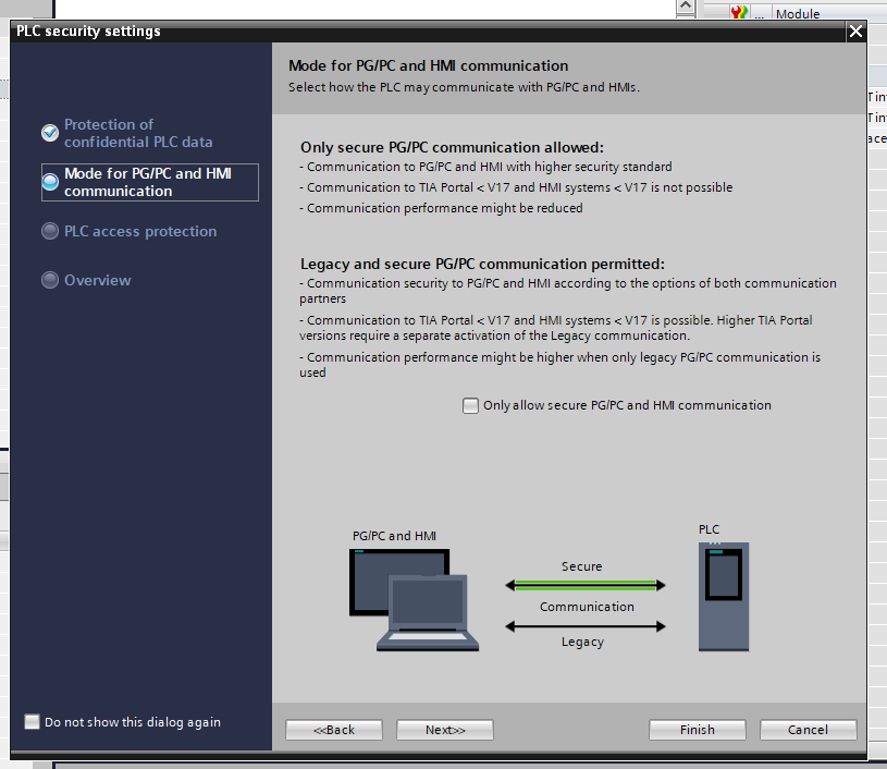
Set whether only security communications are allowed and proceed with Next>>.
Set the level of access to the PLC and proceed with Next>>.
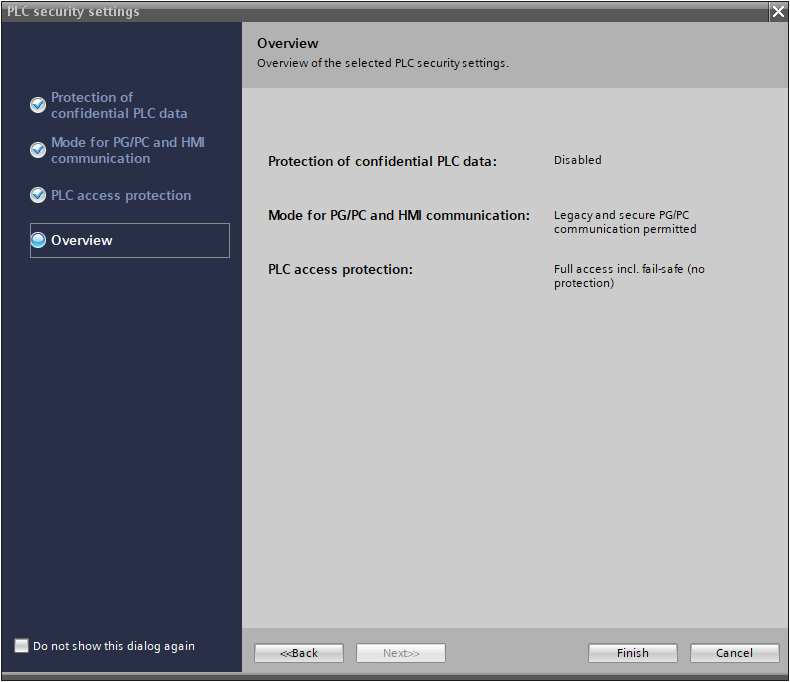
Done!
Configure IP Address
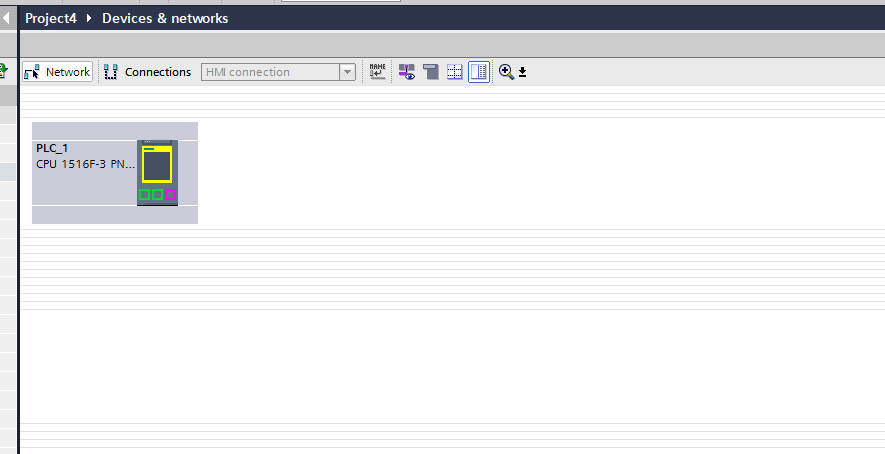
Once the CPU 1516F-3 PN/DP has been added, set the IP address to match the application in PROFINET interface>Etherent address>Set IP address in the project.

Add UR20-FBC-PN-IRT-V2
Add UR20-FBC-PN-IRT-V2 Profinet Coupler.
Switch Network view in TIA.
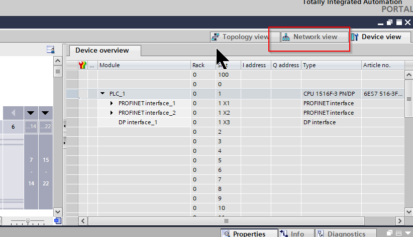
Network devices such as Profinet can be configured on this screen.
You have just added the UR20-FBC-PN-IRT-V2 GSDML File, so drop I/O>Weidmuller Interface>UR20 System>UR20-FBC-PN-IRT-V2Profinet Device.
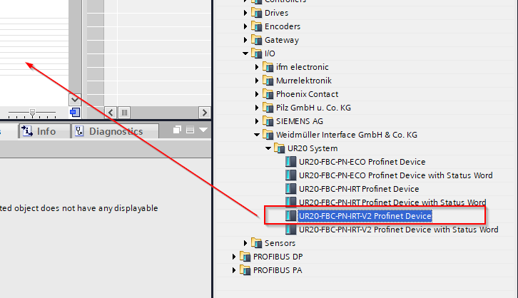
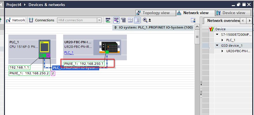
Done!UR20-FBC-PN-IRT-V2 has been added to the project.
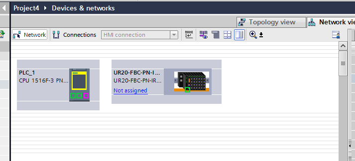
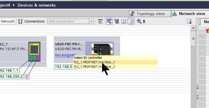
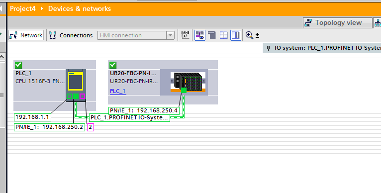
Assign Profinet Network
Next, add UR20-FBC-PN-IRT-V2 to the CPU 1516F-3 PN/DP Profinet.
Select the Profinet network to which you want to connect the UR20-FBC-PN-IRT-V2 from Not assigned.
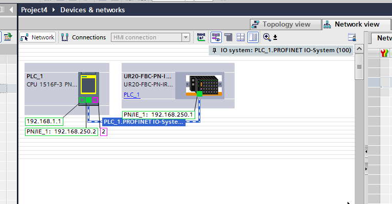
Done!
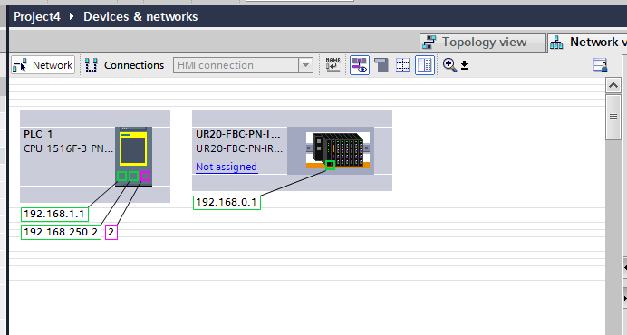
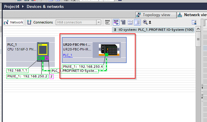
Change IP Address
Set the IP address of the UR20-FBC-PN-IRT-V2 to match your application.
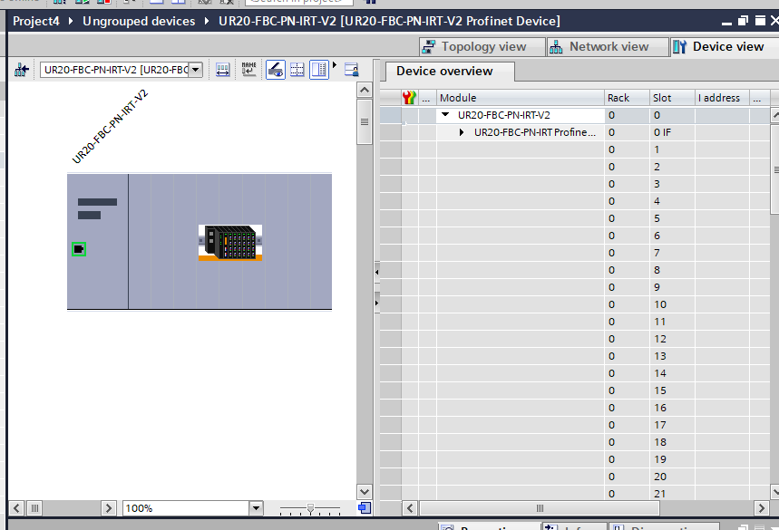
Configure UR20
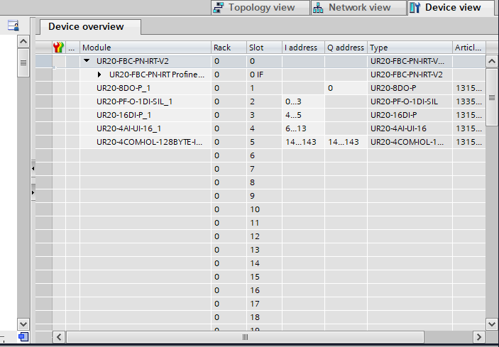
The next step is to build each Slot installed in UR20-FBC-PN-IRT-V2.
The screen changes to the UR20-FBC-PN-IRT-V2 configuration screen.
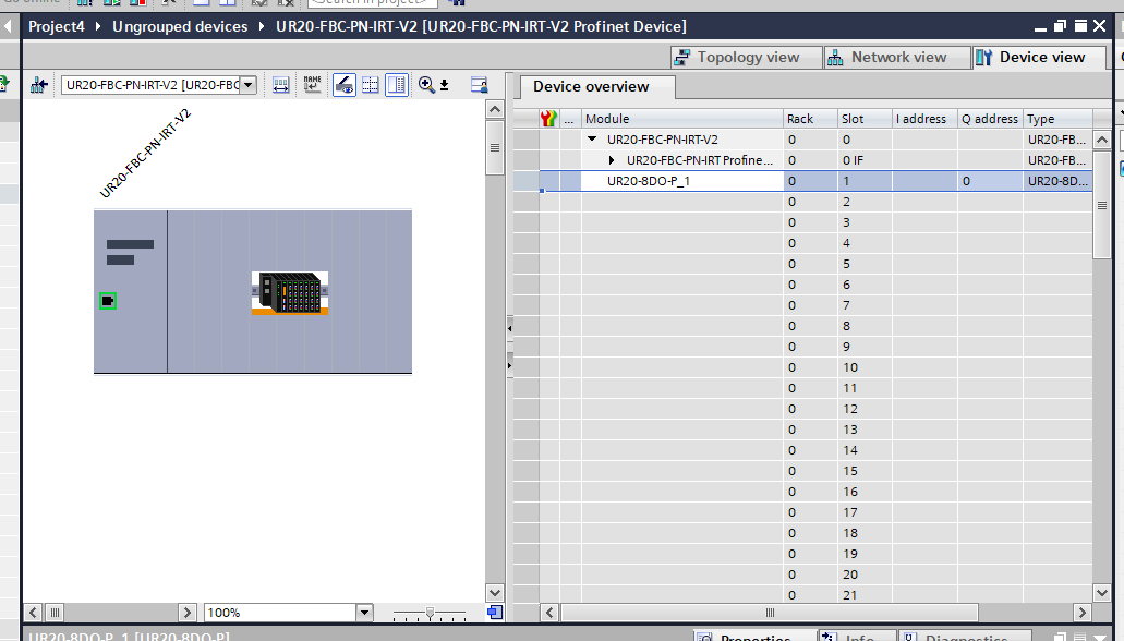
Insert UR20-8DO-P
Add UR20-8DO-P output module.
Add Module>DO>UR20-8DO-P.
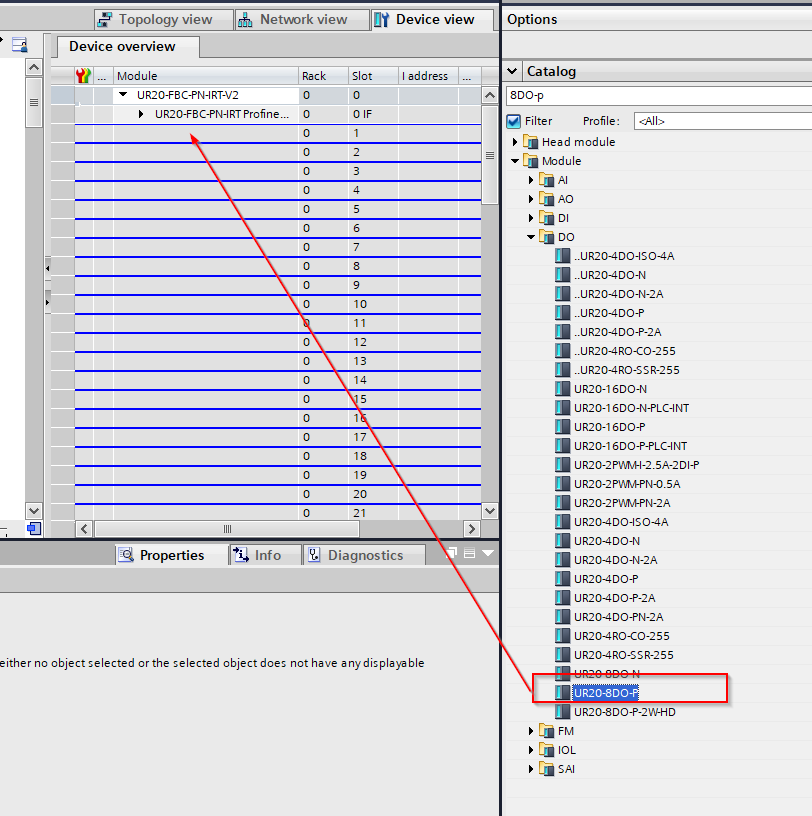
Done!
Insert UR20-PF-O-1DI-SIL
Add UR20-PF-O-1DI-SIL safety module.
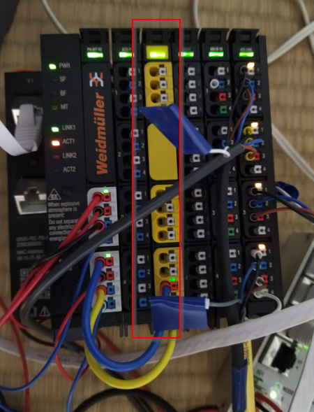
Add Module>DI>UR20-PF-O-1DI-SIL.
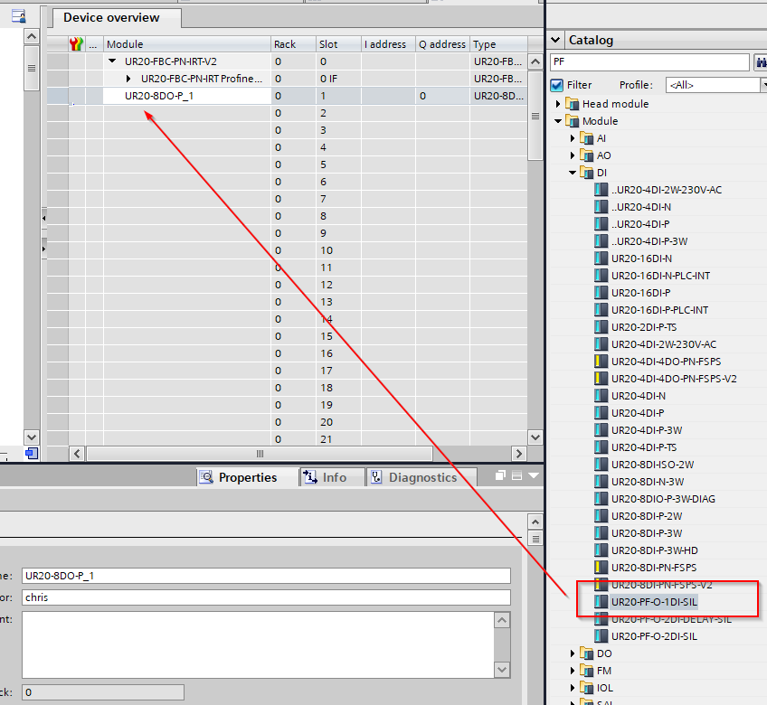
Done!
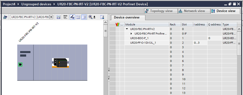
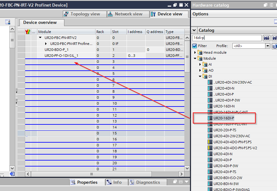
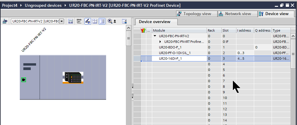
Insert UR20-16DI-P
Add UR20-16DI-P input module.
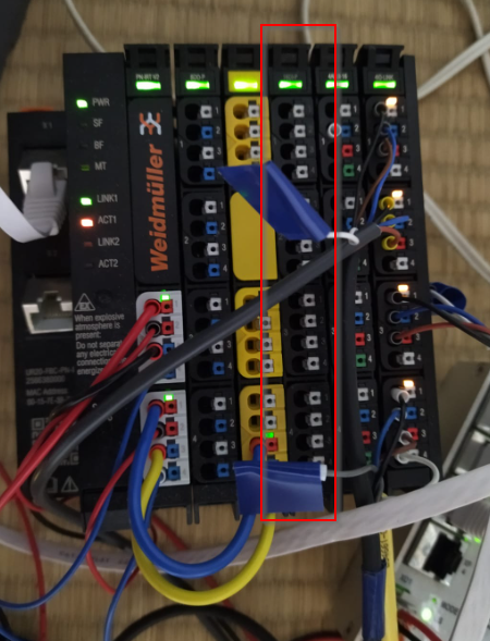
Add Module>DI>UR20-PF-O-1DI-SIL.
Done!
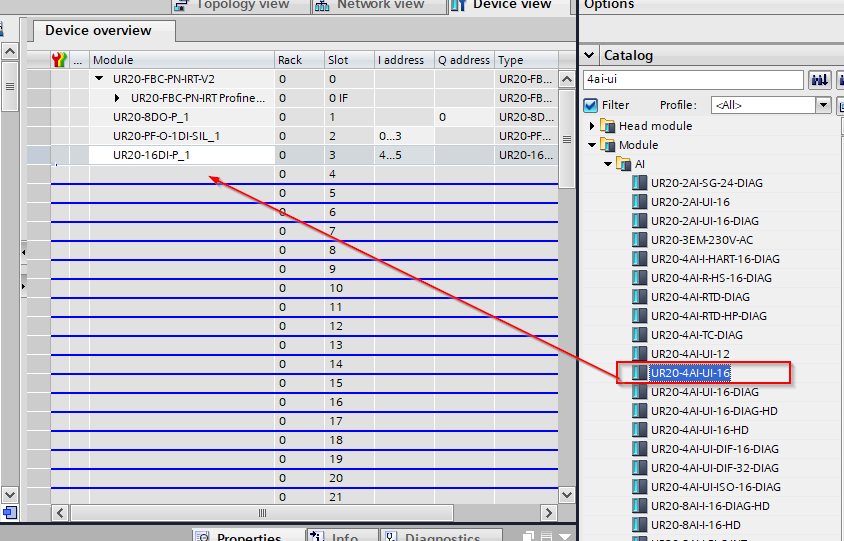
Insert UR20-4AI-UI-16
Add UR20-4AI-UI-16L analogue input module.
Add Module>AI>UR20-4AI-UI-16.
Insert UR20-4COMHOL-128BYTE-INOUT
Add UR20-4COM-IO-LINK IOLINK module.
Add Module>IOL>UR20-4COMHOL-128BYTE-INOUT.
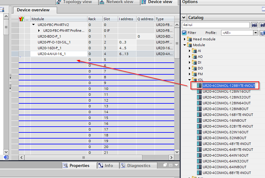
Done!
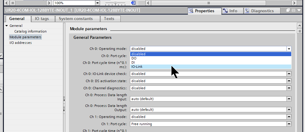
Next, set the IOLINK parameters in Module parameters.
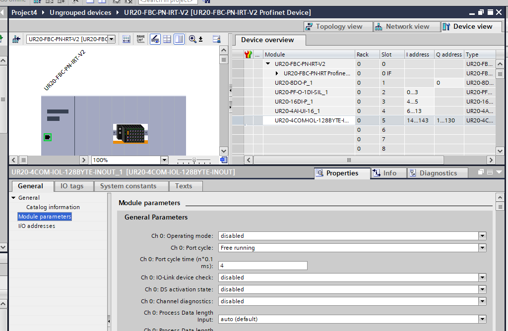
Operation Mode
Change the Operation Mode of each Port to IO-Link.
Input/Output Length
The next step is to set the input/output data size for each Port.
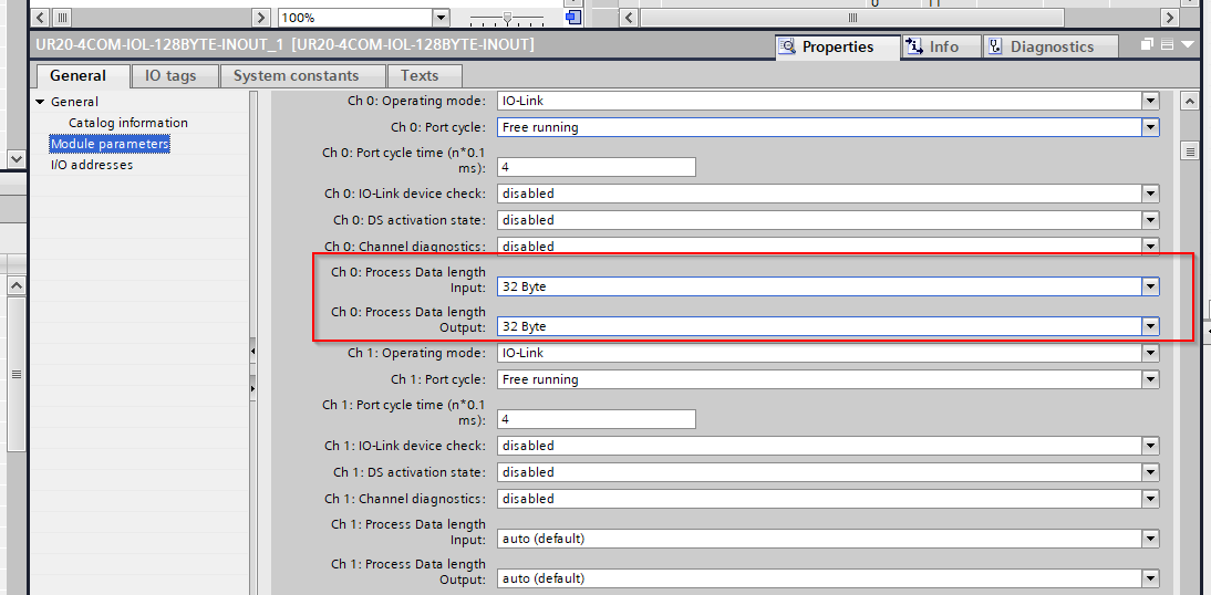
Ch0
Channel 0 is connected to the E3AS-HL500LMN, so set Input Data=32 Bytes and Output Data=0 Bytes.
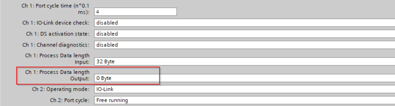
Ch1
Channel 1 is connected to E3E-X3B4-IL3-2M, so set Input Data=32 Bytes and Output Data=0 Bytes.
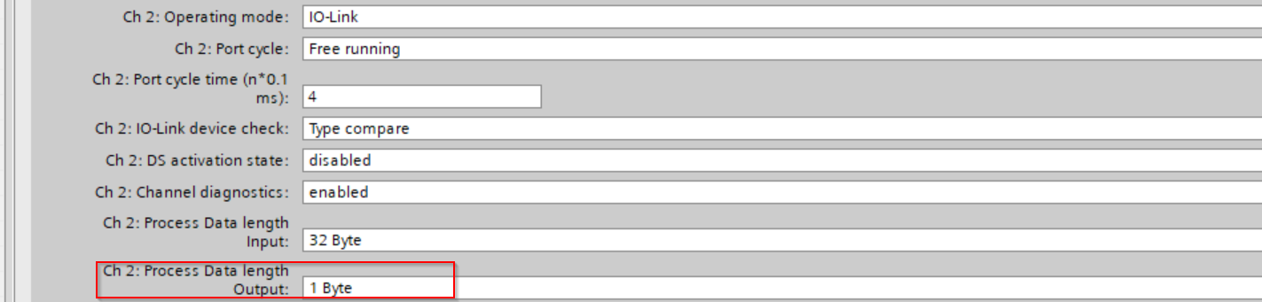
Ch2
Channel 2 is connected to the Smart Connector, so set Input Data=32 Bytes and Output Data=1 Bytes.
Ch3
Channel 3 is connected to 59507, so set Input Data=32 Bytes and Output Data=2 Bytes.
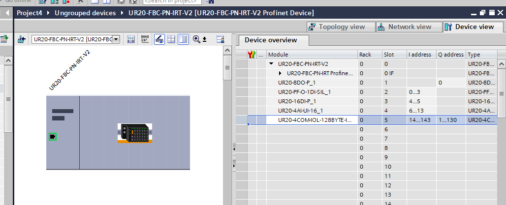
Result
Finally, set the I/Q Address for each module.
Program
The next step is programming.
DUT
Let’s start by defining the structure. c
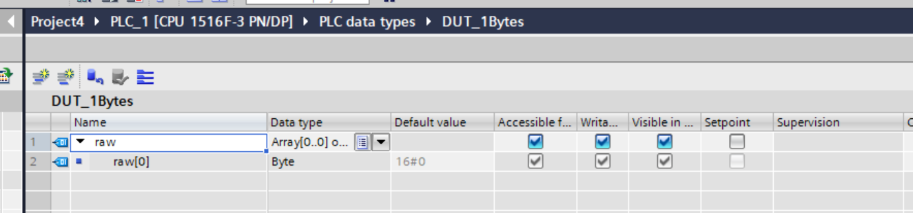
DUT_1Bytes
This is a 1Bytes structure, which is used for Tag definitions in Process Data and as input/output for Function Block.
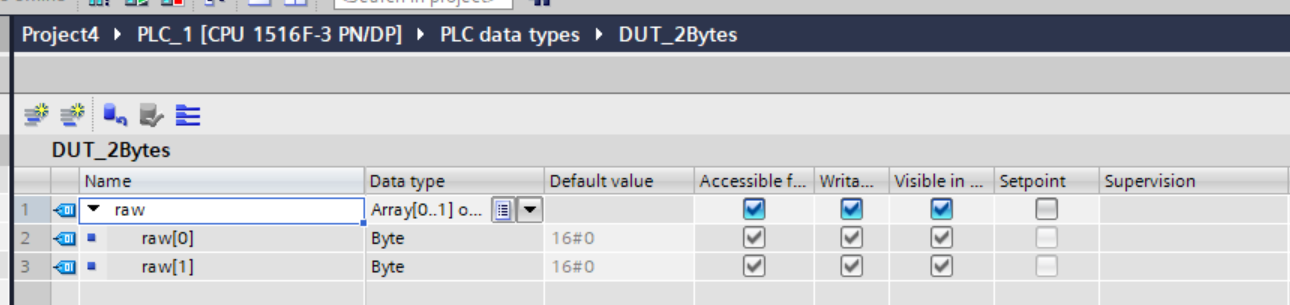
DUT_2Bytes
This is a 2Bytes structure, which is used for Tag definitions in Process Data and as input/output for Function Block.
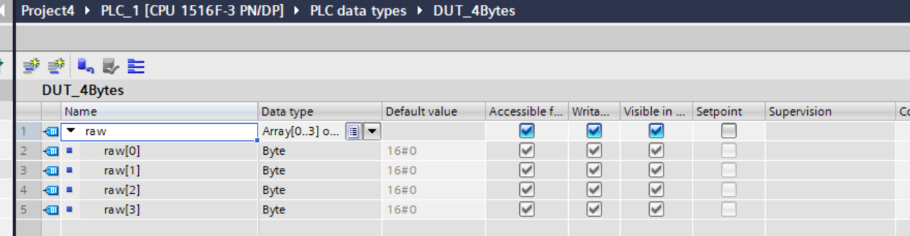
DUT_4Bytes
This is a 4Bytes structure, which is used for Tag definitions in Process Data and as input/output for Function Block.
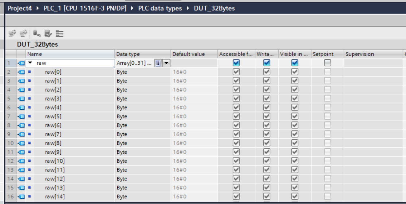
DUT_32Bytes
This is a 32 Bytes structure, which is used for Tag definitions in Process Data and as input/output for Function Block.
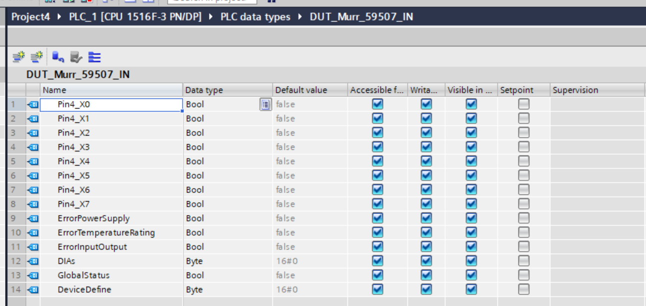
DUT_Murr_59507_IN
This is the Port-based input data structure for Murrelektronik’s MVP8-P3 DIO8 8xM8-3 IOLA12 E 59507.
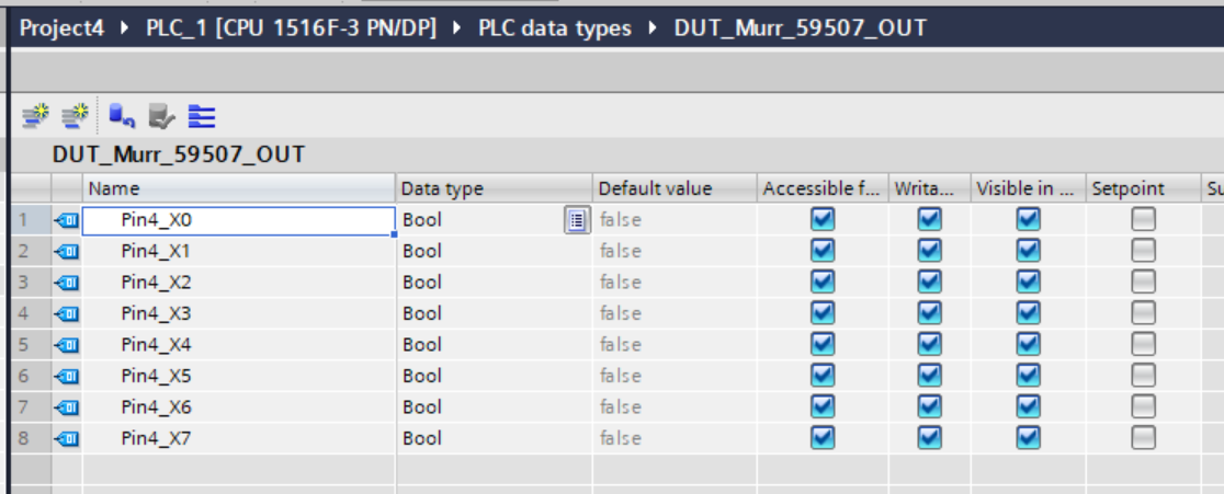
DUT_Murr_59507_OUT
This is the Port-based output data structure for Murrelektronik’s MVP8-P3 DIO8 8xM8-3 IOLA12 E 59507.
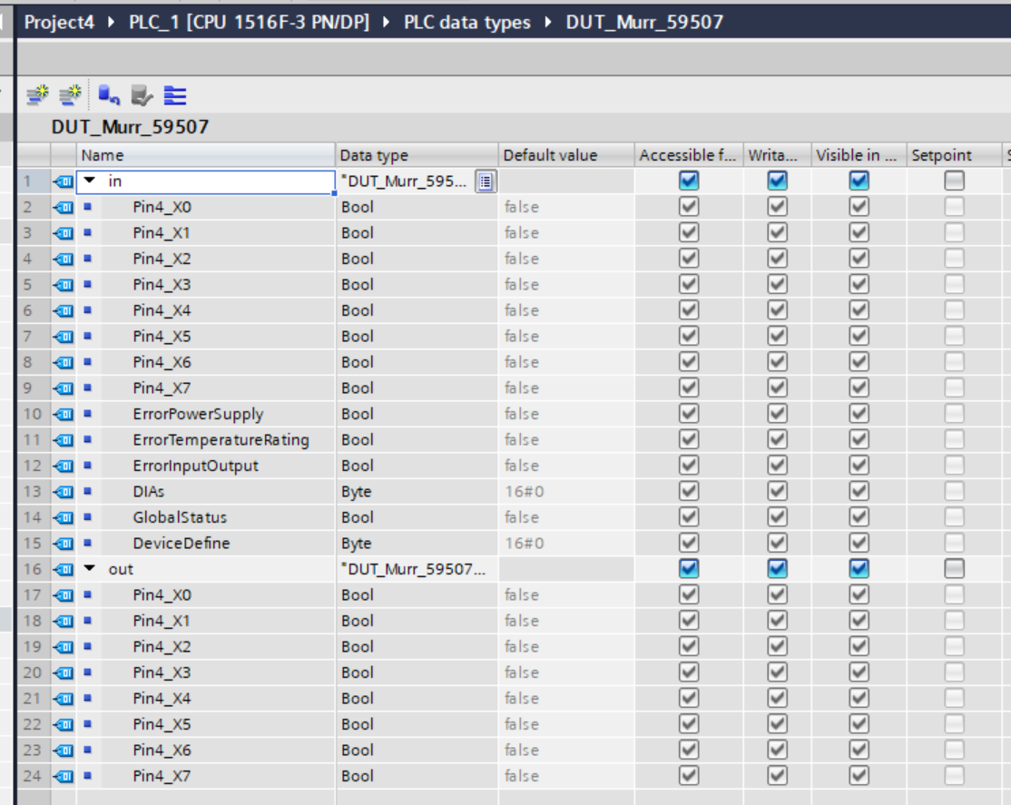
DUT_Murr_59507
This is the structure that is passed to the control FB of the Murrelektronik MVP8-P3 DIO8 8xM8-3 IOLA12 E 59507.
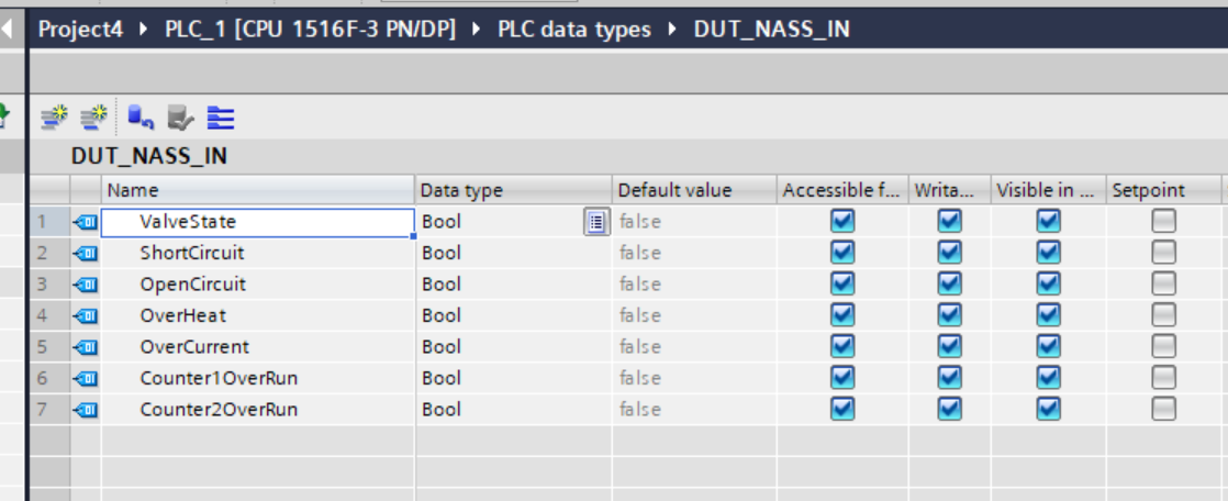
DUT_NASS_IN
This is the structure of the input data for the Nass Magnet Smart Connector.
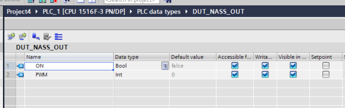
DUT_NASS_OUT
This is the structure of the Nass Magnet Smart Connector output data.
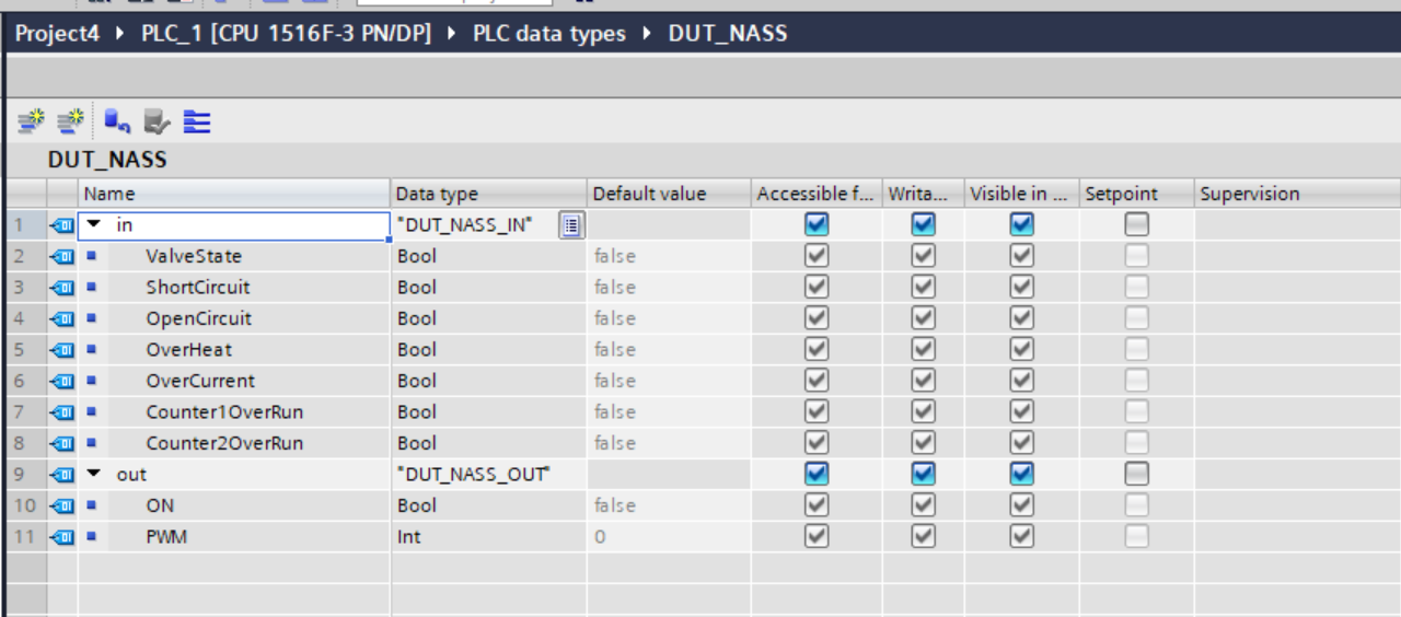
DUT_NASS
This is the structure that is passed to the control FB of the Nass Magnet Smart Connector.
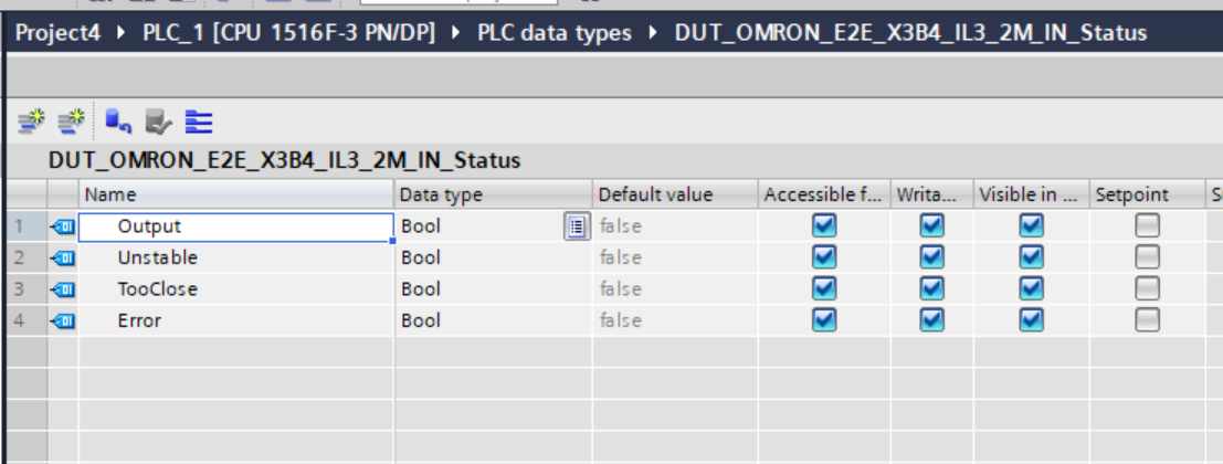
DUT_OMRON_E2E_X3B4_IL3_2M_IN_Status
This is the input data structure for the OMRON E2E-X3B4-IL3-2M.
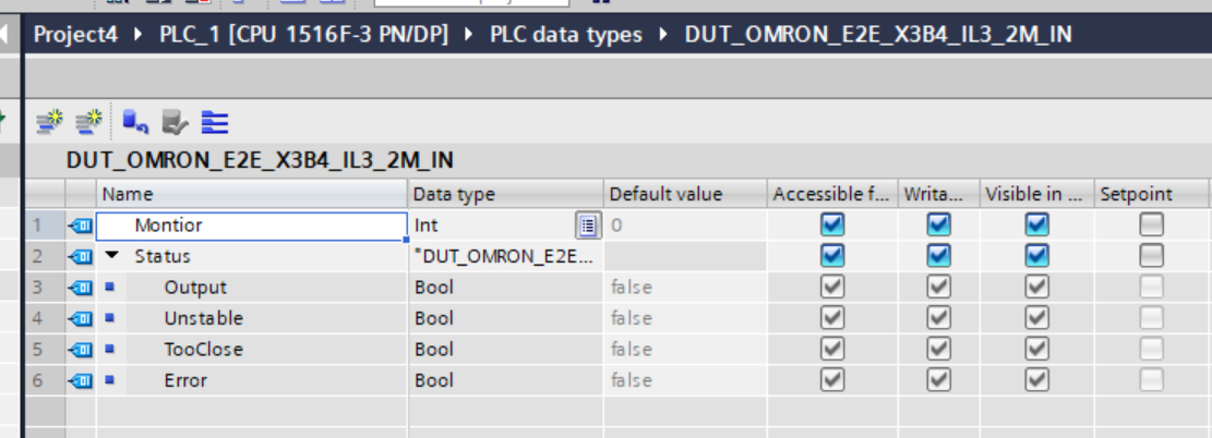
DUT_OMRON_E2E_X3B4_IL3_2M_IN
This is the structure that is passed to the control FB of the OMRON E2E-X3B4-IL3-2M.
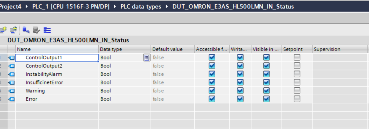
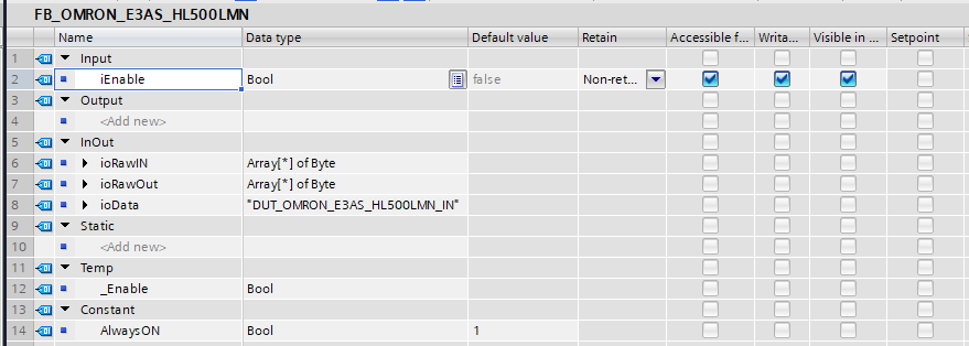
DUT_OMRON_E3AS_HL500LMN_IN_Status
This is the input data structure for the OMRON E3AS-HL500LMN.
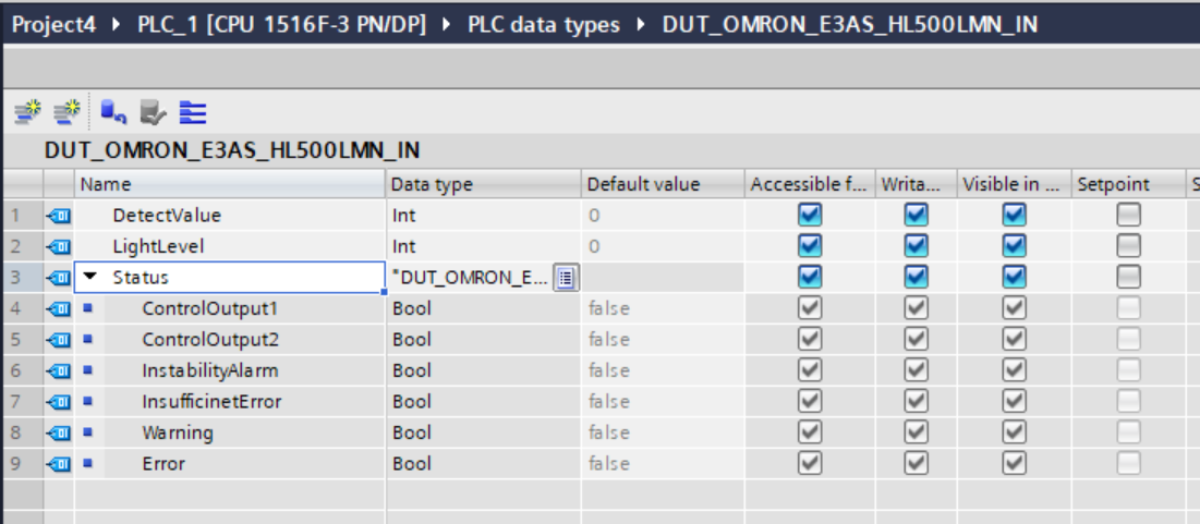
DUT_OMRON_E3AS_HL500LMN_IN
This is the structure that is passed to the control FB of the OMRON E3AS-HL500LMN.
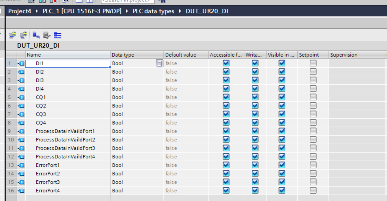
DUT_UR20_DI
This is the input data structure of the UR20-4COM-IO-LINK.
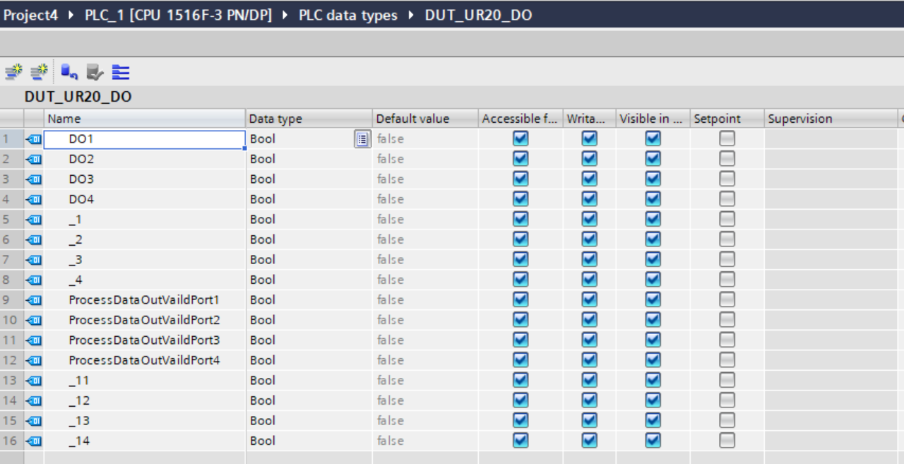
DUT_UR20_DO
This is the structure for the output data of the UR20-4COM-IO-LINK.
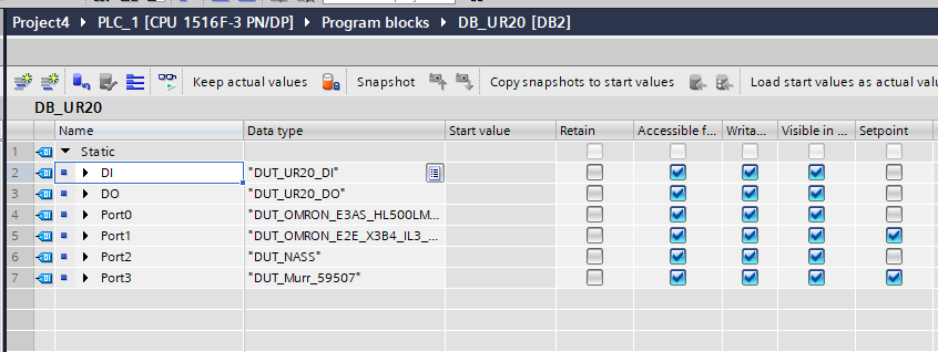
DB_UR20
This is the UR20-4COM-IO-LINK structure.
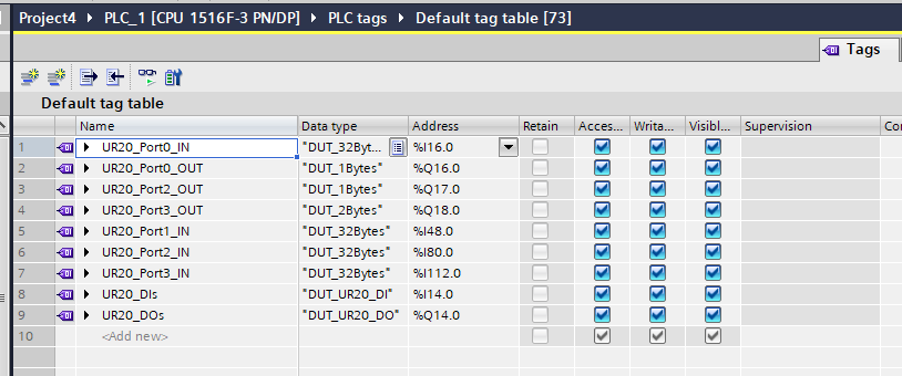
Tags
Next, define the Tags according to the IO address.
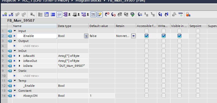
FB_Murr_59507
This is a Function Block for Murrelektronik’s MVP8-P3 DIO8 8xM8-3 IOLA12 E 59507.
Interface
Network1
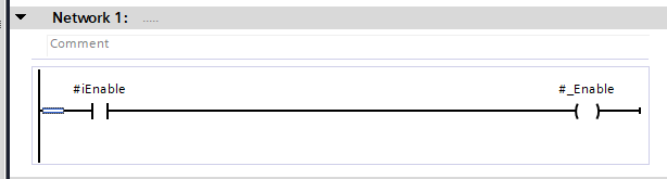
The signal is not used in this case, but it is an Enable signal used in the internal FB.
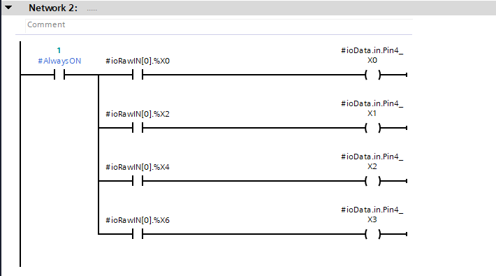
Network2
This one retrieves input data according to Mapping.
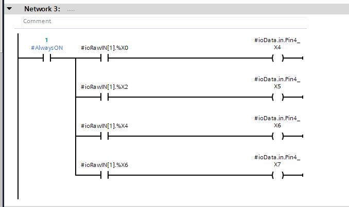
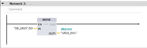
Network3
This one retrieves input data according to Mapping.
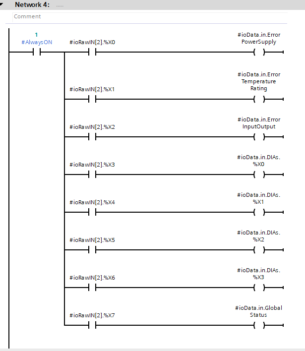
Network4
This one gets the state of the module according to Mapping.
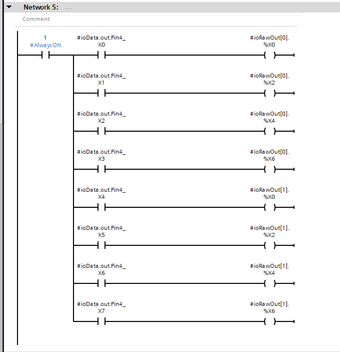
Network5
This output is tailored to Mapping.
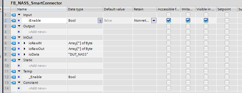
FB_NASS_SmartConnector
This is the Function Block for the Nass Magnet Smart Connector.
Interface
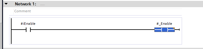
Network1
This is the Enable signal used by the internal FB.
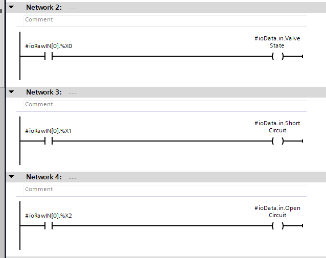
Network2-4
This one gets the state of the device according to Mapping.
Network5-8
This one gets the state of the device according to Mapping.
Network9
This is the output control for the Nass Magnet Smart Connector.
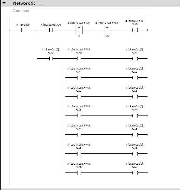
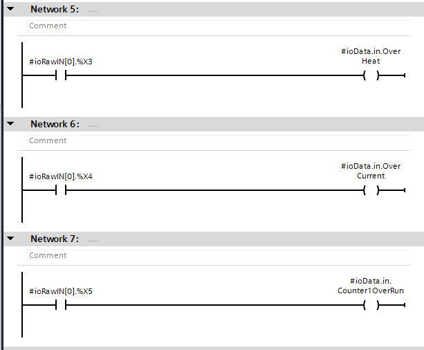
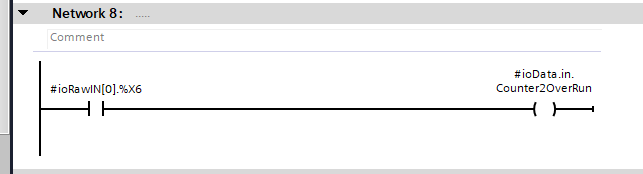
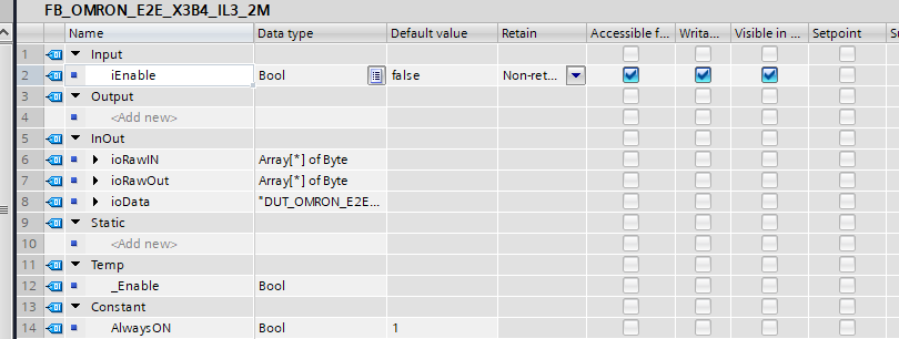
FB_OMRON_E2E_X3B4_IL3_2M
This is an OMRON E2E-X3B4-IL3-2M Function Block.
Interface
Network1
The signal is not used in this case, but it is an Enable signal used in the internal FB.
Network2
Network3
FB_OMRON_E3AS_HL500LMN
Interface
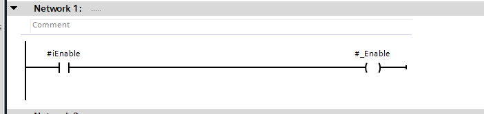
Network1
This one gets the detection distance according to Mapping.
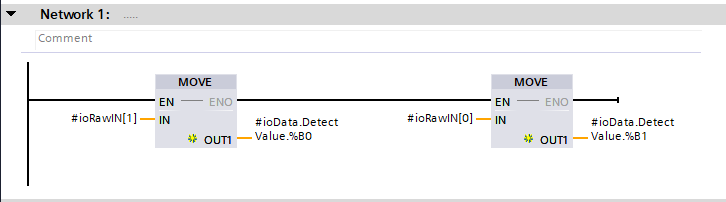
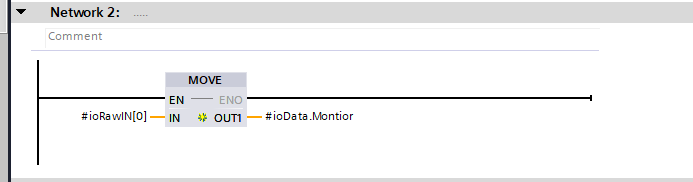
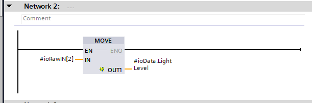
Network2
This one gets the Lighting Level according to Mapping.
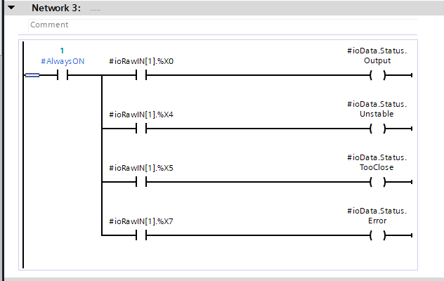
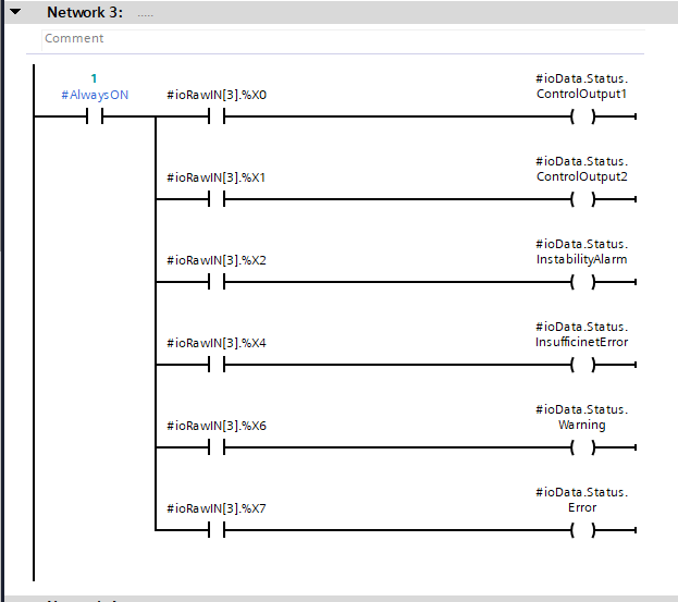
Network3
This one gets the state of the device according to Mapping.
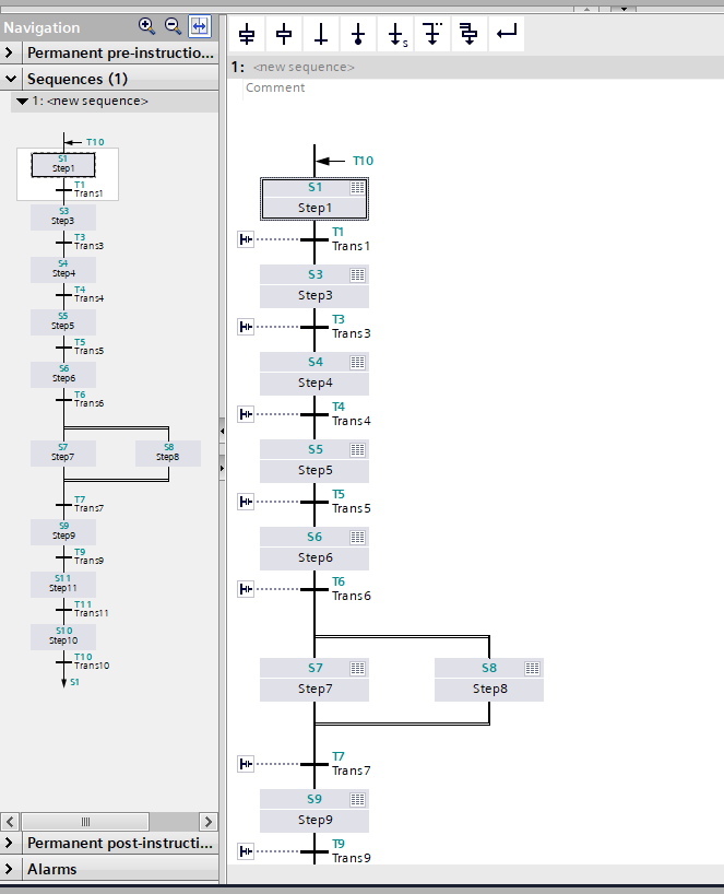
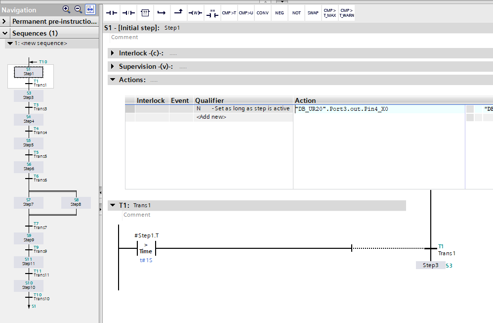
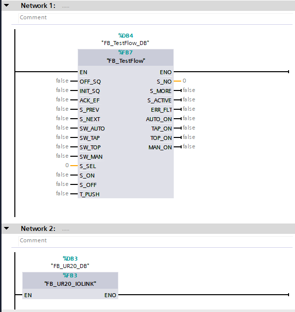
FB_TestFlow
The Function Block here is a Graph that turns on the outputs of Murrelektronik’s MVP8-P3 DIO8 8xM8-3 IOLA12 E 59507 one by one in sequence.
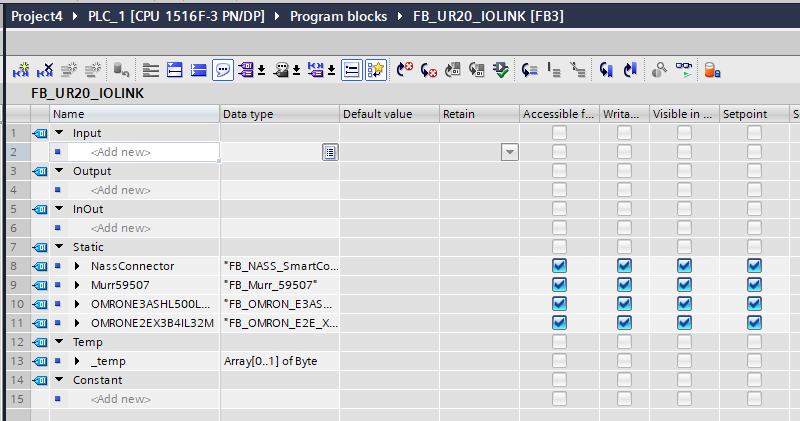
FB_UR20_IOLINK
This is the Function Block that controls the UR20-4COM-IO-LINK.
Interface
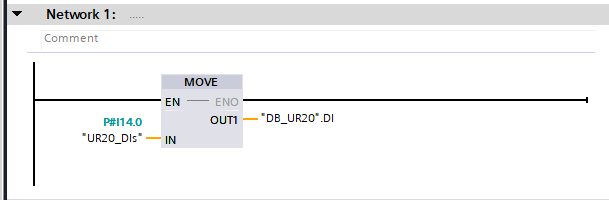
Network1
This one transfers Process IO to the Data Block.
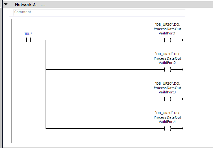
Network2
This one enables the IOLINK output data.
Network3
This is a program that transfers the output data of the Data Block to Process IO.
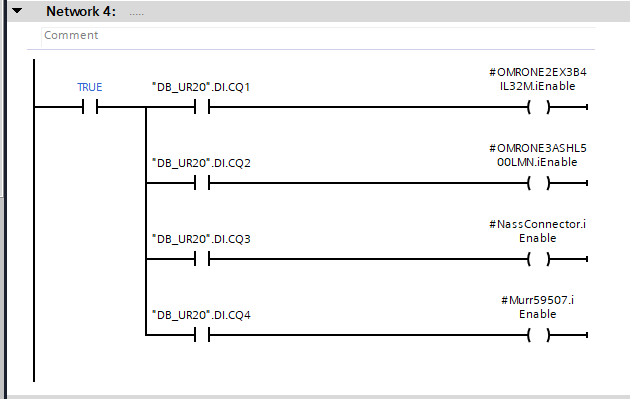
Network4
This one enables the Enable signal only when each Port communicates Ok with the IOLINK device.
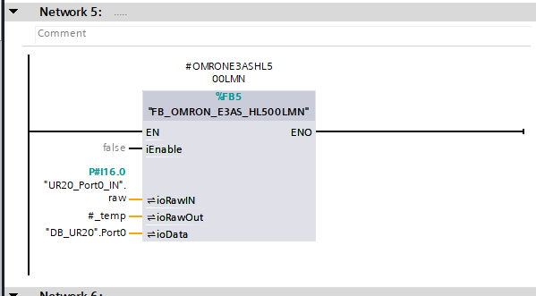
Network5
Call the Function Block of the OMRON E3AS-HL500MN created earlier.
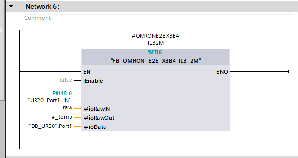
Network6
Call the Function Block of the OMRON E2E-X3B4-IL3-2M created earlier.
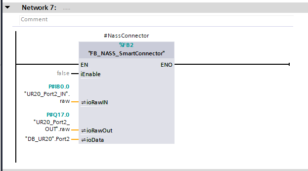
Network7
Call the Function Block of the Smart Connector you have just created.
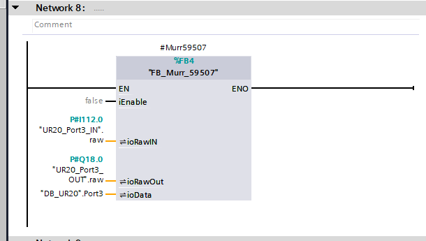
Network8
Call the Function Block of Murrelektronik’s MVP8-P3 DIO8 8xM8-3 IOLA12 E 59507 created earlier.
OB1
Finally, OB1 calls the required FB.
Download
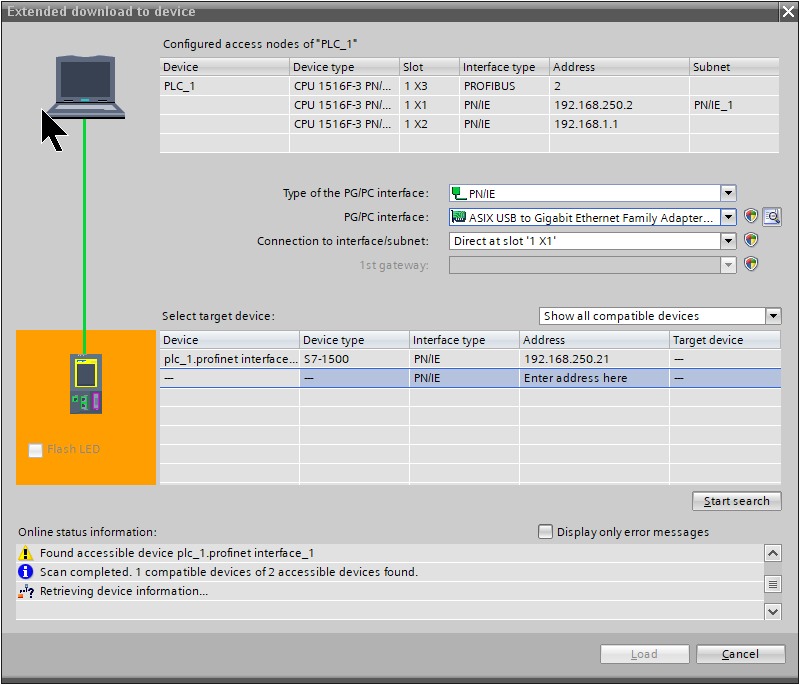
The last step is to Download the project to the CPU.

Select the appropriate Network Interface and use Start Search to search for the CPU.
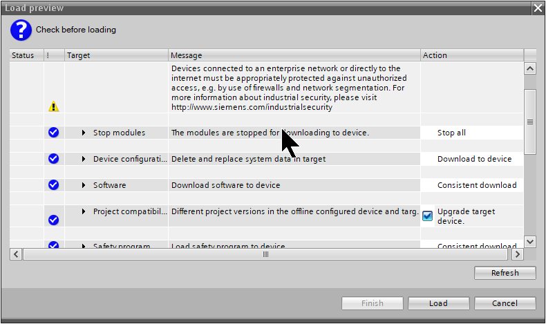
Then select where you want to download the project and use >Load to download the project.
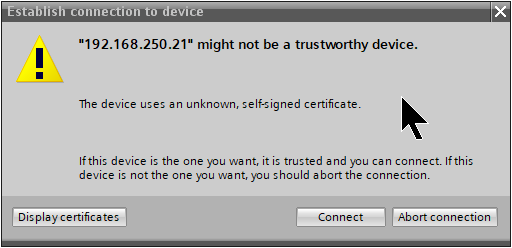
Proceed with Connect.
Download the project.
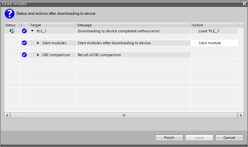
Just a second..

Done!
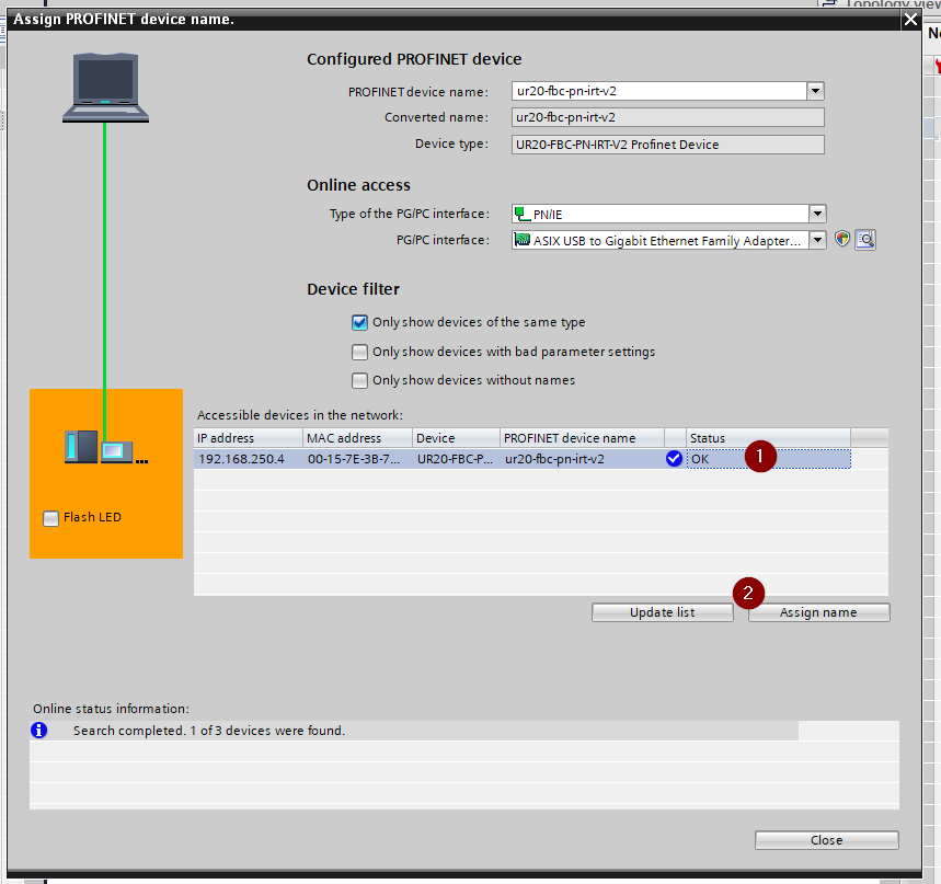
Assign Name
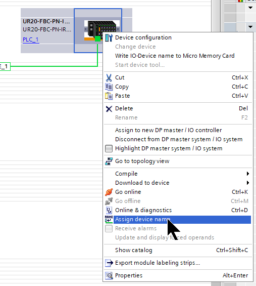
In a Profinet network, a Device name must be assigned to each Profinet device.
Select the Profinet Coupler > right-click > Assign device name.
Update List.
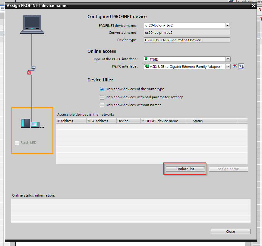
Assign a device name.
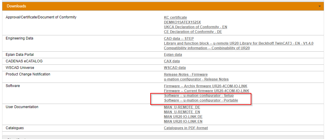
u-mation configurator
Before checking the actual IOLINK device data, Weidmüller offers a free configuration tool. Download it at the link below.
https://catalog.weidmueller.com/catalog/Start.do?localeId=en&ObjectID=1315740000
Start the Tool
Start the software.
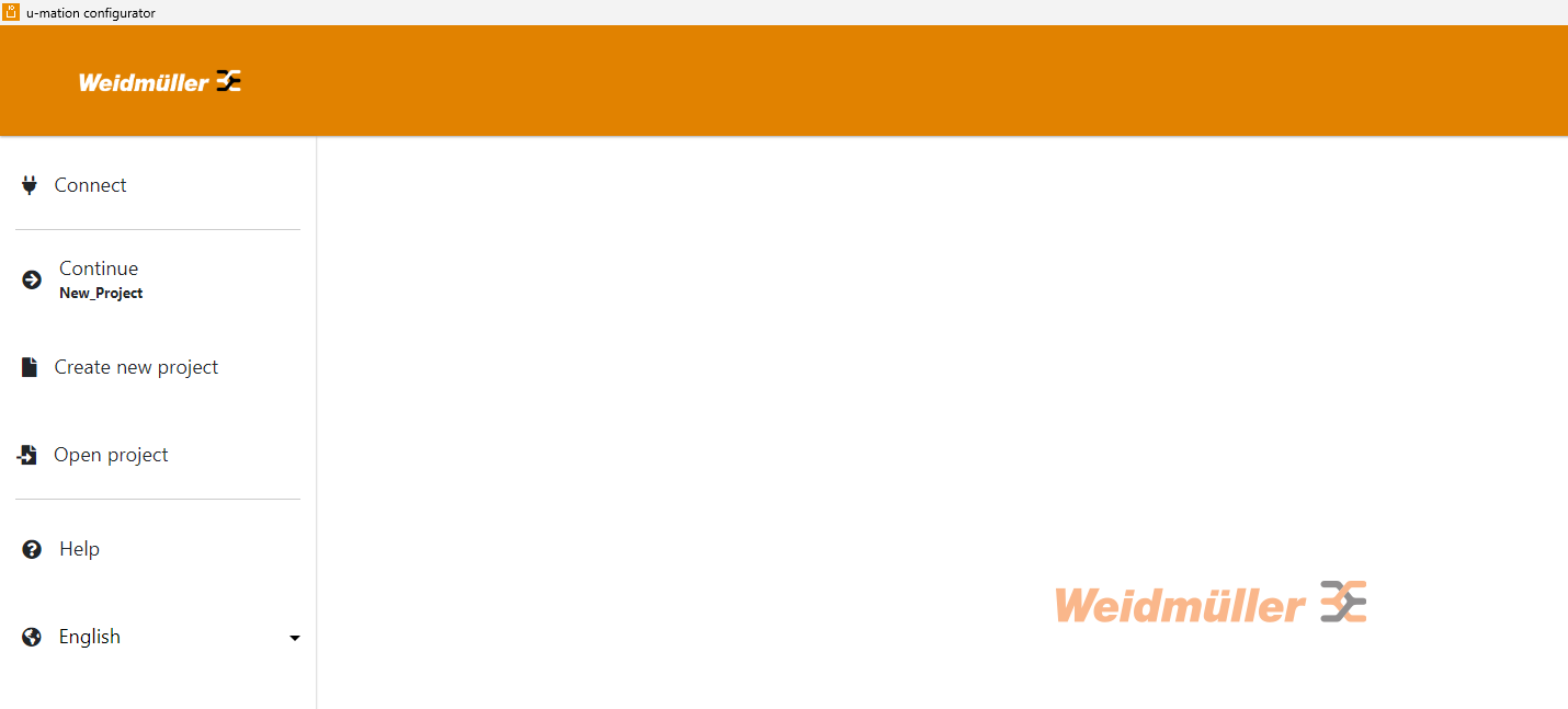
Connect
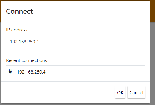
Click Connect to connect with the Profinet Coupler.
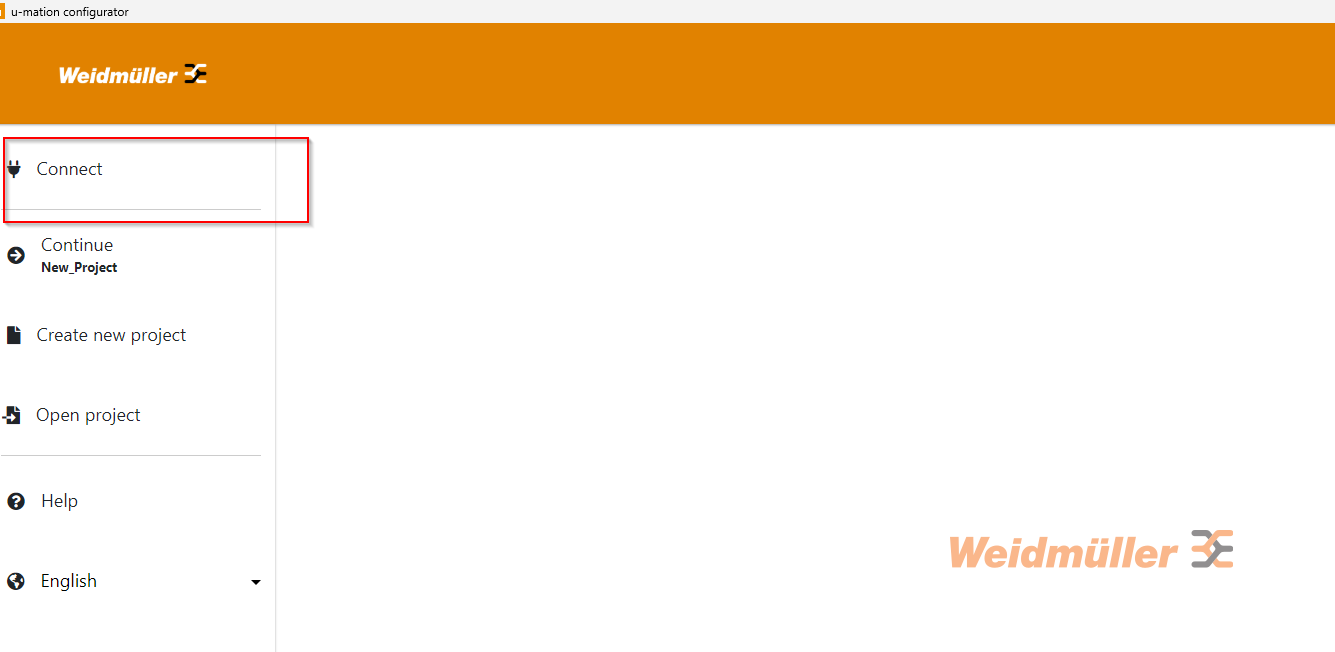
This is the IP address configured for the Profinet Coupler.
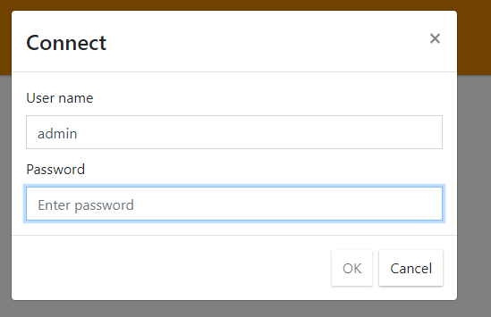
You will be prompted for User Name and Password, in Default,
- User name: admin
- Password: Detmold
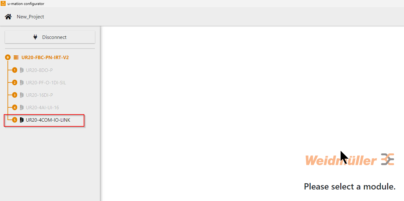
Done!The tool and Coupler are now connected, and the UR20-4COM-IO-LINK is recognised.
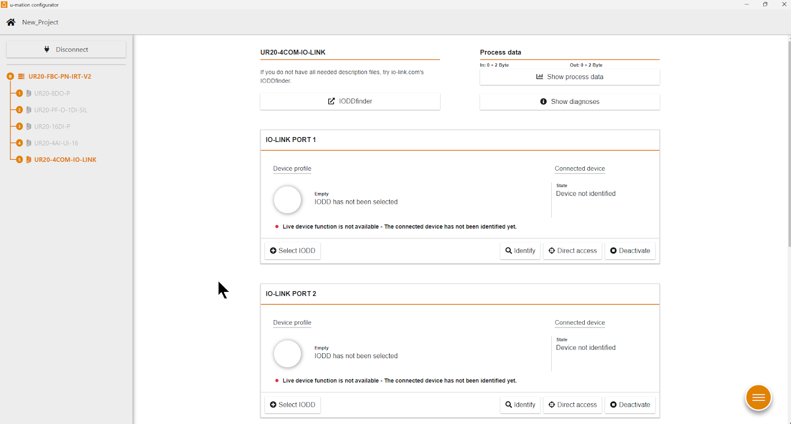
Now click on UR20-4COM-IO-LINK.
Check each Port of the UR20-4COM-IO-LINK and the connection status, etc.
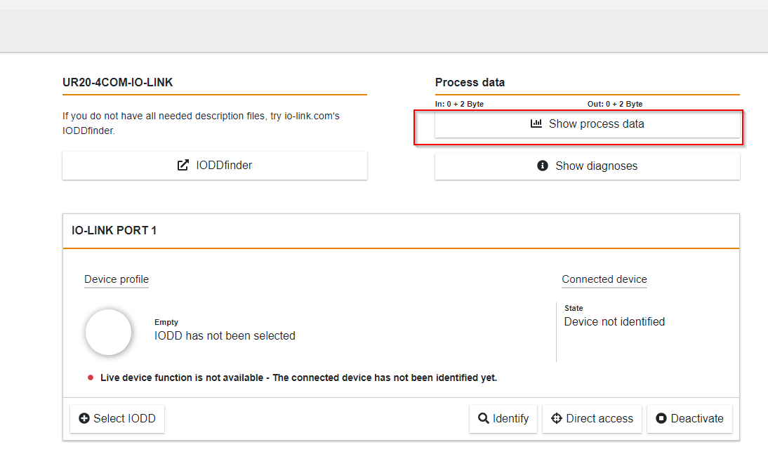
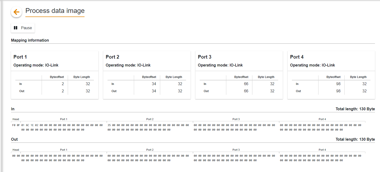
Show Process Data
Click Show process data to see the current Process data.
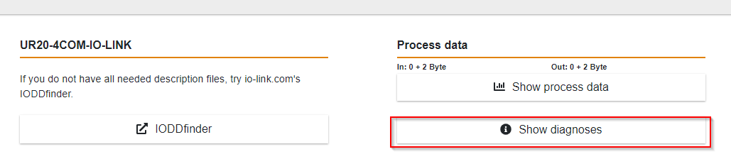
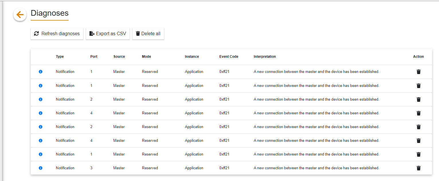
Show diagnoses
Click Show diagnoses to check the diagnostic status of the module.
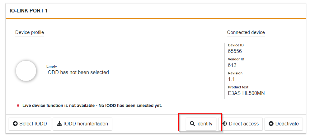
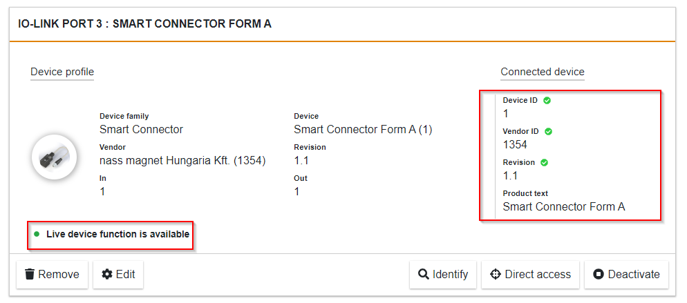
Idenifty
Use the Idenifty function to check information on the IO-Link devices currently connected to each Port.
Find IODD
Let the tool load the IODD File; clicking on IODD herunterladen will automatically take you to the IODD Finder webpage.
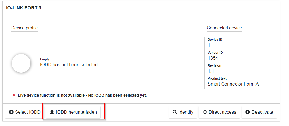
Enter the IO-Link device type there.
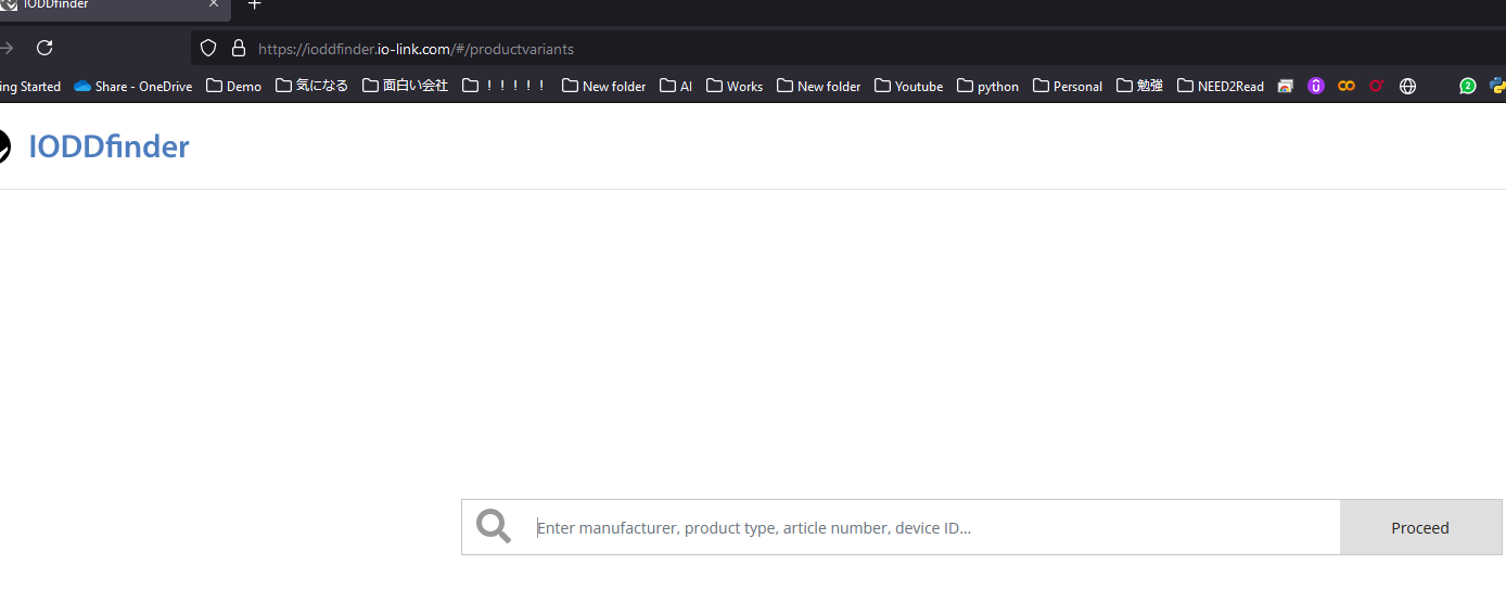
In the example below, we searched for the Nass Magnet Smart Connector.
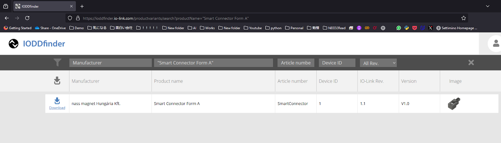
Click Download to download the IODD File.
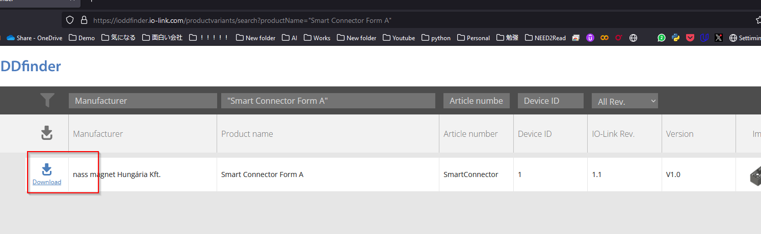
Done!
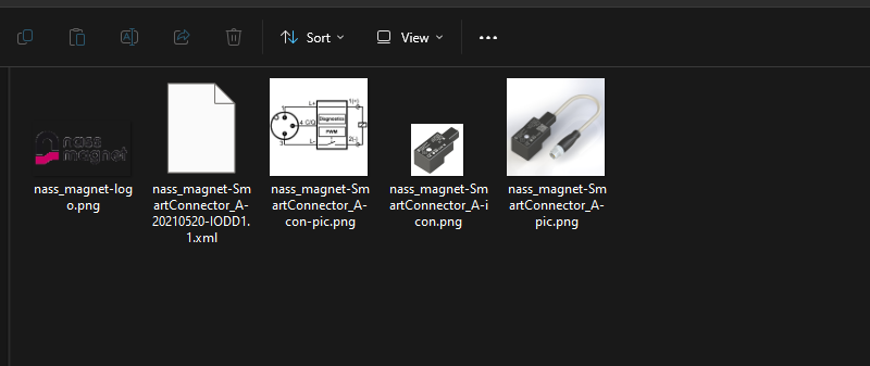
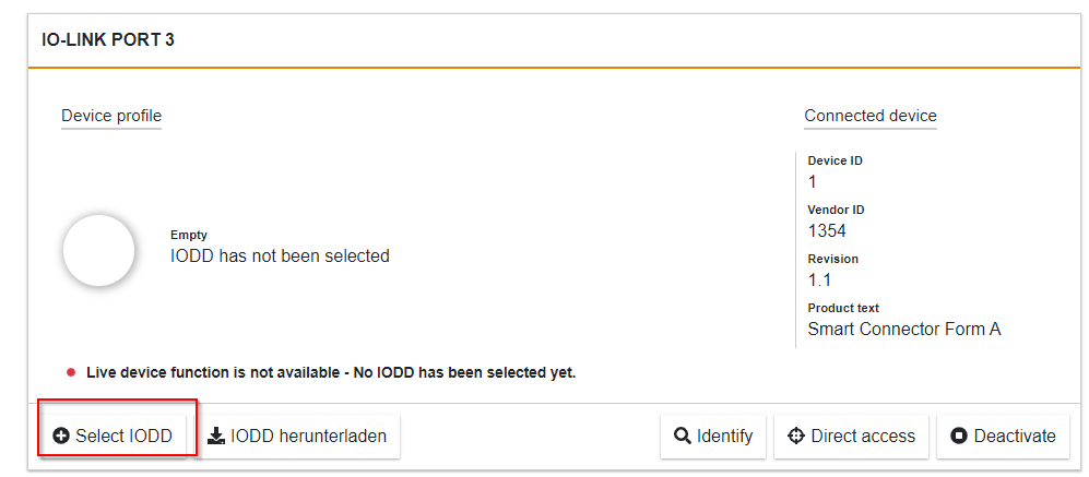
Load IODD
Next, click Select IODD to load the IODD File into the tool.
Select the File you have just downloaded.
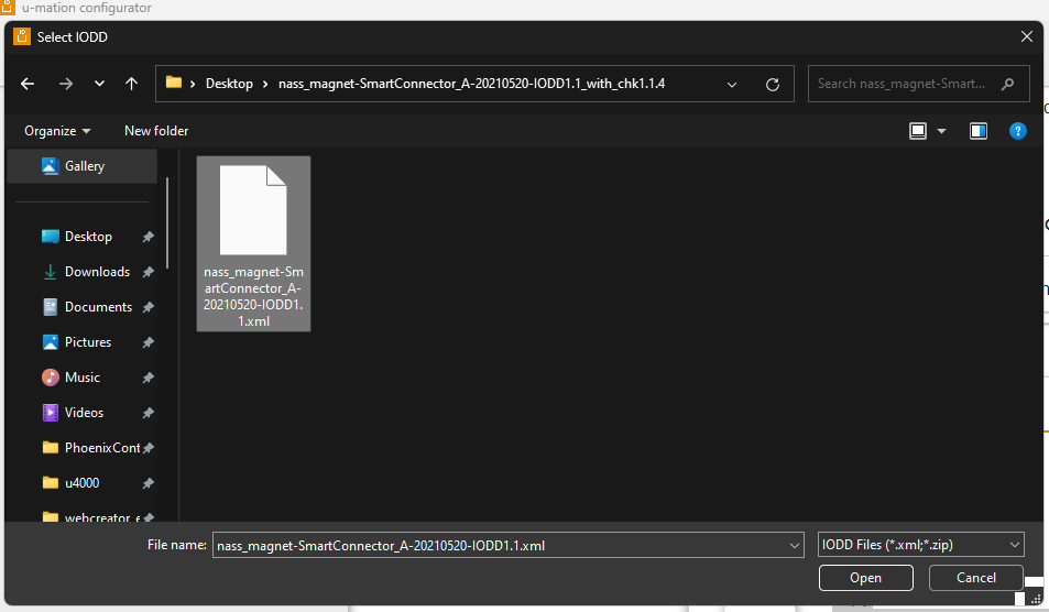
Done!
Edit
Next, click on the Edit button to change the parameters of the IO-Link device, for example.
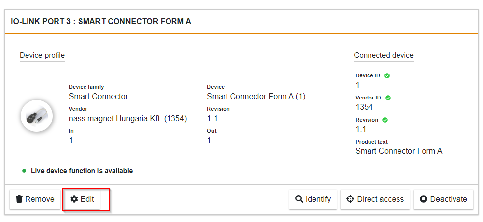
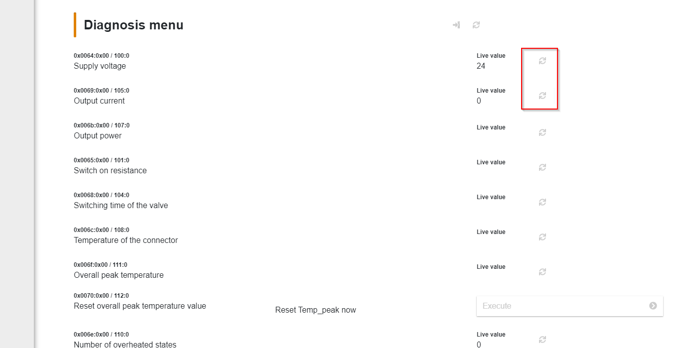
All parameters and status of the relevant IO-Link device could be checked.
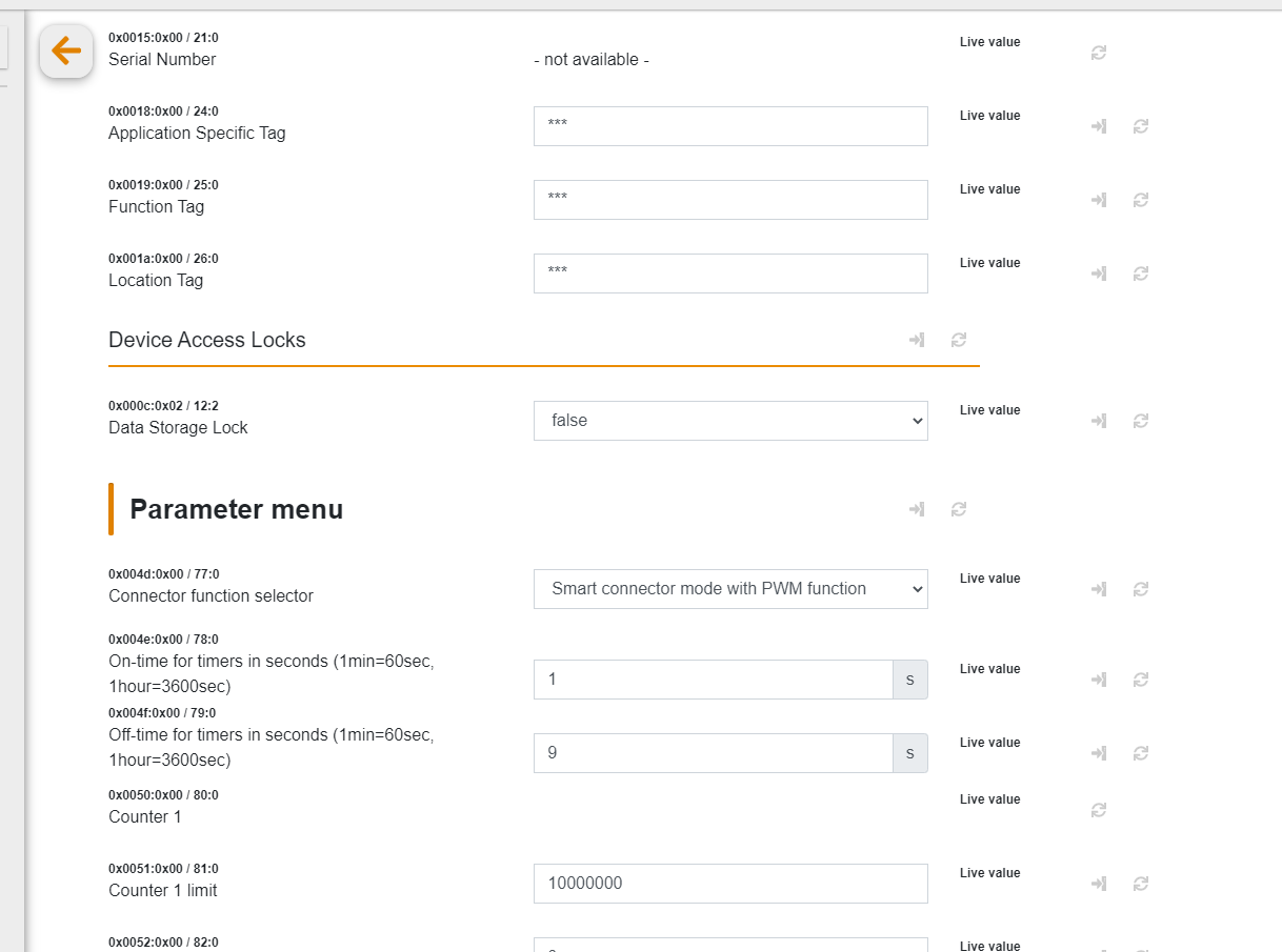
The current values can be updated by clicking on the Reflesh button next to the Diagnostic Menu.
Result
Connect TIAs and CPUs with Go Online.
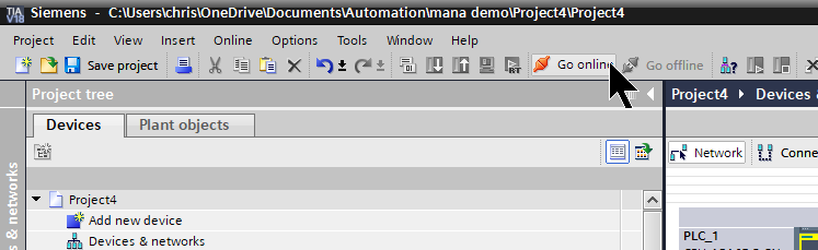
Done!Communication between CPU 1516F-3 PN/DP and Profinet Coupler is now established.
This is the LED and Display state when the PLC and Coupler normalise.

You can check the operation in this video.
You can also Download the project at this Link.
https://github.com/soup01Threes/Siemens/blob/main/pWeidmuellerCoupoler_IOLINKTerminal.zap18