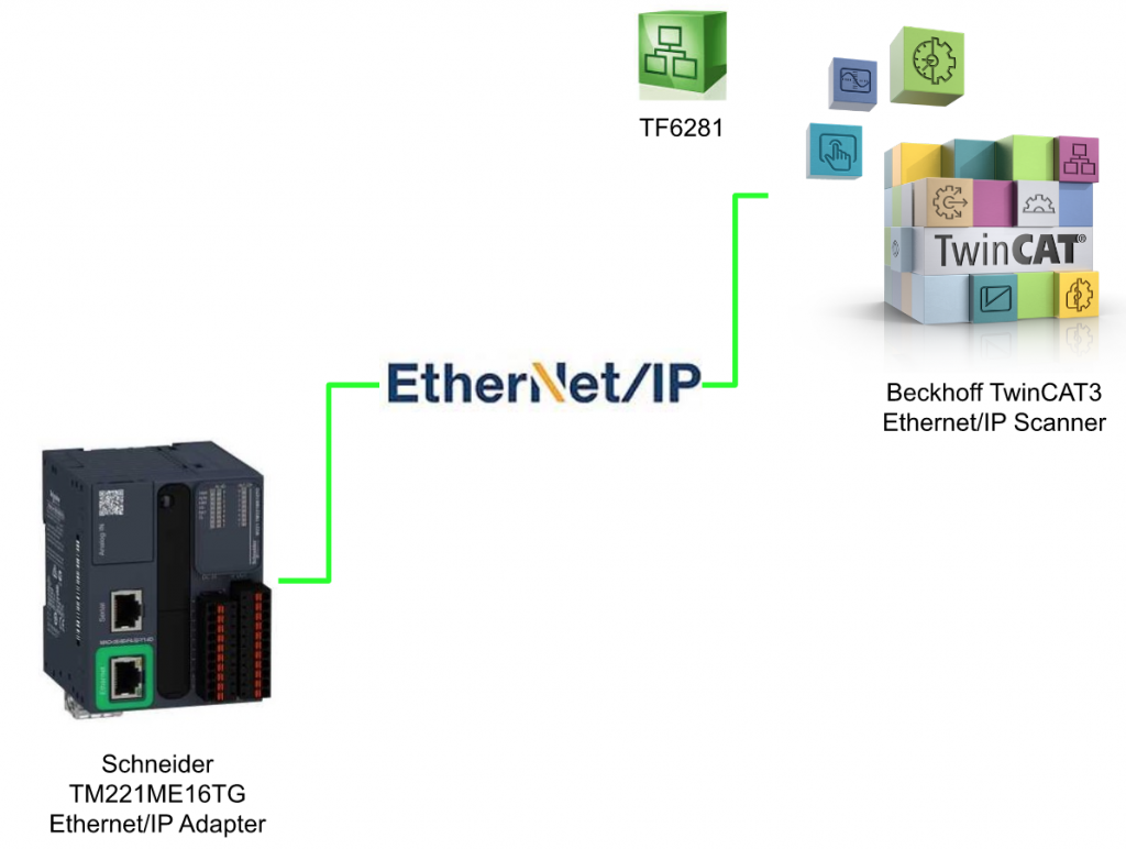
In this Tutorial I will show you how to configure a Ethernet/IP network with TwinCAT3 and Schneider TM221 CPU.Let’s start!
Version
This is my EcoStruxure Machine Expert – Basic Version.

Thanks!
Because of Beckhoff Japan and mana Design works that lend the devices to me – I can create this post.
Beckhoff Japan
IPC6920-005 was lent by Beckhoff Japan, a Japanese subsidiary of Beckhoff. Founded in 1980, Beckhoff Automation is a German company at the forefront of the introduction of open automation systems based on PC-based control technology.
Beckhoff Japan Corporation Beckhoff Automation Co., Ltd. established its head office in Yokohama in 2011 and the Nagoya office in 2017.

Here is the Home page of Beckhoff Japan.
https://www.beckhoff.com/ja-jp/
Mana Design Works
This article is provided also from Mana Design Works. The content of this blog itself is Schneider, but Mana Design Works is an official solution partner of Siemens ,headquartered in Osaka, Japan.Mana Design works can always make optimal proposals for Siemens CPUs, HMIs, drives, motion controllers, and SCADA to domestic manufacturers.

Please get more information from their home page:
Configuration
Schneider TM221ME16TG Side
ETH Set-up
Click the ETH1 to configure the Ethernet Interface.

Select “Fixed IP address” in the Ethernet field and enter the IP address.
Do not forget to check the “EtherNet/IP protocol enabled” checkbox to enable the Ethernet/IP adapter feature.

Ethernet/IP Adapter Set-up
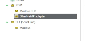
Click the EtherNet/IP adapter object to configure the Ethernet/IP Adapter.
Check the “Enabled” checkbox inside the Parameters Field.

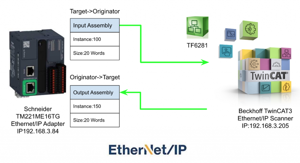
The default setting is used in this tutorial.
Output=Instance 100,20 Words
Input=Instance 150,20 Words

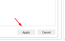
Click “Apply” to save the setting.
Program
Define
Let’s define the variables for Ethernet/IP Adapter.
Input
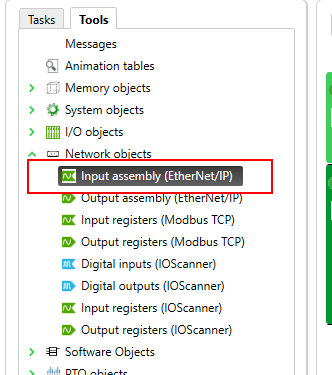
Go to Tools>Network objects>and click the Input assembly(Ethernet/IP).
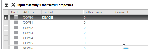
Enter the Symbol name “DEVICES1 ”to define the absolute memory address %QWE0.
Output
Go to Tools>Network objects and click the Output assembly(Ethernet/IP).

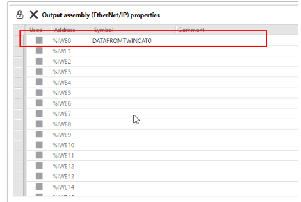
Define the Adsolute memory Address %IWE0 with Symbol name “DATAFROMTWINCAT0”.
And also define the Adsolute memory Address %IWE19 with Symbol name “DATAFROMTWINCAT19”.

Code
Go to Task>Master Task>and click the “1-New Pou” to create the new program.

Rung0-Move Constant Value
In this Rung, a constant value is output to TwinCAT3.
Click the Operation Block.
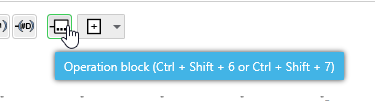
Drop the Operation Block to Rung 0 and click it.

Operation Block is inserted in Rung0.
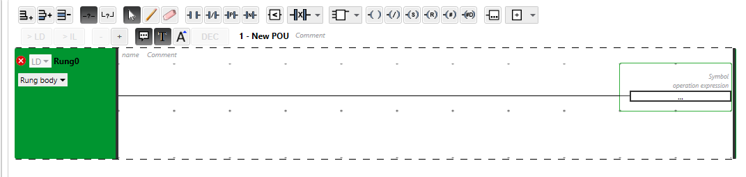
Now we can click the “Operation expression” Field in the Operation Block.

Enter %QWE0:=1234 in the Operation expressions field. Now Value 1234 will write to %QWE0, and %QWE0 is DEVICES1.

Rung 1-Increase itself
In Rung1, a self-increment program is operated. insert the operation block in Rung1 and Enter “%QWE19:=%QWE19+1” in the operation expression field.

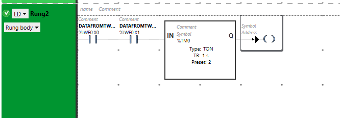
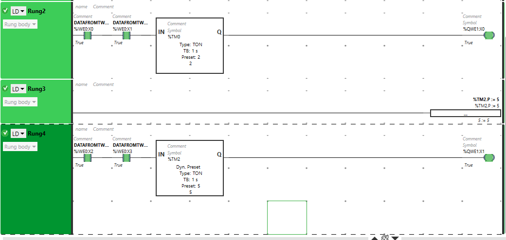
Rung2-Timer with Constant setpoint
In Rung2, A Timer with Constant setpoint is operated.Right Click the Rung1> Add Rung.

We will configure the timer Trigger condition first. select the Contact and Drop into Rung2.

NO Contact is inserted in Rung2.
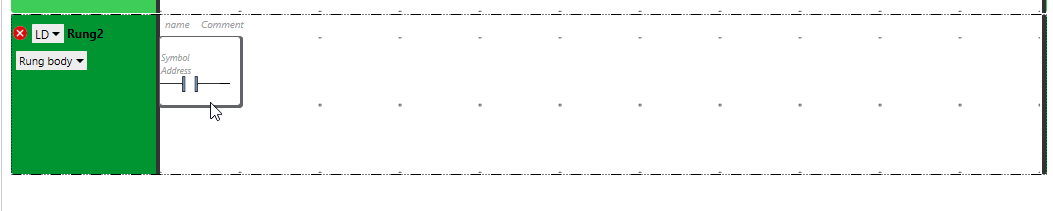
Click the “Symbol” field and enter the Devices for this NO Contact.
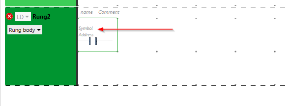
The data from TwinCAT3 is used here, so “DATAFROMTWINCAT0:X0” is entered in the symbol Field – it means the NO contact is accessing the first bit in the DATAFROMTWINCAT0 variable.
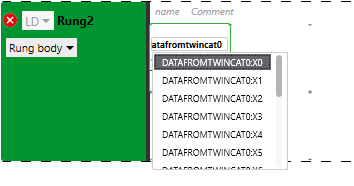
One more NO Contact is inserted and enter “DATAFROMTWINCAT0:X1” in the Symbol field – it means the NO contact is accessing the second bit in the DATAFROMTWINCAT1 variable.

Open the Function Block selection menu>and click the timer.
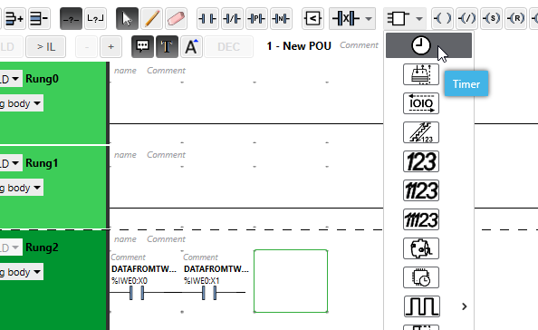
Drop the timer block at the end of the NO Contact.

Timer is inserted.
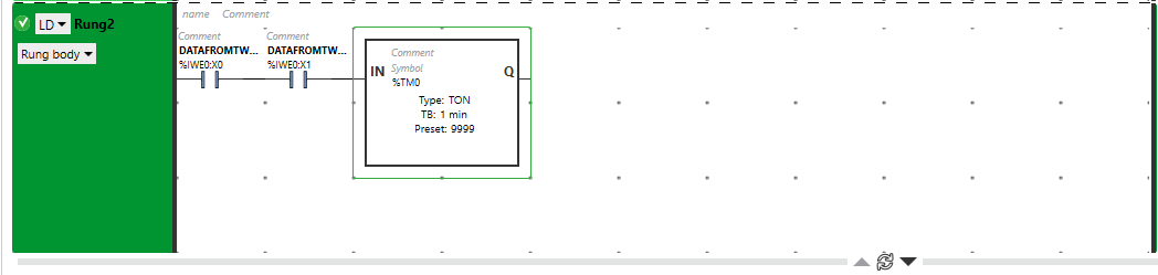
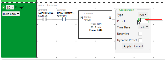
we can directly configure the Timer by clicking the Timer. A Configuration Popup is shown.
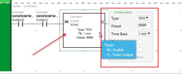
Enter 2 in the Preset Field.
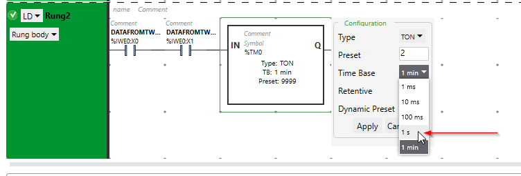
Select 1s in the time base drop list, the timer is configured as a 2s delay on timer now.
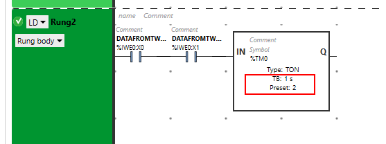
Press Apply to save the setting.

Timer setting is done!
Now we can connect the output signal of timer.Select the Coil icon in the toolbar and drop in the “Q” of the timer.
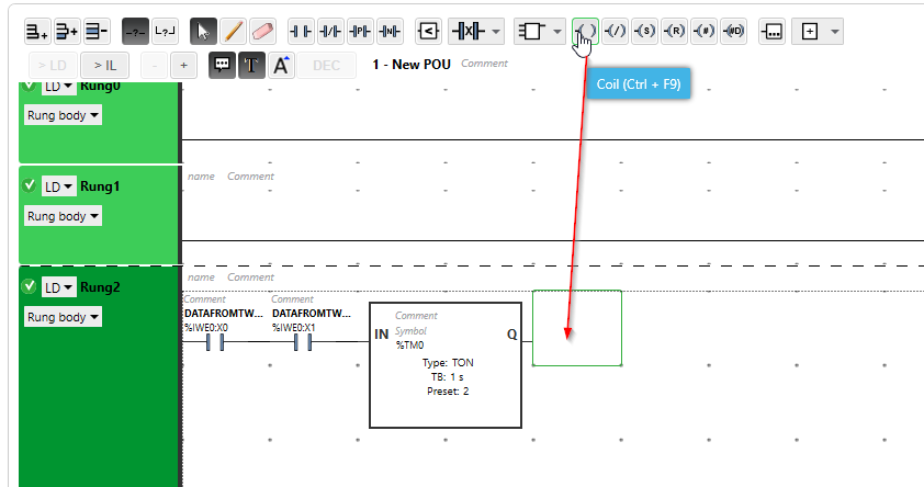
Coil is inserted.
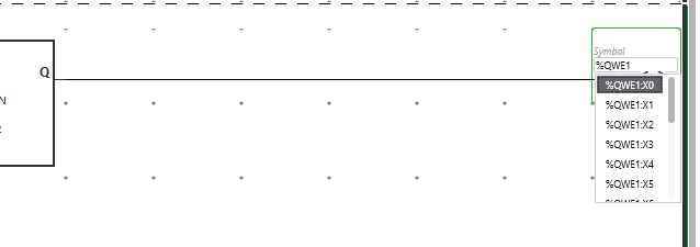
Click the Address Field.
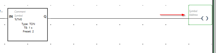
Enter QWE1:X0 in the Address Field. Now QWE1:X0 will be true while the delay on the timer is triggered, and the 0bit of 1st word that is sent to TwinCAT will be changed to “True”.
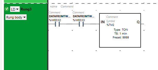
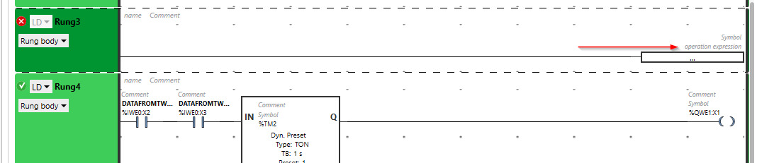
Rung3-Timer with Dynamic Setpoint
In the Rung3, a Dynamic Setpoint timer is configured.Following the process is the same as Rung2 and change the timer number by clicking the %TM1 field.
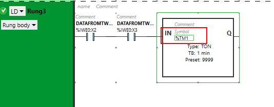
Just enter another Timer number. In this case, %TM2 is used.
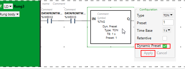
Now we can configure this Delay on Timer.Click %TM2 and Check the “Dynamic Preset” Checkbox>Press Apply to save the setting.
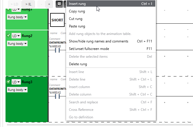
Rung-Add Timer Dynamic Setpoint
Select Rung3 and Right Click>Insert Rung.
Insert an operation block in this Rung3.
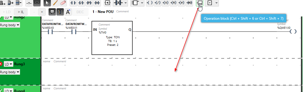
Click the operaton expression Field.
Enter “%TM2.P:=5”, The Setpoint of %TM2 is changed to 5s now.

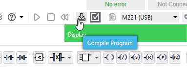
Compile
Press Compile program to compile the project.
Download
Open the Commissioning Tab>Login.
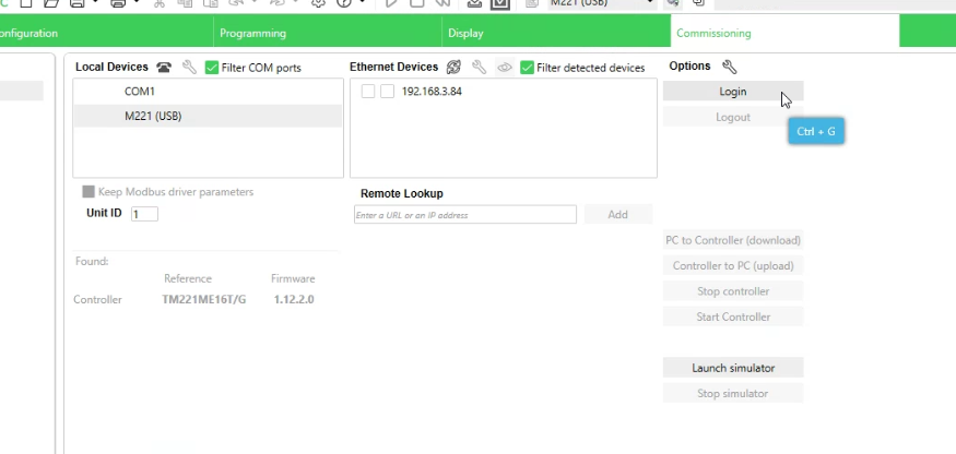
Click the PC to Controller (download) button to download the project inside the CPU.
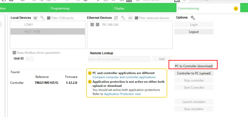
Press OK to confirm the overwrite operation.

Start Controller
Press “Start Controller” to shift the CPU status to Run.

OK. The Schneider side is done!

TwinCAT Side
Add Ethernet/IP Scanner
Go to I/O>Device>Right Click >Add New Item.
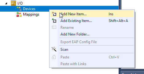
Choose EtherNet/IP Scanner>Ok.

Select the interface that is connected with Schneider TM221 CPU>OK.
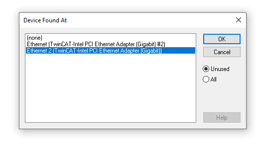
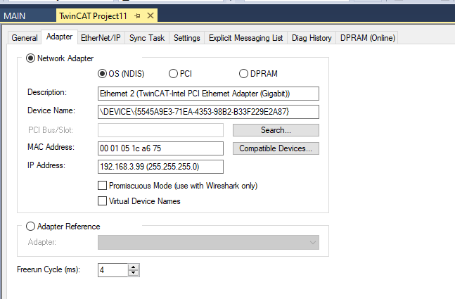
Please double check the the IP address setting in the Adapter Tab.
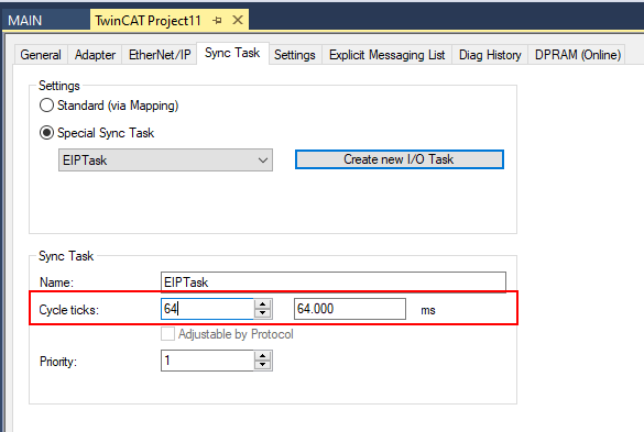
Configure the Task
Open the Sync Task>Select Special Sync task>Create new I/O Task to create a new task for the Ethernet/IP scanner.
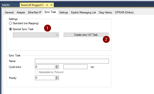
Enter the Task and OK.

Change the Cycle ticks for your Ethernet/IP Cycle.
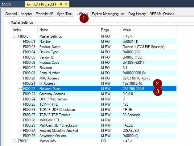
Set the Virtual IP
Open the Settings Tab and Set the IP address of the Ethernet/IP Scanner in TwinCAT. Please do not duplicate the ip address with your Ethernet Interface.
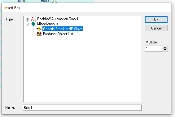
Add Generic EtherNet/IP Slave
Right Click the Ethernet/IP Scanner that you created in the last Step>Add New Item.
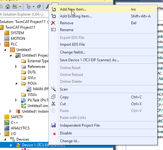
Choose Generic EtherNet/IP Slave and Ok.
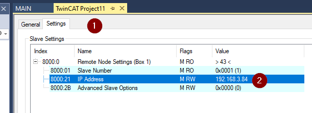
Configure the IP
Click the Adapter that you created.
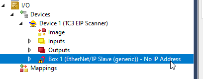
Open the Setting Tab>Set the IP address as the same as TM221 CPU in the 8000:21 field.
Append IO Connection
Now we can Append the IO Connection Point.Right click the Box>Append IO Connection>Default(without eds).

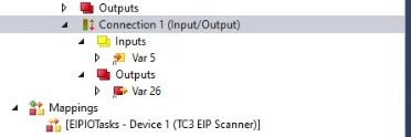
Connection1 is created.

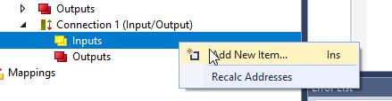
Add Inputs
Connection1>Inputs>Right Click and Add New Item.
The insert Variable screen is shown.
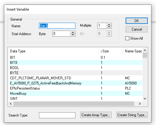
Choose WORD as the Data type and press the “Create Array Type” button.
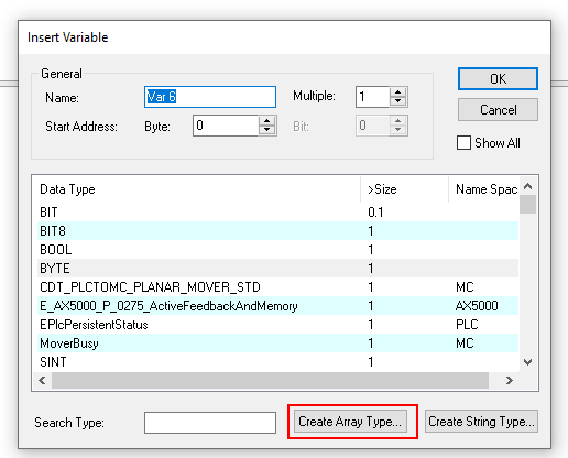
Check the “0” Checkbox and enter 0..19 to define an array with 20 elements>ok.

Press Ok to finish the process.
Add Outputs
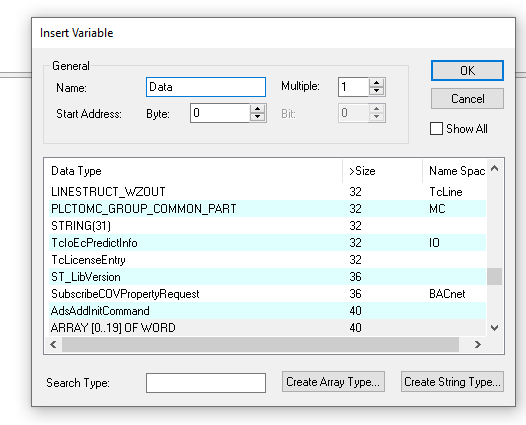
Go to Output>Right Click and Add New Item.

Now we can directly choose ARRAY[0..19] as the data type.
Choose ARRAY[0..19]OF WORD and press OK to confirm it.

Configure the Connections
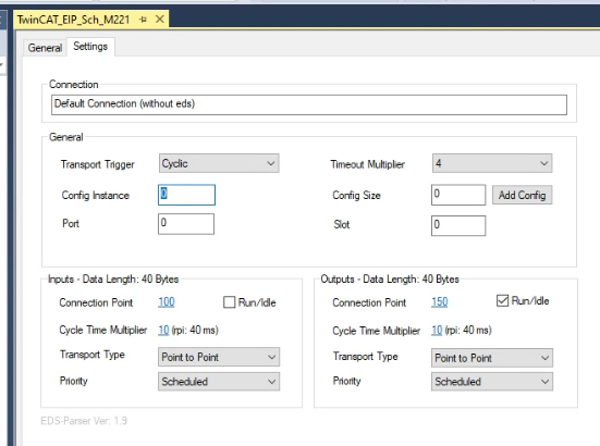
Click the Connection1 to configure the connection setting with Adapter(Schneider TM221).
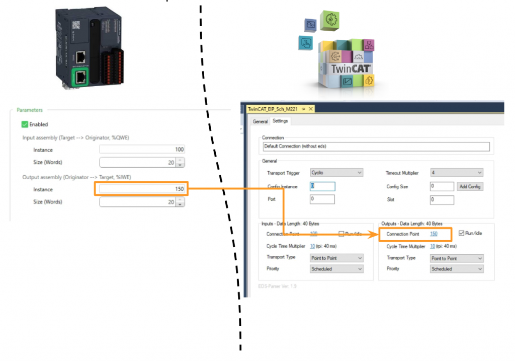
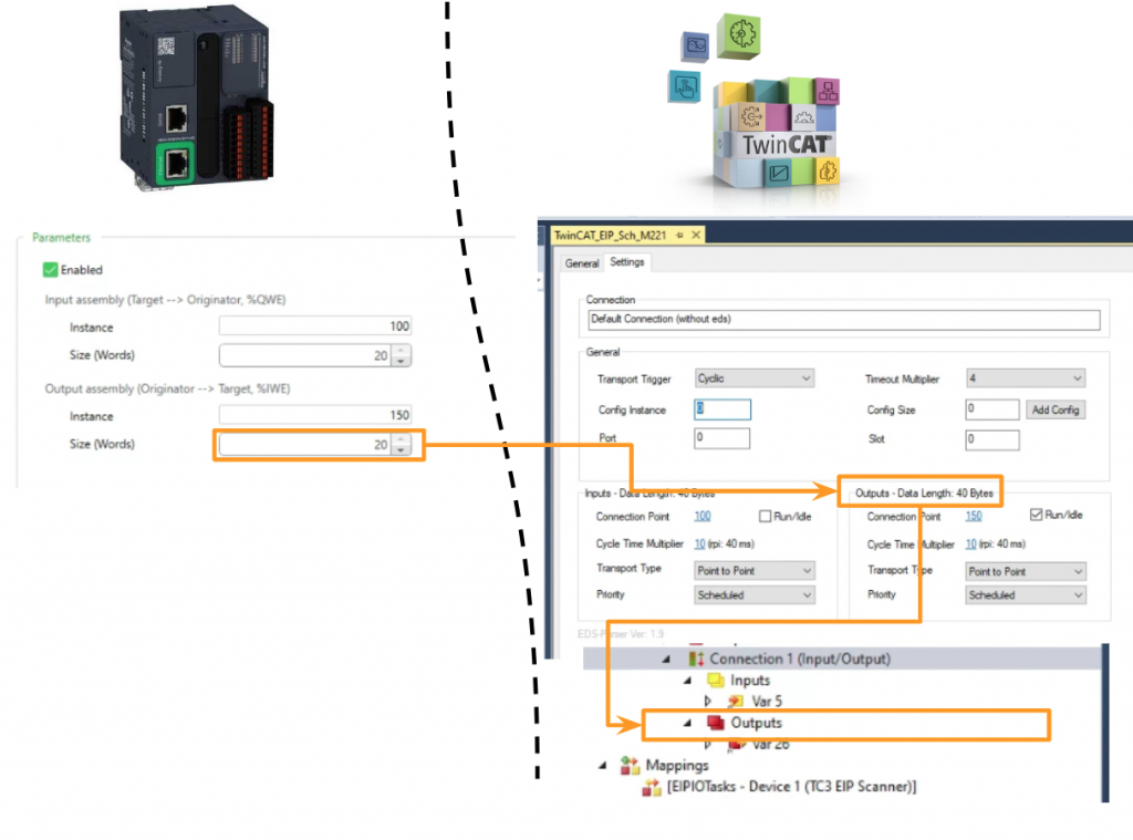
Input Connection =100,Output Connection Port=150.
And change the Transport Type as Point to Point.
Add PLC
Finally we can create some simple programs to verify the connections.
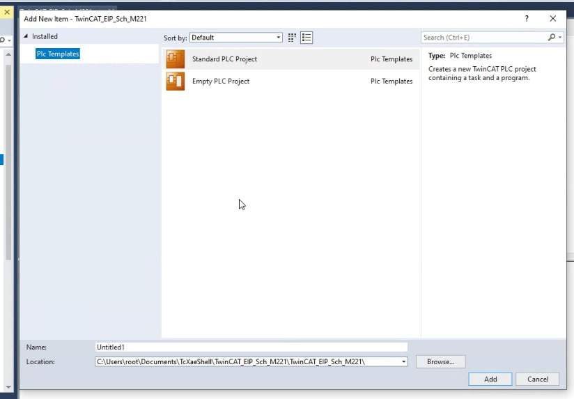
Go to PLC>Right Click> Add New Item.

Choose Standard PLC Project>Add.
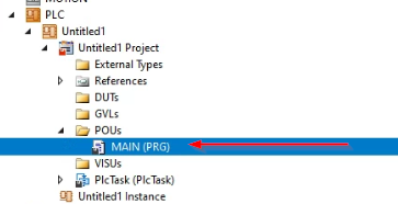
MAIN
Go to POUs and Click MAIN.
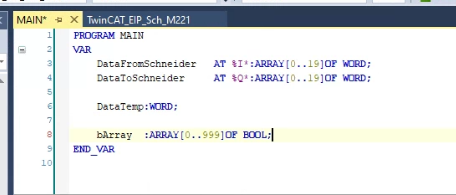
VAR
Define the Process IO variable that Used to Link with Schneider TM221 CPU Ethernet/IP Adapter I/O Data.
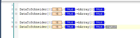
Program
Here is the program.
Build
Go to Build>Build Solution to compile your project.

Link to INPUT
Link the User program variables with Schneider TM221 CPU’s input variables.
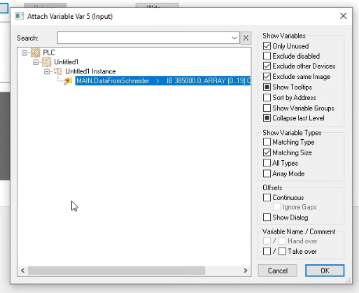
Go to Box1>Connection1>Input>Right Click the Variable and Change Link.
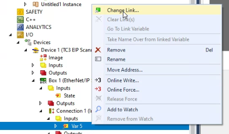
Choose the variable with %I* inside your User program.
Link to OUTPUT
Link the User program variables with Schneider TM221 CPU’s Output variables.
Go to Box1>Connection1>Output>Right Click the Variable and Change Link.

Choose the variable with %Q* inside your User program.

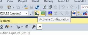
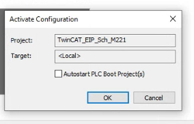
Activate
Press Activate Configuration to Download the Hardware Configuration in your Runtime.
Ok.
Restart your Runtime.
Login
Press Login to download the User Program.

Yes.

Start
Finally, press the start button to change the runtime to Run mode.
Summary
In this Part, The main points are summarized.
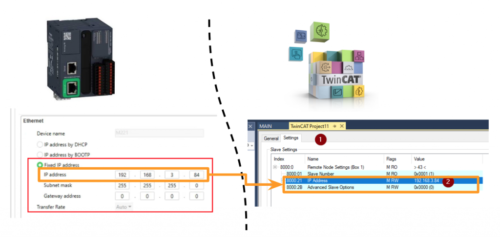
Ip Address
Please match the IP address in the TwinCAT Ethernet/IP Adapter 8000:21 Field.
Input Assembly(T–>O) Instance
For the Instance number of T–>O, please match the setting of “Input Connection Port” in the TwinCAT Ethernet/IP Adapter side.
Input assembly(T–>O) Size
For the T–>O Data size,please match the setting of “InputData” in the TwinCAT Ethernet/IP Adapter side.
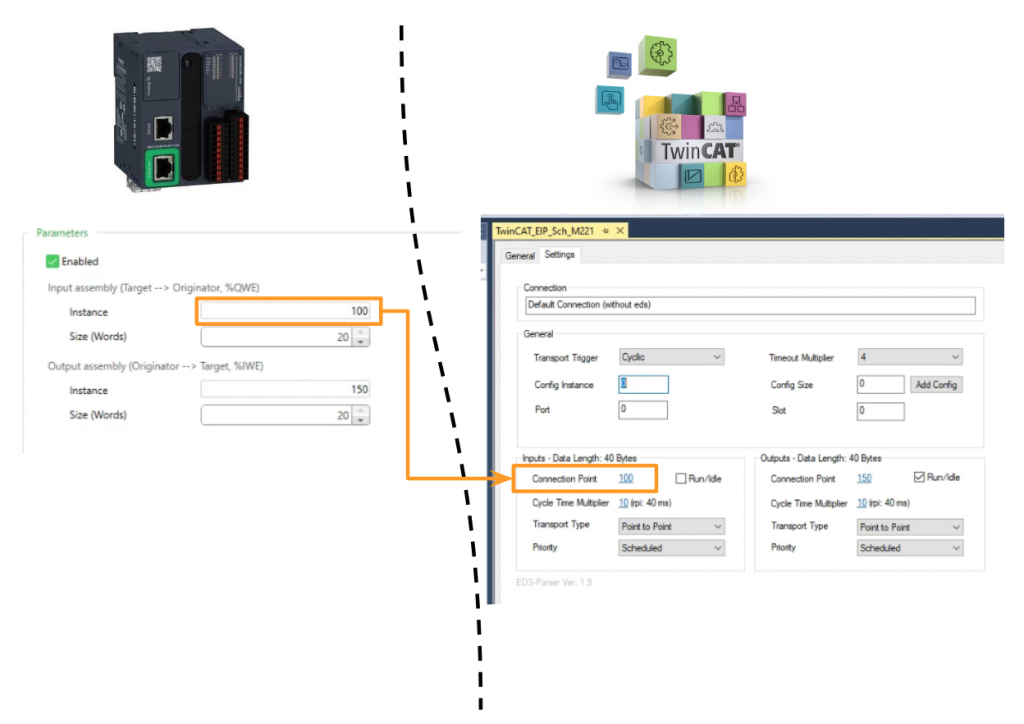
Output Assembly(O–>T) Instance
For the Instance number of T–>O, please match the setting of “Output Connection Port” in the TwinCAT Ethernet/IP Adapter side.
Input assembly(O–>T) Size
For the O–>T Data size,please match the setting of “OutputData” in the TwinCAT Ethernet/IP Adapter side.
Result
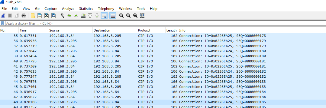
Now we can see the CIP I/O Packages by using wireshark.
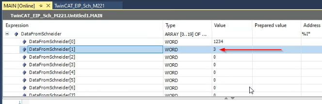
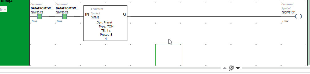
%IWE0:X2 and %IWE0:X3 are True from the TwinCAT side and Trigger the Timer.
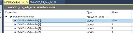
And also You can see the output data from Schneider Side in TwinCAT.

Now we can Turn on the Bit0,1,2,3 in the TwinCAT side Output.

In Schneider TM221, Timer is triggered and Q is ON.
And we can see the DataFromSchneider[1] is equal to 3 because Bit0, Bit1 – the Output of Schneider TM221 CPU are true.