In this article we will run a Beckhoff TwinCAT3 and a servo system from Delta with EtherCAT. The article will be live-programmed with a combination of Interface, Properties, Methods, Function Block, Extends, etc. We will also show you how to create a simple Scope project from TwinCAT.
Let’s enjoy FA.
Reference Video
Beckhoff.Let’s play with Delta ASDA-A3 servo drive!
Reference Link
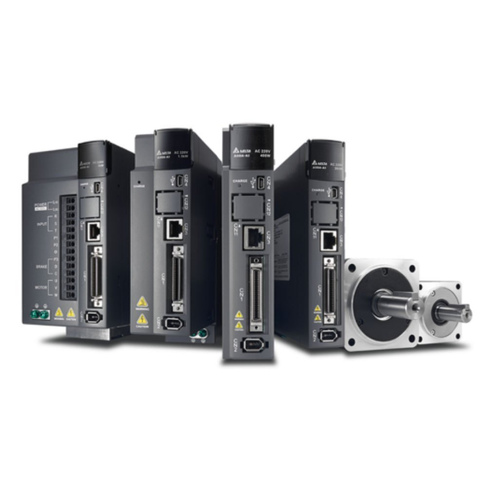
Servo ASDA-A3?
The Servo used in this project will be Delta’s ASDA-A3 series Servo.
Layout
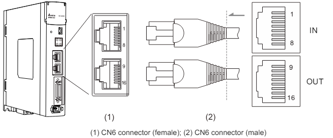
EtherCAT Mode
The ASDA-A3 servo system can use EtherCAT mode, and the pin assignments of the two EtherCAT connectors (CN6) are identical.
Note that the IN connector can be connected to the controller (master) or the previous servo drive for receiving, and the OUT connector can only be connected to the next servo drive for output. Incorrect connection will result in loss of communication.
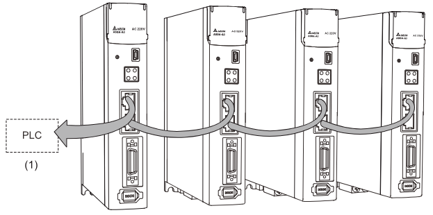
Connection Example
The figure below shows an example of connecting multiple ASDA-A3 servo systems on an EtherCAT network.
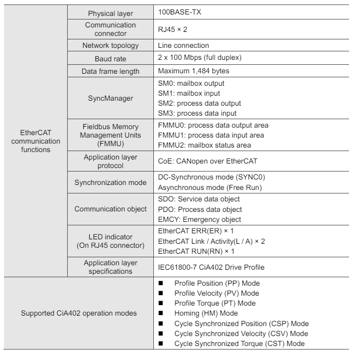
Specification
This is the EtherCAT version of the ASDA-A3 servo system.
Architecture
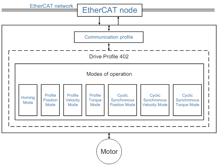
The EtherCAT architecture of the servo drive is as follows
- Communication profile: This protocol includes communication objects (PDO, SDO, SYNC, and emergency objects) and the associated communication object dictionary.
- DS402: Device profile for drive and motion control, defining the behavior of each motion mode and the object parameter settings required to execute it.
Synchronous mode
Delta servo drives support two synchronous modes: Free Mode and DC-Synchronous mode.
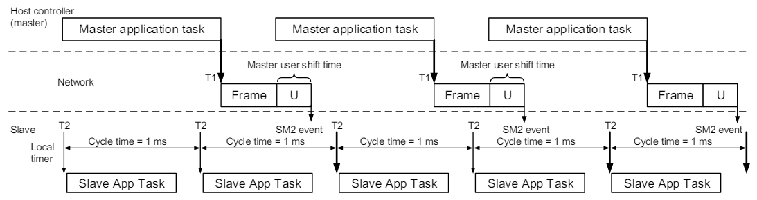
Free Run mode (Asynchronous)
In Free Run mode, the master and slave stations operate asynchronously. Each station has a separate clock that calculates time, and the master and slave clocks are not synchronized. The transmission of commands and feedback between master and slave is based on sequential order rather than precise time synchronization. For example, the master sends a PDO at time T1 and the slave receives the PDO at T2 after the SM2 event.
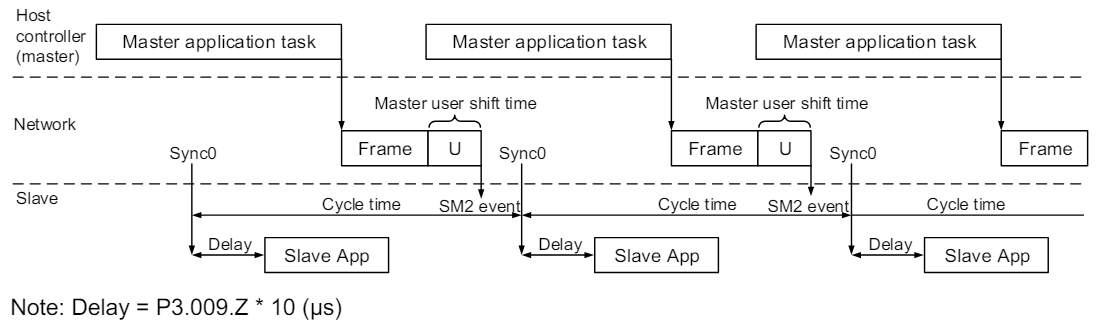
DC-Synchronous mode (SYNC0 synchronization)
There will be precise time synchronization between the master and slave stations so that the master will periodically run the control program and send PDO packets at fixed times according to the synchronization clock. The master sends commands to the slave and receives feedback from the slave, which in turn receives and updates the PDO data at regular intervals according to the synchronization clock.
PDO mapping configuration
PDO mapping objects are allocated in the object dictionary from index OD 1600 to OD 1603 for RxPDO and from index OD 1A00 to OD 1A03 for TxPDO.
Each group of RxPDO and TxPDO can support PDO data updates for up to 8 sets of 32-bit objects.
Default PDO mapping configuration
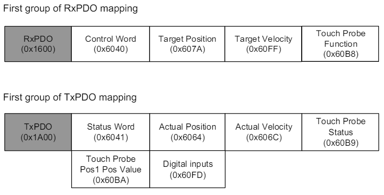
The table below shows the default PDO mapping settings of the EtherCAT servo drives for data exchange. This is also defined in the XML file of the EtherCAT slave and the PDO mapping settings can be changed on request.
In Delta ASDA-x3-E rev0.03.xml, the first through fourth groups of PDO configurations are as follows
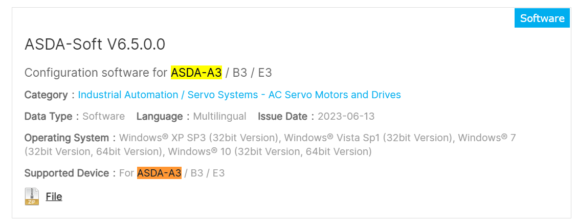
ASDA-Software Tools
Download ASDA-Soft at the link below for commissioning with Delta’s Servo.
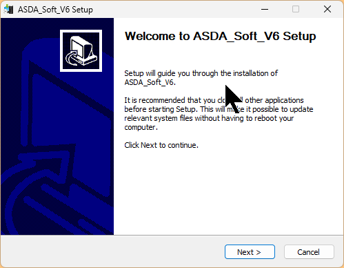
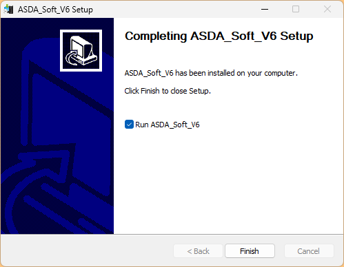
Start the installation EXE and proceed with Next>.
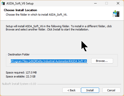
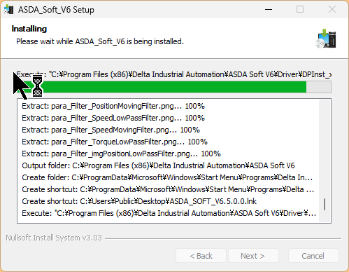
Set the installation location of the tool and proceed with Install.
Just a second..
The USB Driver installation screen will appear, and click Install to install the Driver that communicates with the Servo Drive.
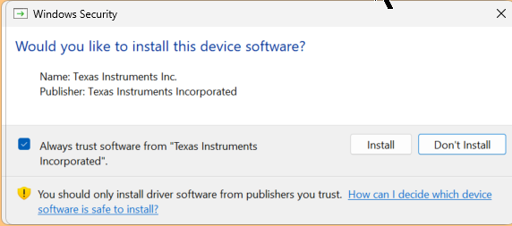
Done!
Implementation1-Commissioning
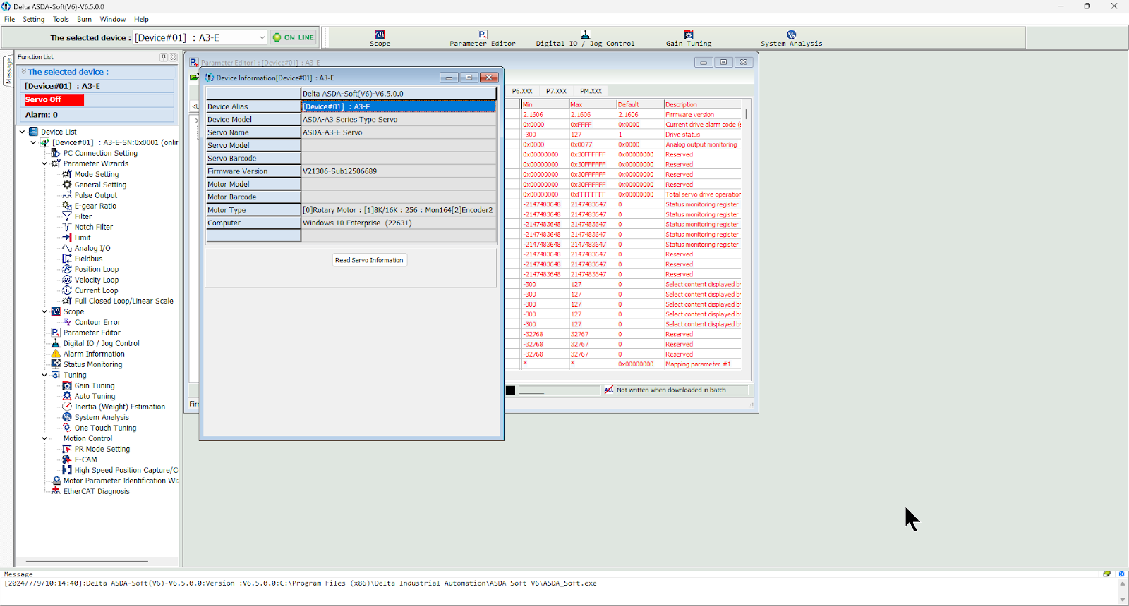
Launch the ASDA-Software tool.
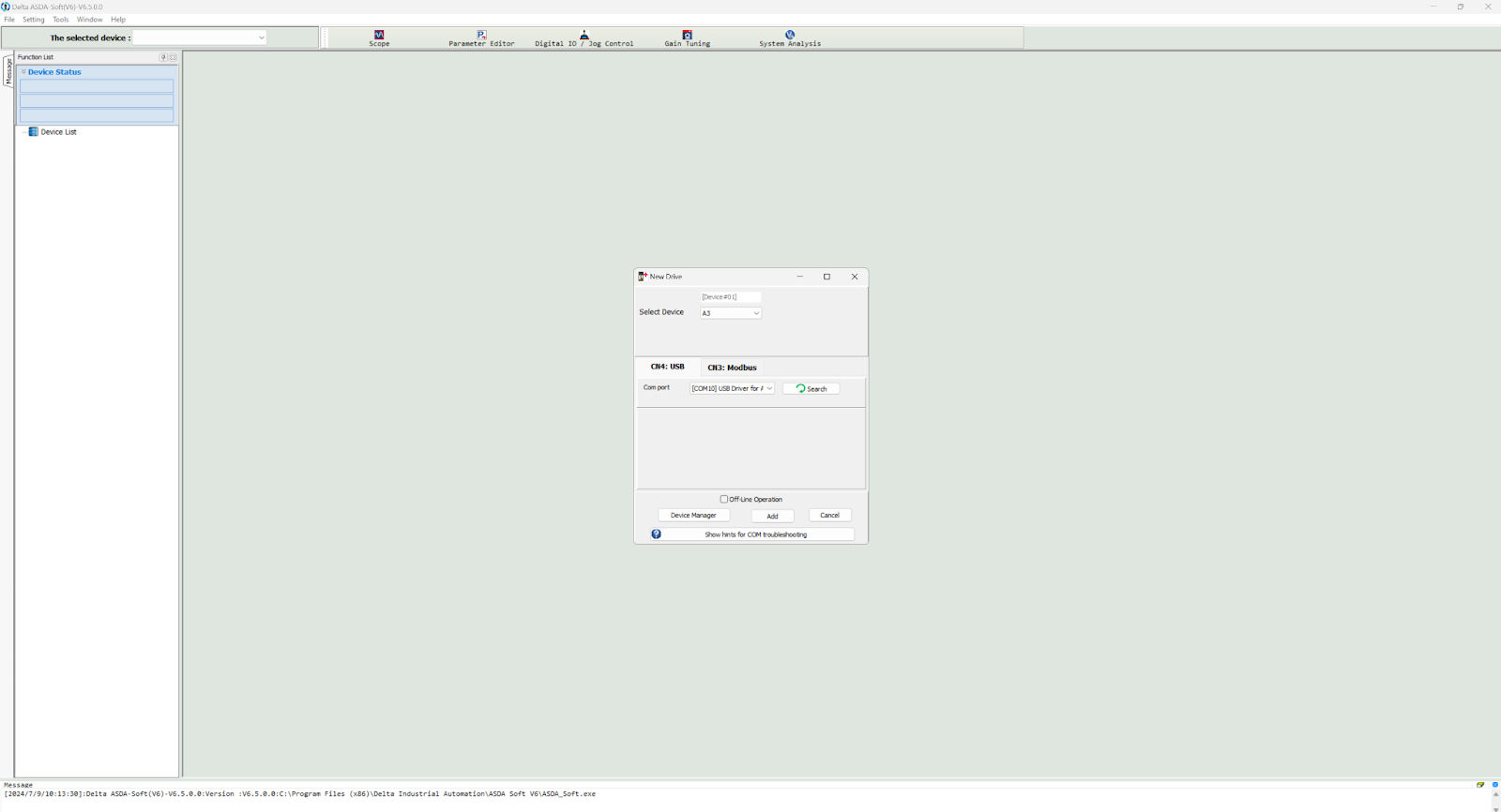
Connect to the Drive
Set the USB port to connect the PC and Servo in Com port, and connect Servo Drive in Add port.
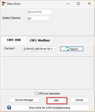
Done!
Panel Operation
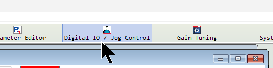
Click Digital IO/ Jog Control.
This is Servo’s DIO screen.
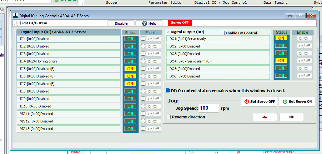
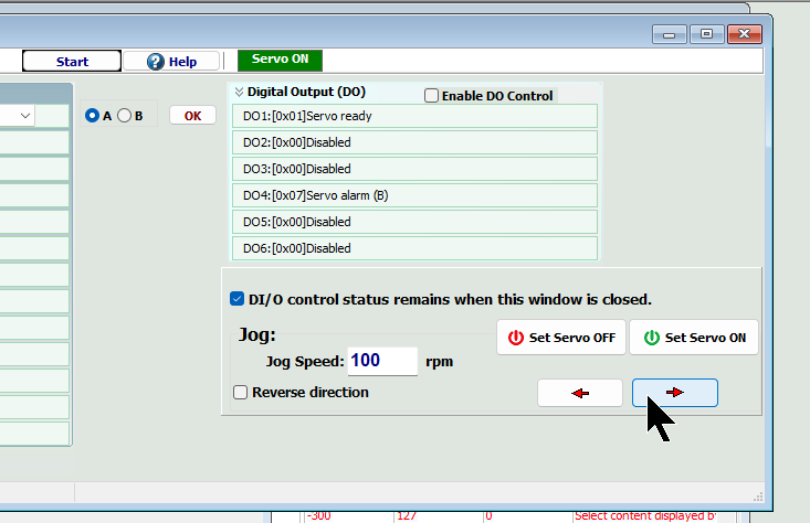
Click Set Servo ON to issue Servo ON command.
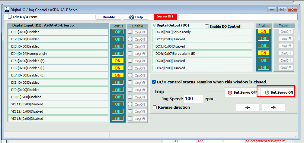
Next, press the arrow to enable Servo’s JOG operation.
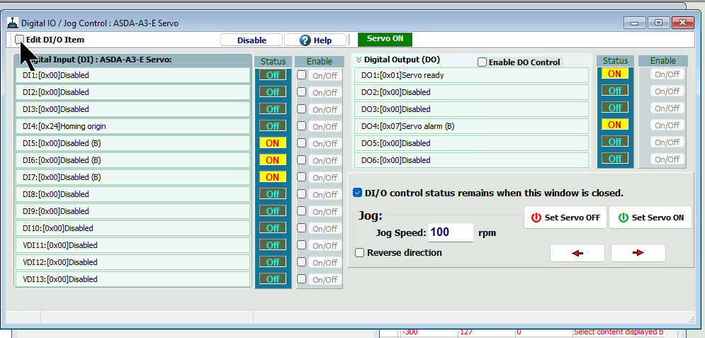
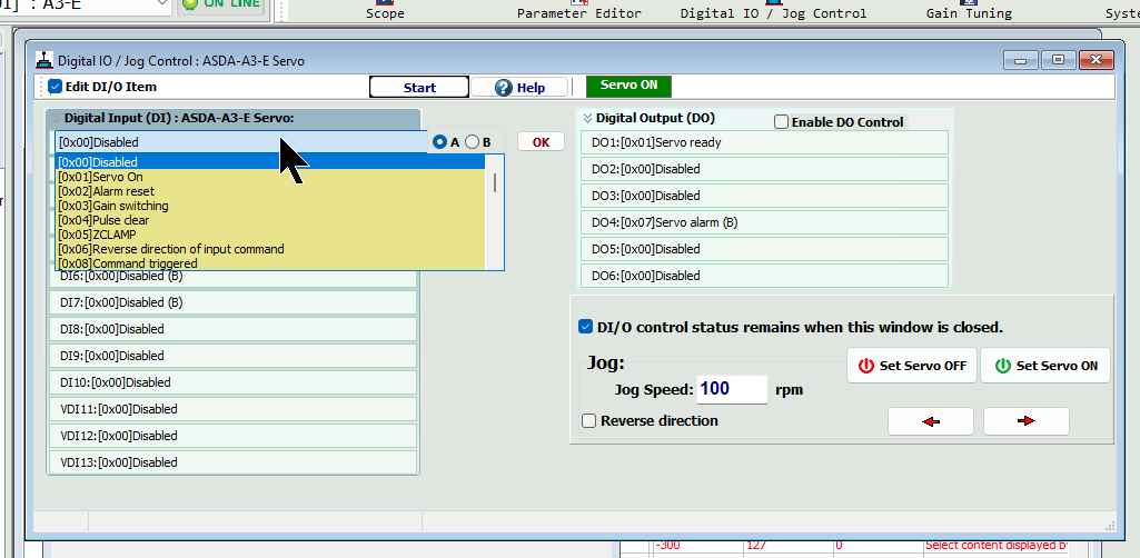
If you want to change the meaning of DIO, put CheckBox in the Edit DI/O Item.
Then you can change the assignment from drop-list to each DIO.
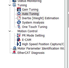
Auto Tuning
Next, click Tuning>Auto Tuning for Auto Tuning.
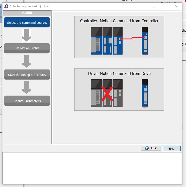
Since we are going to do it alone this time, let’s click on Motion Command from Drive.
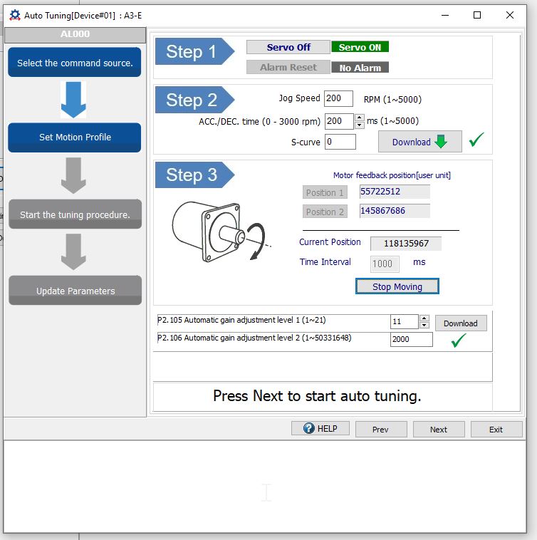
Next, the Motion Profile screen appears.
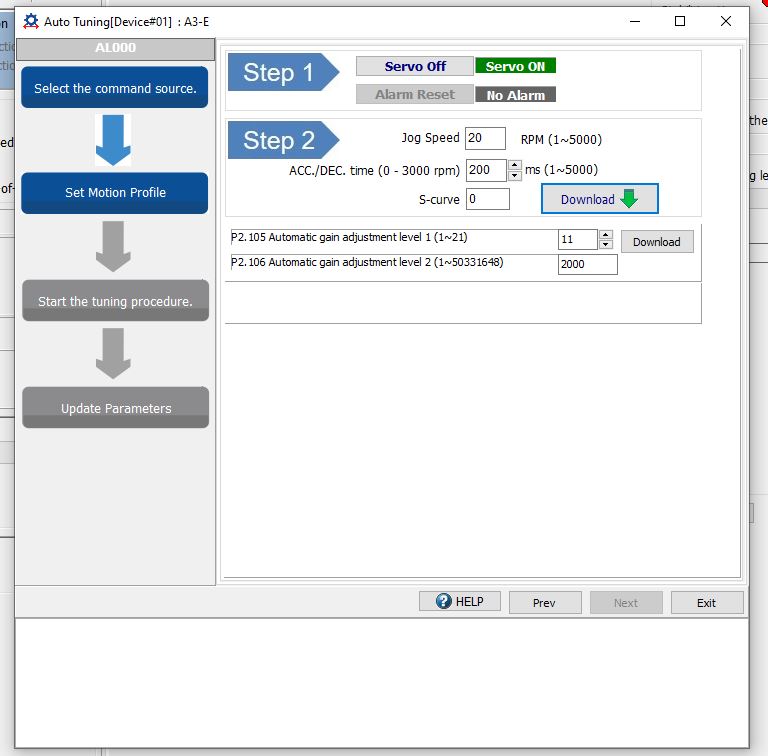
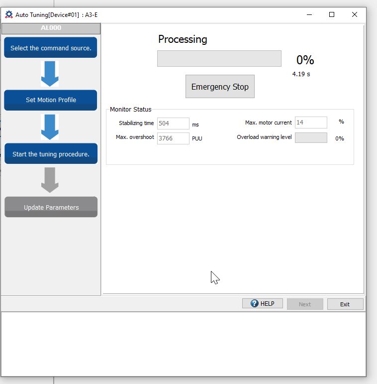
Turn Servo ON, and record Jog Speed, acceleration/deceleration, and then turn Motor and click Position1/Position2. Finally, click Next.
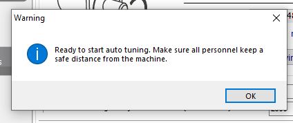
Proceed with Ok.
Just a second..
Done!
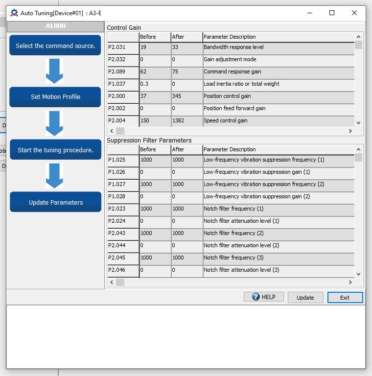
Finally, click the Update button to update the parameters.
Implementation2
Delta Drive Side
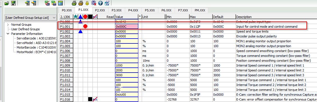
Set P1.001 to 0x000C in the parameters. This is the setting for EtherCAT communication.
TwinCAT Side
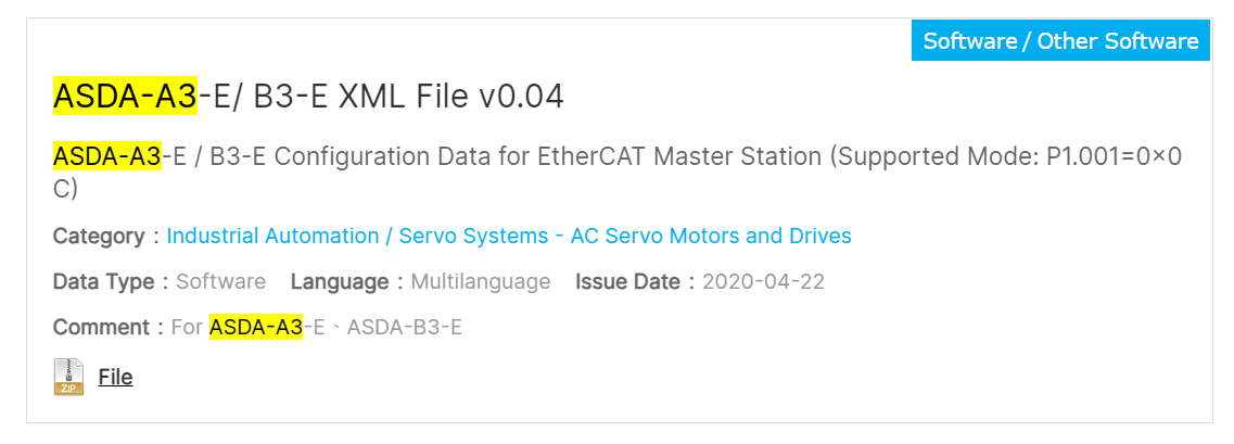
Download ESI File
Download Delta’s ESI File from the link below.
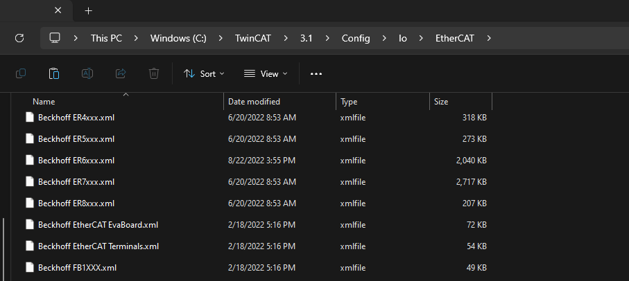
Install the ESI File
Store the ESI File TwinCAT/3.1/Config/io/EtherCAT that you downloaded earlier.
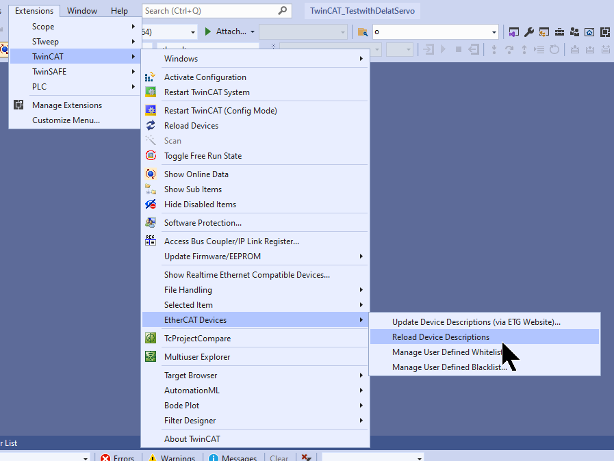
Next, restart TwinCAT or click on Extensions>TwinCAT Device>Reload Device Description to reload the ESI File.
Connect to TwinCAT Runtime
If TwinCAT Runtime is not local, you will need to set up a connection point and open SYSTEM.
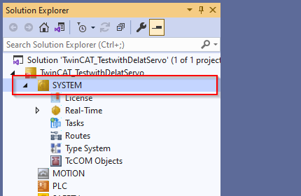
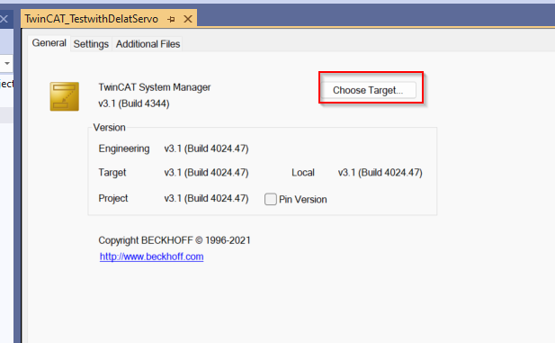
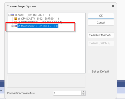
Click Choose Target.
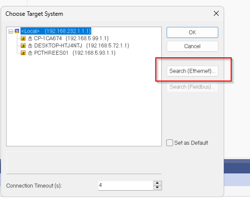
Click Search(Ethernet).
The Route Dialog screen will appear and you should enter the IP of the PC on which TwinCAT Runtime is installed. Then select the PC and the Runtime you wish to connect to.
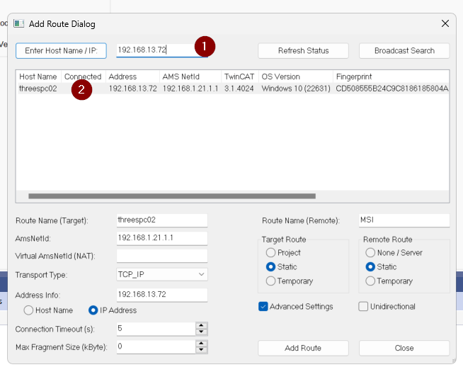
Click Add Route.
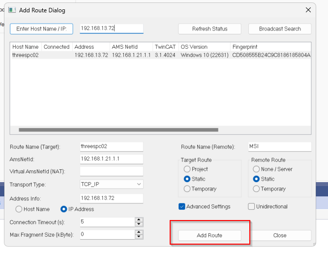
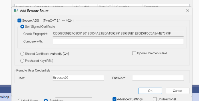
Enter the User Name and Passwowrd of the PC and proceed with OK.
Done!
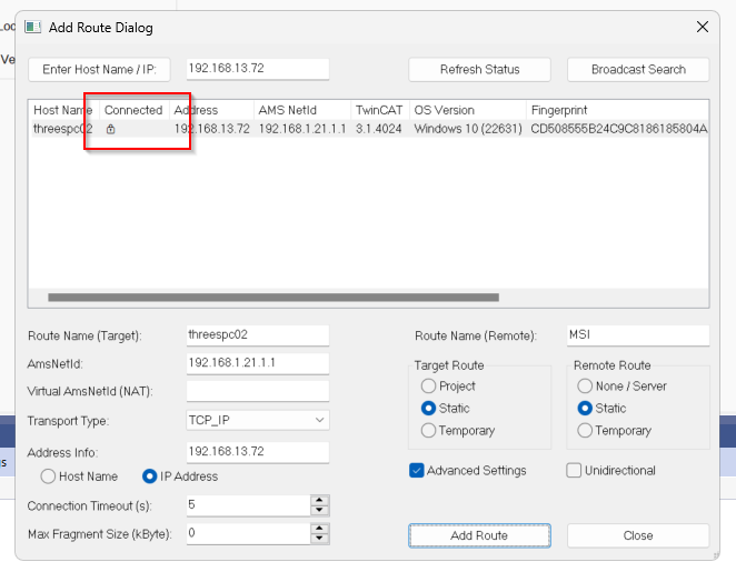
We can now also check the status of TwinCAT on another PC.
Configure EtherCAT Master
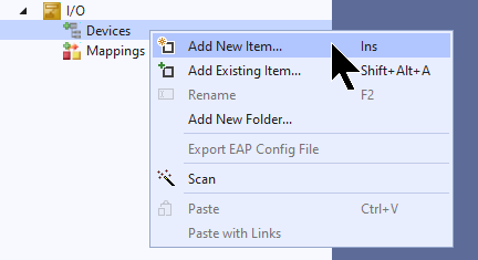
To add an EtherCAT Master, go to I/O>Devices>Add New Item.
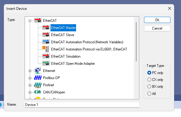
Select EtherCAT>EtherCAT Master and proceed with Ok.
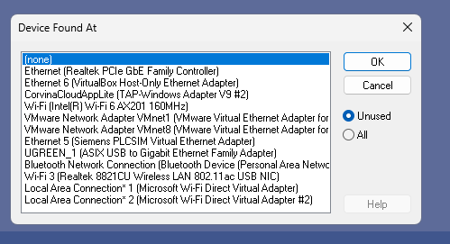
This is the screen for configuring the Ethernet Adapter you want to use as an EtherCAT Maseter, once you select None, proceed with Ok.
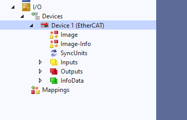
Done!EtherCAT Master has been added.
Configure the PCI Bus/Slot
Next, click on Compatible Devices to configure the Ethernet Adapter.
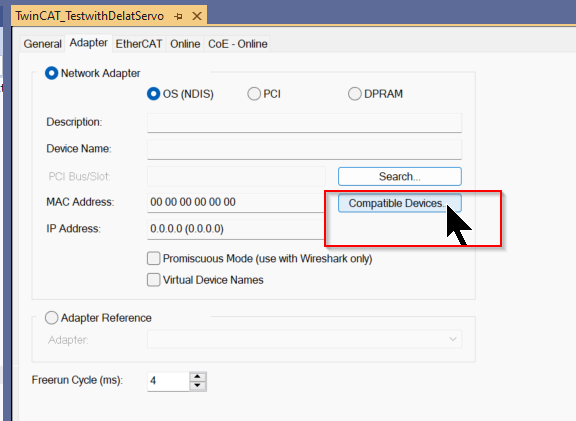
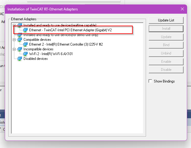
If the screen shown below appears on the corresponding TwinCAT XAE, you need to install the TwinCAT RT-ET Ethernet Adapters.
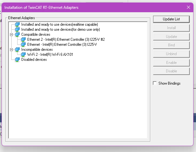
Select the Ethernet Adapter you wish to use as EtherCAT Master and click >Install.
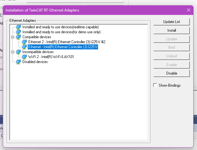
Proceed with Install.
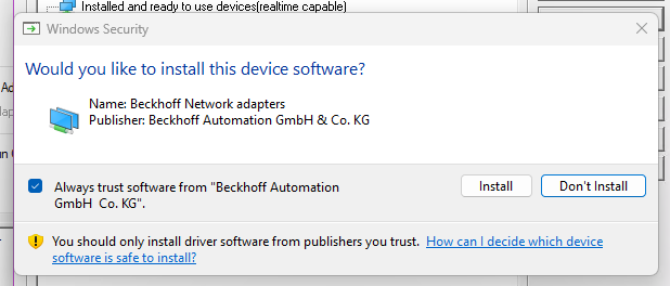
Done!
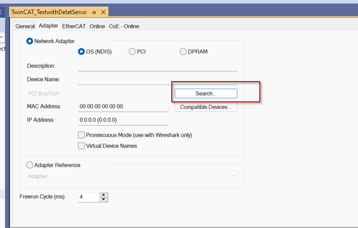
Next, click on the Search button.
You can now use the Ethernet RT Driver that you have just installed!
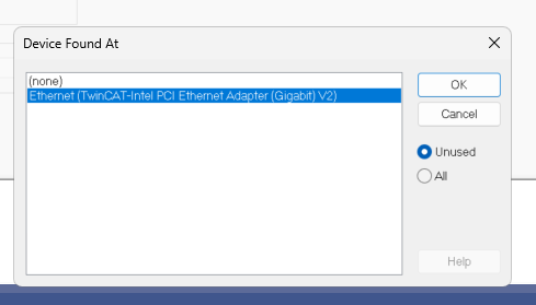
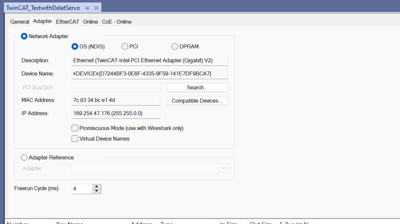
Done!
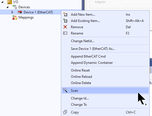
Scan Network
Use TwinCAT’s Auto Scan function to search for EtherCAT Slaves in the network.
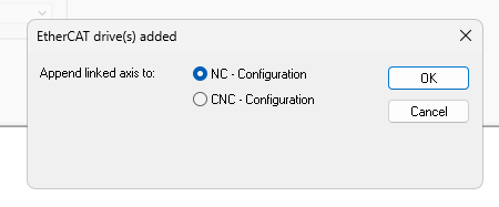
Servo of Delta is detected and you can select whether the corresponding axis is an NC axis or a CNC axis.
This time, select NC-Configuration and proceed with Ok.
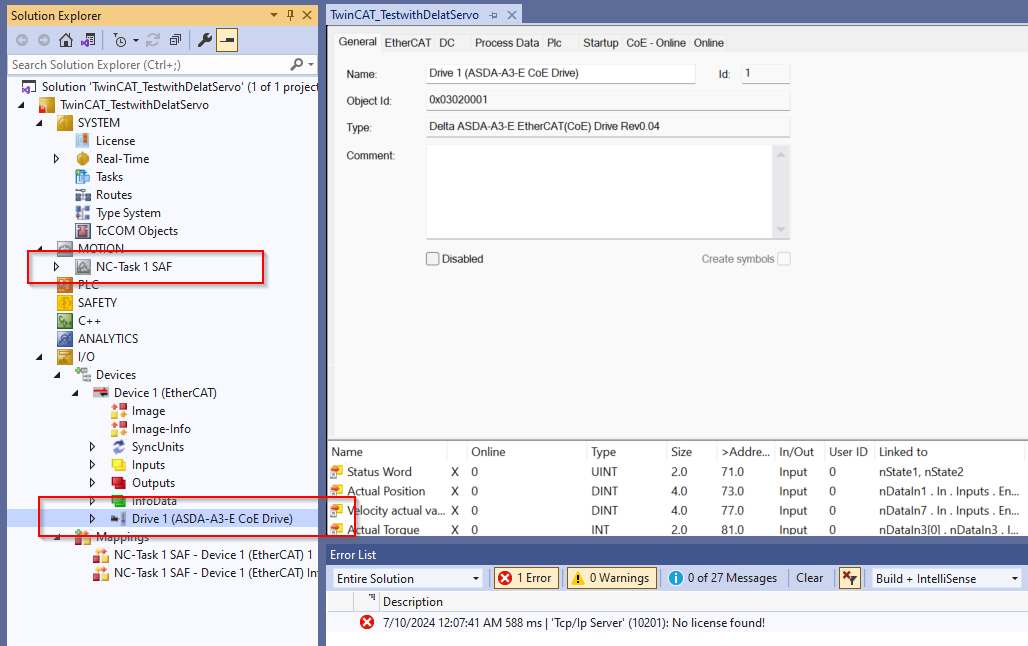
Done!It has also been added to Delta’s Servo Drive and NC axes.
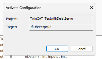
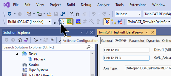
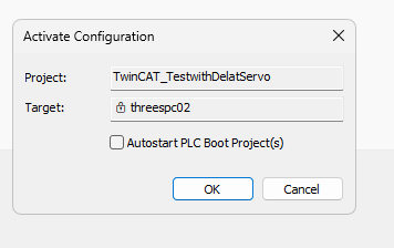
Activate Configuration
Next, click Active Configuration and Download the project once to Runtime.
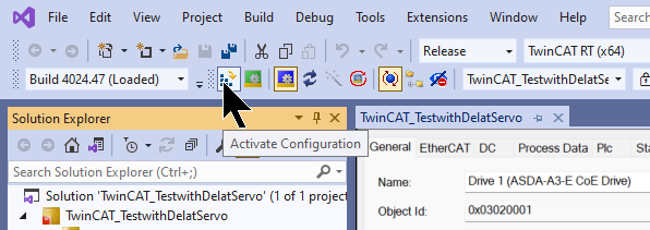
OK to proceed.
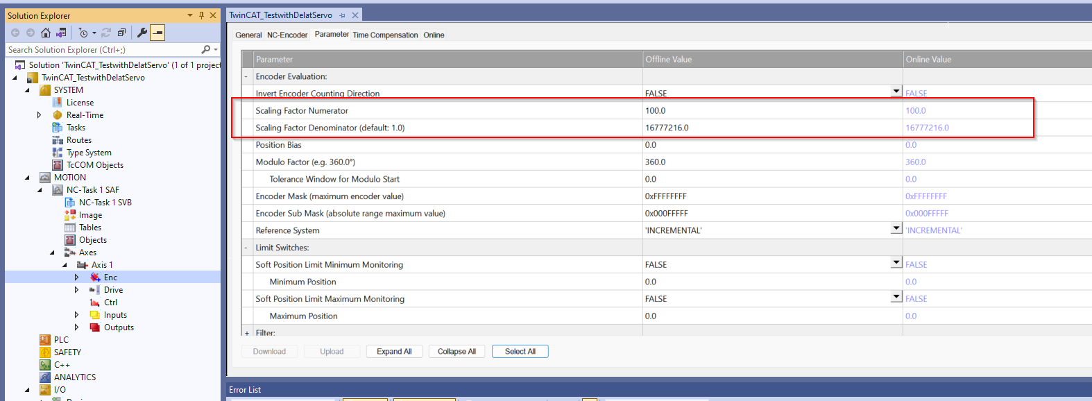
Enc Setting
Next, set the Scaling Factor on the Enc setting screen.
- Numerator:100
- Denominator: 16777216
As noted in Delta’s instruction manual, the ASDA-A3 has a 24-bit resolution and generates 16,777,216 pulses per motor revolution. Regardless of the encoder resolution (17-bit, 20-bit, or 22-bit), the E-Gear ratio is set according to the 24-bit resolution of the ASDA-A3 servo drive. There is also a parameter called E-Gear ratio, which, when set to 1, generates 16,777,216 pulses per motor revolution.
In other words, now at 16777216 pulses per (1 revolution), the Beckhoff NC Drive is recognized as 100 mm.
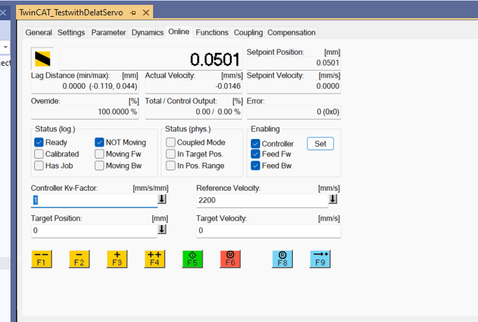
Commissioning with Panel
Finally, try to operate Servo Drive directly with Axis >Axis 1 >Online.
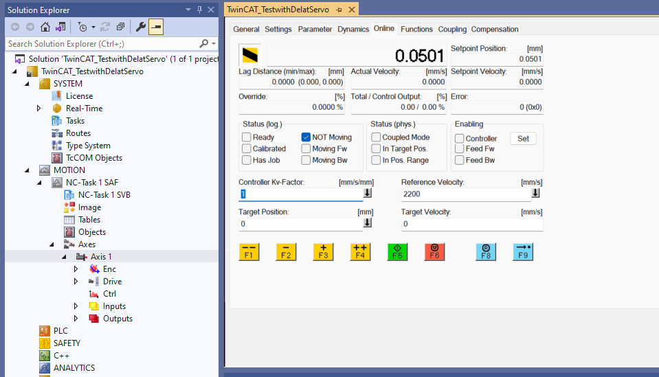
Click Set.
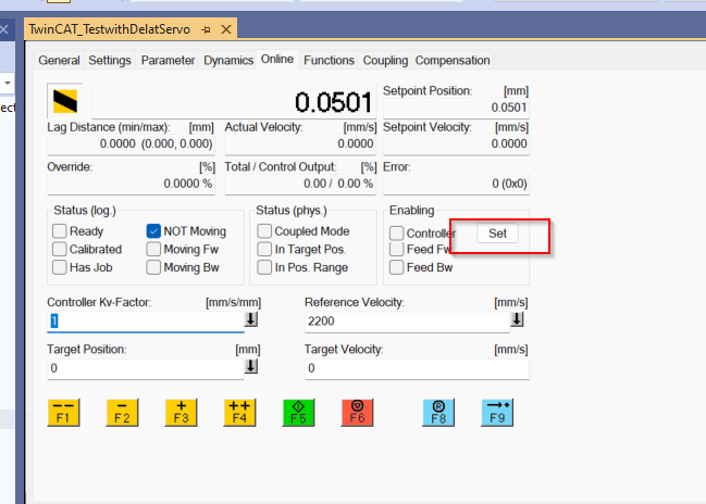
Select All and confirm with >Ok.
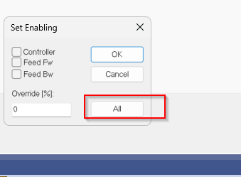
Done!Now ServoON is on, try Jog operation with F1/F2/F3/F4 etc. or positioning operation from Function Tab!
Implementation3
Now we can control Servo from the TwinCAT PLC program.
Beckhoff Side
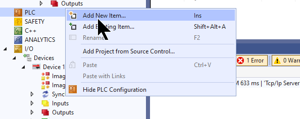
Add PLC Project
Add a PLC project by going to PLC>Right click>Add New Item.
Choose Standard PLC Project > Add to add a project.
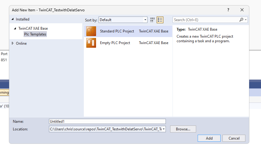
Done!PLC projects have been added.
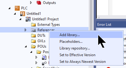
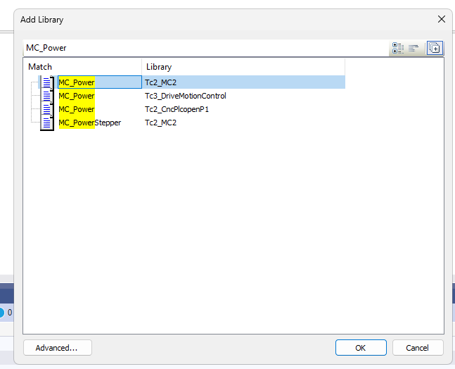
Add Library
Next, go to References>Add library to add the motion control library Tc2_MC2.
Configure Home Method
Select Delta Servo Drive>Startup>Right click>Add New Item to set initial parameters.
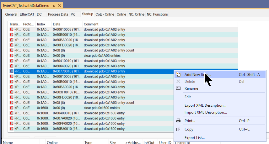
The Startup parameter setting screen appears.
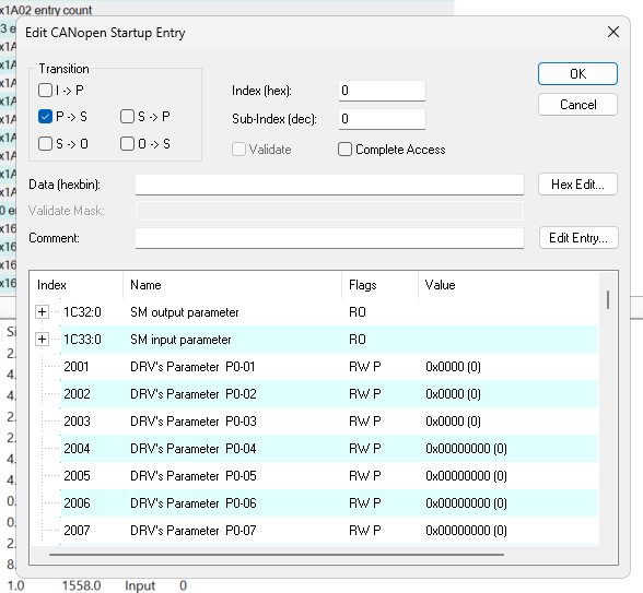
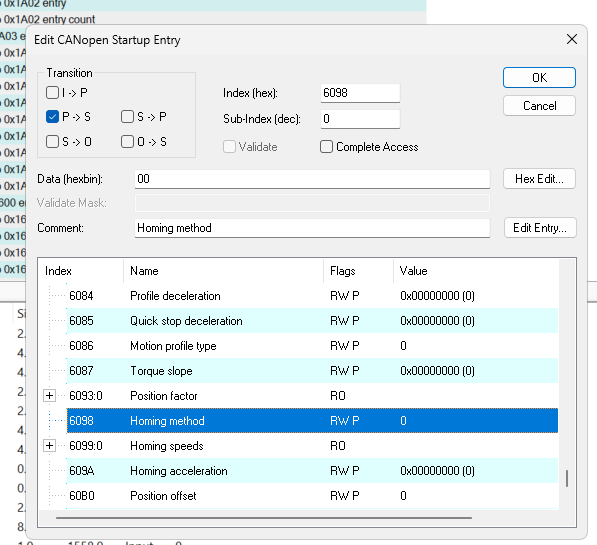
6098 is the Homing Method parameter, double-click on that parameter.
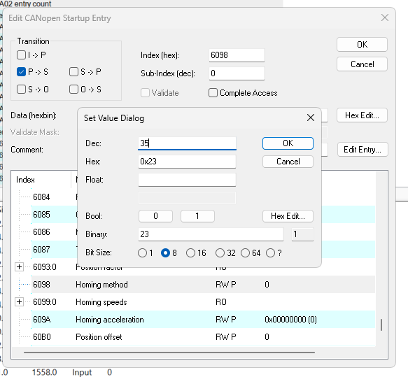
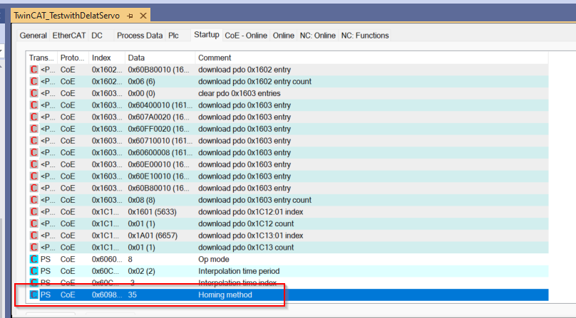
Set Value to 35 (35 = Direct Homing). 35 = Direct Homing, and there are various methods such as Servo moving backward to detect the origin sensor, but since the environment is Servo-only, Direct Homing is used.
Done!
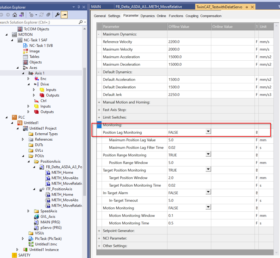
Lag Mode
Also, when not tuning first, Lag Monitor error alarms frequently occur, so temporarily set the Position Lag Monitoring function to False if necessary.
Program
Next, we will create a program. This time, we will create a program while stepping through a few OOP concepts such as Interface, Function Block, and Extend.
Interface
The first step is to create an interface, which allows you to focus only on “what” the Function Block is supposed to do and not on “how” it is supposed to do it. program and the “how” to do it. Interface can also be used to create a more unified program, with multiple different Function Blocks sharing only the same interface.
INTERFACE ITF_SpeedAxis
This defines “what to do” when controlling Servo speed.
METHOD METH_Half
This Method allows Servo to stop a running JOB.
| METHOD METH_Half : INT VAR_INPUT iCmd: BOOL; END_VAR |
METHOD METH_JogFWBW
The Method here is Servo’s JOG operation.
| METHOD METH_JogFWBW : INT VAR_INPUT iFw: BOOL; iBw: BOOL; iVelSetpoint: LREAL; iVelAcc: LREAL; iVelDec: LREAL; END_VAR |
METHOD METH_PowerON
The Method here is Servo ON operation.
| METHOD METH_PowerON : INT VAR_INPUT iCmd: BOOL; END_VAR |
METHOD METH_Reset
This Method is a Servo reset operation.
| METHOD METH_Reset : INT VAR_INPUT iCmd: BOOL; END_VAR |
METHOD METH_VelocityCmd
Method here is Servo’s constant speed operation.
| METHOD METH_VelocityCmd : INT VAR_INPUT iCmd: BOOL; iVelSetpoint: LREAL; iVelAcc: LREAL; iVelDec: LREAL; END_VAR |
PROPERTY Prop_CommunicationOK : BOOL
You can get Servo’s communication status from PROPERTY here.
PROPERTY Prop_Error : BOOL
You can get Servo’s error status from PROPERTY here.
PROPERTY Prop_MCState : ST_Axisstatus
Servo axis status can be obtained from PROPERTY here.
PROPERTY Prop_ReadActualPosition : lReal
You can get Servo’s current location from PROPERTY here.
PROPERTY Prop_ReadActualSpeed : lReal
You can get Servo’s current speed from PROPERTY here.
PROPERTY Prop_Ready : BOOL
You can get Servo’s ready signal from PROPERTY here.
PROPERTY Prop_Running : BOOL
You can get Servo’s on-the-move signal from PROPERTY here.
PROPERTY Prop_Stopped : BOOL
You can get Servo’s stop signal from PROPERTY here.
DUT
The next step is to define the structure.
eAxisBasicReturnValue
This is the return value of Method from this enumeration.
| {attribute ‘qualified_only’ := ”} {attribute ‘strict’ := ”} TYPE eAxisBasicReturnValue : ( init, ERROR, Done, Busy, nop, InVelocity ); END_TYPE |
Function Block
FB_Delta_ASDA_A3_SpeedAxis
This Function Block implements the ITF_SpeedAxis Interface defined earlier and defines instances of the necessary functions in Beckhoff’s Motion library.
| FUNCTION_BLOCK FB_Delta_ASDA_A3_SpeedAxis IMPLEMENTS ITF_SpeedAxis VAR_INPUT ioAxis: REFERENCE TO AXIS_REF; END_VAR VAR _MC_Power: MC_Power; _MC_Reset: MC_Reset; _MC_Half: MC_Halt; _MC_Jog: MC_Jog; _MC_MoveVelocity: MC_MoveVelocity; _MC_ReadActualPosition:MC_ReadActualPosition; _MC_ReadActualVelocity:MC_ReadActualVelocity; _MC_ReadStatus:MC_ReadStatus; END_VAR |
METHOD METH_Half
METHOD METH_Half : INT
This is the implementation of a Method to stop a running JOB.
| VAR_INPUT iCmd: BOOL; END_VAR VAR_INST R_TRIG:R_TRIG; END_VAR |
MC_Half is used to execute the job that the Servo axis is executing, and returns the appropriate return value according to the execution status and result of the Function Block.
| R_TRIG(CLK:=iCmd); _MC_Half( Axis:=ioAxis ,Execute:=iCmd ,Deceleration:=100.0 ); IF R_TRIG.Q THEN METH_Half:=eAxisBasicReturnValue.nop; END_IF; IF _MC_Half.Error THEN METH_Half:=eAxisBasicReturnValue.ERROR; ELSIF _MC_Half.Busy THEN METH_Half:=eAxisBasicReturnValue.Busy; ELSIF _MC_Half.Done THEN METH_Half:=eAxisBasicReturnValue.Done; END_IF |
METH_JogFWBW
This is an implementation of Method to operate SERVO’s JOB.
| METHOD METH_JogFWBW : INT VAR_INPUT iFw: BOOL; iBw: BOOL; iVelSetpoint: LREAL; iVelAcc: LREAL; iVelDec: LREAL; END_VAR VAR fw: BOOL; bw: BOOL; END_VAR VAR_INST R_TRIG:R_TRIG; END_VAR |
MC_Jog is used to execute Servo axis JOG operations and return appropriate return values according to the execution status and results of the Function Block.
| fw:=iFw AND NOT iBw; bw:=iBw AND NOT iFw; R_TRIG( CLK:=(iFw AND NOT iBw) OR (iBw AND NOT iFw) ); _MC_Jog( Axis:=ioAxis ,JogForward:=fw ,JogBackwards:=bw ,Velocity:=iVelSetpoint ,Acceleration:=iVelAcc ,Deceleration:=iVelDec ,Mode:=E_JogMode.MC_JOGMODE_CONTINOUS ); IF R_TRIG.Q THEN METH_JogFWBW:=eAxisBasicReturnValue.nop; END_IF; IF _MC_Jog.Error THEN METH_JogFWBW:=eAxisBasicReturnValue.ERROR; ELSIF _MC_Jog.Busy THEN METH_JogFWBW:=eAxisBasicReturnValue.Busy; END_IF |
METH_PowerON
This is the implementation of the SERVO ON operation.
| METHOD METH_PowerON : INT VAR_INPUT iCmd: BOOL; END_VAR VAR_INST R_TRIG:R_TRIG; END_VAR |
MC_Power is used to execute Servo ON/OFF of Servo axis and returns appropriate return value according to the execution status and result of Function Block.
| R_TRIG(CLK:=iCmd); _MC_Power( Axis:=ioAxis ,Enable:=iCmd ,Enable_Positive:=TRUE ,Enable_Negative:=TRUE ); IF R_TRIG.Q THEN METH_PowerON:=eAxisBasicReturnValue.nop; END_IF; IF _MC_Power.Error THEN METH_PowerON:=eAxisBasicReturnValue.ERROR; ELSIF _MC_Power.Busy THEN METH_PowerON:=eAxisBasicReturnValue.Busy; ELSIF _MC_Power.Enable THEN METH_PowerON:=eAxisBasicReturnValue.Done; END_IF |
METH_Reset
This is the implementation of the SERVO reset operation.
| METHOD METH_Reset : INT VAR_INPUT iCmd: BOOL; END_VAR VAR_INST R_TRIG:R_TRIG; END_VAR |
MC_Reset is used to execute Servo ON/OFF of Servo axis and returns appropriate return value according to the execution status and result of Function Block.
| R_TRIG(CLK:=iCmd); _MC_Reset( Axis:=ioAxis ,Execute:=iCmd ); IF R_TRIG.Q THEN METH_Reset:=eAxisBasicReturnValue.nop; END_IF; IF _MC_Reset.Error THEN METH_Reset:=eAxisBasicReturnValue.ERROR; ELSIF _MC_Reset.Busy THEN METH_Reset:=eAxisBasicReturnValue.Busy; ELSIF _MC_Reset.Done THEN METH_Reset:=eAxisBasicReturnValue.Done; END_IF |
METH_VelocityCmd
This is an implementation of SERVO’s constant speed operation.
| METHOD METH_VelocityCmd : INT VAR_INPUT iCmd: BOOL; iVelSetpoint: LREAL; iVelAcc: LREAL; iVelDec: LREAL; END_VAR VAR_INST R_TRIG:R_TRIG; END_VAR |
MC_MoveVelocity is used to execute Servo ON/OFF of Servo axis and returns appropriate return value according to the execution status and result of Function Block.
| R_TRIG(CLK:=iCmd); _MC_MoveVelocity( Axis:=ioAxis ,Execute:=iCmd ,Velocity:=iVelSetpoint ,Acceleration:=iVelAcc ,Deceleration:=iVelDec ); IF R_TRIG.Q THEN METH_VelocityCmd:=eAxisBasicReturnValue.nop; END_IF; IF _MC_MoveVelocity.Error THEN METH_VelocityCmd:=eAxisBasicReturnValue.ERROR; ELSIF _MC_MoveVelocity.Busy THEN METH_VelocityCmd:=eAxisBasicReturnValue.Busy; ELSIF _MC_MoveVelocity.InVelocity THEN METH_VelocityCmd:=eAxisBasicReturnValue.InVelocity; END_IF |
PROPERTY Prop_CommunicationOK : BOOL
This property determines whether communication is OK from the IodataInvalid variable.
| Prop_CommunicationOK:=not ioAxis.Status.IoDataInvalid; |
PROPERTY Prop_Error : BOOL
This property determines if communication is OK from the Error variable.
| Prop_Error:=ioAxis.Status.Error; |
PROPERTY Prop_MCState : Tc2_MC2.ST_AxisStatus
This Property here uses MC_ReadStatus to obtain the status of the axis.
| _MC_ReadStatus( Axis:=ioAxis ,Enable:=TRUE ); Prop_MCState:=_MC_ReadStatus.Status; |
PROPERTY Prop_ReadActualPosition : LREAL
This property uses MC_ReadActualPosition to obtain the current position of the axis.
| _MC_ReadActualPosition( Axis:=ioAxis ,Enable:=True ); Prop_ReadActualPosition:=_MC_ReadActualPosition.Position; |
PROPERTY Prop_ReadActualSpeed : LREAL
This property uses MC_ReadActualVelocity to obtain the current velocity of the axis.
| _MC_ReadAutualVelocity( Axis:=ioAxis ,Enable:=TRUE); Prop_ReadActualSpeed:=_MC_ReadAutualVelocity.ActualVelocity; |
PROPERTY Prop_Ready : BOOL
This property determines Servo’s ready status from the Ready variable.
| Prop_Ready:=ioAxis.Status.Operational; |
PROPERTY Prop_Running : BOOL
This property determines whether Servo is moving from the Ready variable.
| Prop_Running:=ioAxis.Status.Moving; |
PROPERTY Prop_Stoppped : BOOL
This property determines whether Servo is stopped from the Ready variable.
| Prop_Stoppped:=ioAxis.Status.NotMoving; |
Program-Position Axis
We have just defined a Function Block for SpeedAxis, but since we want to do this for simple positioning in this article, we will also create a new Function Block, Interface, and extend it from the original Interface and FB.
Interface‐ITF_PositionAxis
Let’s define a new Interface and extend it from INTERFACE ITF_SpeedAxis.
METHOD METH_Home
This Method can be Home Servo.
| METHOD METH_Home : INT VAR_INPUT iCmd: BOOL; END_VAR |
METHOD METH_MoveAbs
This Method implements an absolute positioning operation on Servo.
| METHOD METH_MoveAbs : INT VAR_INPUT iCmd: BOOL; iVelSetpoint: LREAL; iVelAcc: LREAL; iVelDec: LREAL; iPosition: LREAL; END_VAR |
METHOD METH_MoveRelative
This Method implements a relative positioning operation on Servo.
| METHOD METH_MoveRelative : INT VAR_INPUT iCmd: BOOL; iVelSetpoint: LREAL; iVelAcc: LREAL; iVelDec: LREAL; iDistance: LREAL; END_VAR |
Function Block
Next, let’s create a FB for positioning.
FB_Delta_ASDA_A3_PositionAxis
This FB here extends the FB_Delta_ASDA_A3_SpeedAxis created earlier and also implements ITF_PositionAxis. We will also define the necessary functions in the Beckhoff Motion library.
| FUNCTION_BLOCK FB_Delta_ASDA_A3_PositionAxis EXTENDS FB_Delta_ASDA_A3_SpeedAxis IMPLEMENTS ITF_SpeedAxis, ITF_PositionAxis VAR _MC_MoveAbsolute: MC_MoveAbsolute; _MC_MoveRelative: MC_MoveRelative; _MC_Home: MC_Home; END_VAR |
METH_Home
This is an implementation of Method to operate SERVO’s HOME.
| METHOD METH_Home : INT VAR_INPUT iCmd: BOOL; END_VAR VAR_INST R_TRIG:R_TRIG; END_VAR |
MC_Home is used to execute the Servo axis Home operation and return the appropriate return value according to the execution status and result of the Function Block.
| R_TRIG(CLK:=iCmd); _MC_Home( Axis:=ioAxis ,Execute:=iCmd ,Position:=0.0 ,HomingMode:=MC_HomingMode.MC_Direct ); IF R_TRIG.Q THEN METH_Home:=eAxisBasicReturnValue.nop; END_IF; IF _MC_Home.Error THEN METH_Home:=eAxisBasicReturnValue.ERROR; ELSIF _MC_Home.Busy THEN METH_Home:=eAxisBasicReturnValue.Busy; ELSIF _MC_Home.Done THEN METH_Home:=eAxisBasicReturnValue.Done; END_IF |
METH_MoveAbs
MC_MoveAbsolute is used to perform absolute positioning of the Servo axis and returns the appropriate return value according to the execution status and result of the Function Block.
| METHOD METH_MoveAbs : INT VAR_INPUT iCmd: BOOL; iVelSetpoint: LREAL; iVelAcc: LREAL; iVelDec: LREAL; iPosition: LREAL; END_VAR VAR_INST R_TRIG:R_TRIG; END_VAR |
| R_TRIG(CLK:=iCmd); _MC_MoveAbsolute( Axis:=ioAxis ,Execute:=iCmd ,Position:=iPosition ,Velocity:=iVelSetpoint ,Acceleration:=iVelAcc ,Deceleration:=iVelDec ); IF R_TRIG.Q THEN METH_MoveAbs:=eAxisBasicReturnValue.nop; END_IF; IF _MC_MoveAbsolute.Error THEN METH_MoveAbs:=eAxisBasicReturnValue.ERROR; ELSIF _MC_MoveAbsolute.Busy THEN METH_MoveAbs:=eAxisBasicReturnValue.Busy; ELSIF _MC_MoveAbsolute.Done THEN METH_MoveAbs:=eAxisBasicReturnValue.Done; END_IF |
METH_MoveRelative
MC_MoveRelative is used to execute relative positioning of the Servo axis and return the appropriate return value according to the execution status and result of the Function Block.
| METHOD METH_MoveRelative : INT VAR_INPUT iCmd: BOOL; iVelSetpoint: LREAL; iVelAcc: LREAL; iVelDec: LREAL; iDistance: LREAL; END_VAR VAR_INST R_TRIG:R_TRIG; END_VAR |
| R_TRIG(CLK:=iCmd); _MC_MoveRelative( Axis:=ioAxis ,Execute:=iCmd ,Distance:=iDistance ,Velocity:=iVelSetpoint ,Acceleration:=iVelAcc ,Deceleration:=iVelDec ); IF R_TRIG.Q THEN METH_MoveRelative:=eAxisBasicReturnValue.nop; END_IF; IF _MC_MoveRelative.Error THEN METH_MoveRelative:=eAxisBasicReturnValue.ERROR; ELSIF _MC_MoveRelative.Busy THEN METH_MoveRelative:=eAxisBasicReturnValue.Busy; ELSIF _MC_MoveRelative.Done THEN METH_MoveRelative:=eAxisBasicReturnValue.Done; END_IF |
GVL_Axis
Add the Global Variables List and define the AXIS_REF variable.
| {attribute ‘qualified_only’} VAR_GLOBAL axies:ARRAY[0..9]OF AXIS_REF; END_VAR |
Program-pServo
This is the main program, which calls the Function Block created earlier and repeats absolute and relative positioning using CASE statements.
| PROGRAM pServo VAR Axis1: FB_Delta_ASDA_A3_PositionAxis; Status:ST_AxisStatus; ActVelocity,ActPosition:LREAL; bFw: BOOL; bBw: BOOL; bHome: BOOL; bMoveAbs: BOOL; bMoveRelative: BOOL; bCommunicationOK: BOOL; bError: BOOL; bRunning: BOOL; bStopped: BOOL; bPowerON: BOOL; bReset: BOOL; RetValue: INT; RetValueAbs: INT; RetValueRet:INT; bReady: BOOL; bRun: BOOL; bStop: BOOL; fSetValue: REAL; f32AbsPos: REAL; f32AbsVel: REAL:=100.0; f32AbsAcc: REAL:=100.0; f32AbsDec: REAL:=100.0; f32RelativePos: REAL; f32RelativeVel: REAL:=100.0; f32RelativeAcc: REAL:=100.0; f32RelativeDec: REAL:=100.0; // iStep:INT; TON:TON; iStart:BOOL; iStop:BOOL; myCounter:INT; END_VAR |
| //Axis of Delta Servo Axis1(ioAxis:=GVL_Axis.axies[0]); //Power ON the Axis RetValue:= Axis1.METH_PowerON( iCmd:=bPowerON ); //Get the Status //Ready bReady:=Axis1.Prop_Ready; //Running bRunning:=Axis1.Prop_Running; //Error bError:=Axis1.Prop_Error; //Stopped bStopped:=Axis1.Prop_Stopped; //CommunicationOK bCommunicationOK:=Axis1.Prop_CommunicationOK; //Status Status:=Axis1.Prop_MCState; //ActSpeed ActVelocity:=Axis1.Prop_ReadActualSpeed; //ActPostion ActPosition:=Axis1.Prop_ReadActualPosition; //Reset RetValue:=Axis1.METH_Reset( iCmd:=bReset ); IF RetValue = eAxisBasicReturnValue.Busy THEN bReset:=FALSE; END_IF //Halt RetValue:=Axis1.METH_Half( iCmd:=bStop ); IF Status.Stopping OR bError THEN bStop:=FALSE; END_IF //Home RetValue:=Axis1.METH_Home( iCmd:=bHome ); //MoveVelocity RetValue:=Axis1.METH_VelocityCmd( iCmd:=bRun ,iVelSetpoint:=fSetValue ,iVelAcc:=100.0 ,iVelDec:=100.0 ); //Jog RetValue:=Axis1.METH_JogFWBW( iFw:=bFw AND NOT bBw ,iBw:=bBw AND NOT bFw ,iVelSetpoint:=fSetValue ,iVelAcc:=100.0 ,iVelDec:=100.0 ); //MoveAbsolute RetValueAbs:=Axis1.METH_MoveAbs( iCmd:=bMoveAbs ,iVelSetpoint:=f32AbsVel ,iVelAcc:=f32AbsAcc ,iVelDec:=f32AbsDec ,iPosition:=f32AbsPos ); //MoveRelative RetValueRet:=Axis1.METH_MoveRelative( iCmd:=bMoveRelative ,iVelSetpoint:=f32RelativeVel ,iVelAcc:=f32RelativeAcc ,iVelDec:=f32RelativeDec ,iDistance:=f32RelativePos ); // IF Status.Moving OR bError THEN bRun:=FALSE; bMoveAbs:=FALSE; bMoveRelative:=FALSE; END_IF CASE iStep OF 0: iStop:=FALSE; IF iStart AND iStep =0 THEN iStep:=10; iStart:=FALSE; myCounter:=0; END_IF 10: bMoveAbs:=TRUE; f32AbsPos:=1000.0; IF GVL_Axis.axies[0].Status.Moving THEN iStep:=20; bMoveAbs:=FALSE; END_IF 20: IF RetValueAbs = eAxisBasicReturnValue.Done THEN iStep:=30; END_IF 30: bMoveRelative:=TRUE; f32RelativePos:=-200.0; IF GVL_Axis.axies[0].Status.Moving THEN iStep:=40; bMoveRelative:=FALSE; END_IF 40: IF RetValueRet = eAxisBasicReturnValue.Done THEN IF NOT iStop THEN IF myCounter >3 THEN iStep:=10; myCounter:=0; ELSE myCounter:=myCounter+1; iStep:=30; END_IF; ELSE iStep:=0; END_IF; END_IF END_CASE |
Program-Main
The last step is to call the pServo POU you just created in the MAIN program.
| PROGRAM MAIN VAR END_VAR |
| pServo(); |
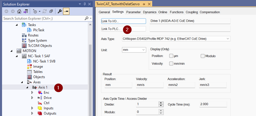
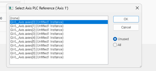
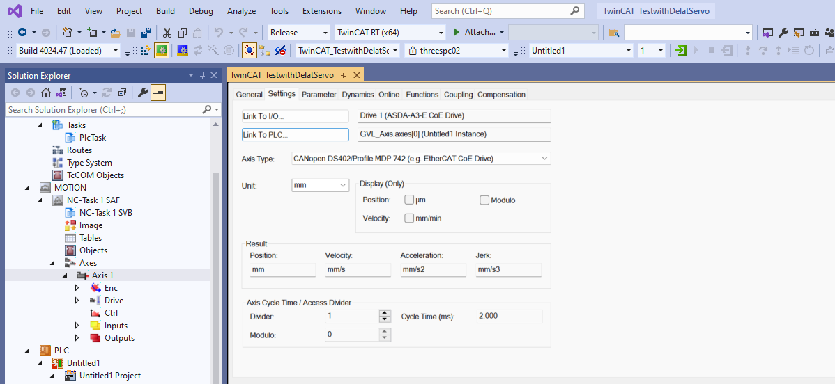
Link to PLC
Click Axis>Settings>Link to PLC to connect AXIS_REF and AXIS as defined in the Global Variables List.
Done!
Active Configuration
Click Active Configuration and Download the project once to Runtime.
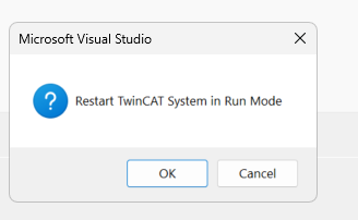
OK to proceed.
OK to shift TwinCAT Runtime to Run Mode.
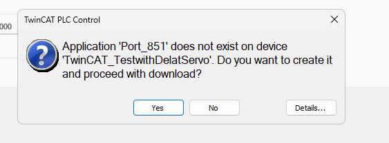
Login
Download the program in Login.

Let’s proceed with Yes.
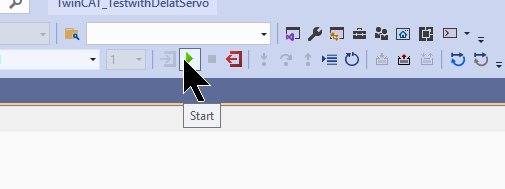
Start
Finally, the Start button executes the Runtime program.
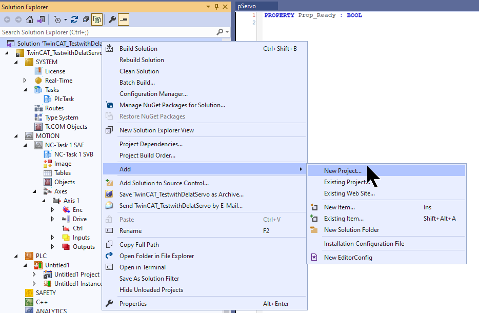
Add Scope Project
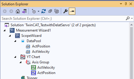
Finally, add a Scope project and monitor the TwinCAT Runtime variables in real time by clicking Solution>Right click>Add>New Project.
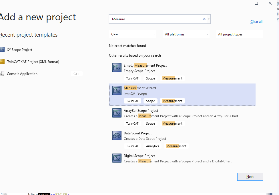
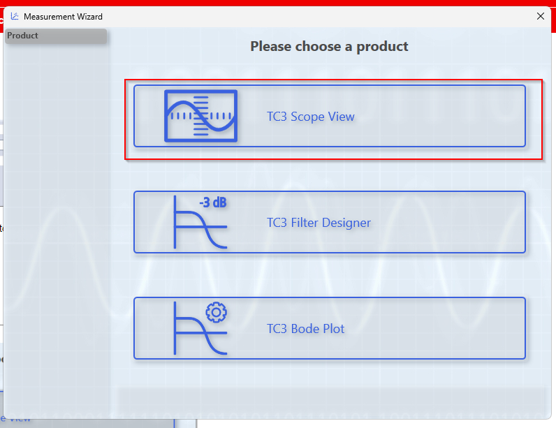
Select Measurement Wizard >Next to proceed.
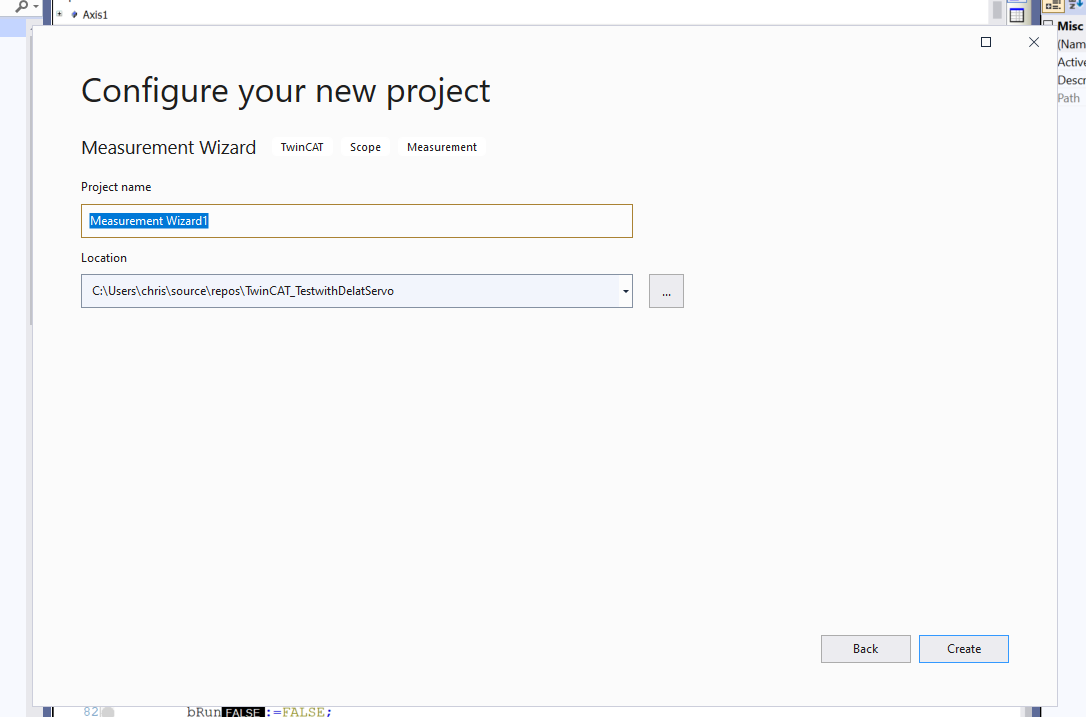
Enter a project name for Measurement and proceed with Create.
In this case, TC3 Scope View will be used.
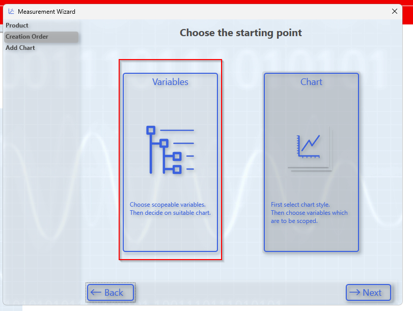
Click Variables to set the variables you want to monitor.
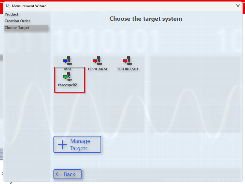
Select the Target system whose variables you want to monitor.
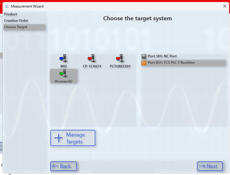
This time, we want to monitor PLC Runtime variables, so select Port 851 and press Next to proceed.
You can list variables in the PLC runtime.
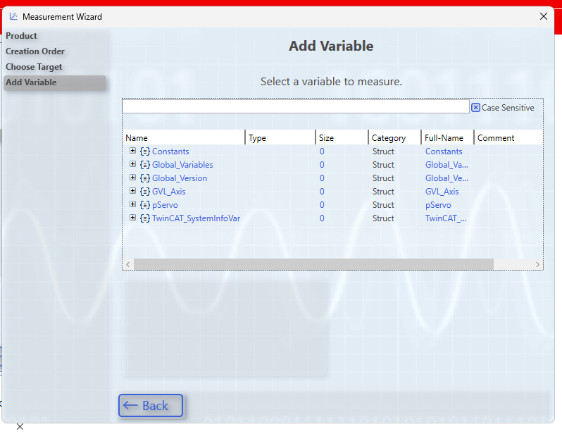
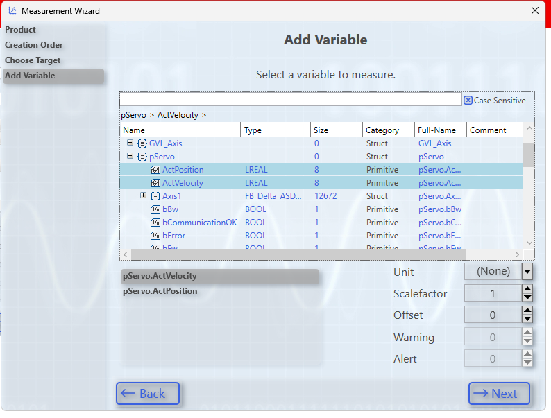
Next, select the variable to be monitored and proceed with Next.
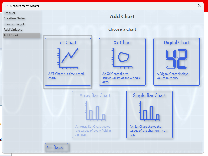
Use Time-based Chart.
Create a Chart with the Create button.
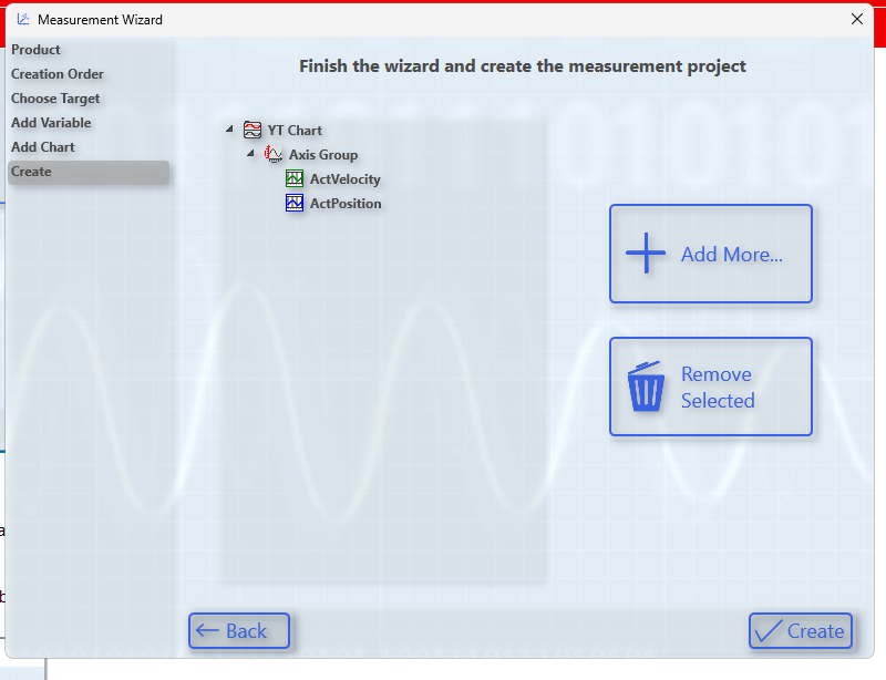
Done!
If you want to record a variable, click the Start Record button.
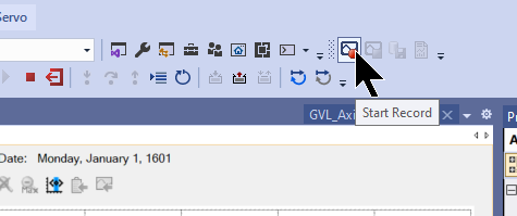
Done!!
If you want to abort the record, click on Stop Record.
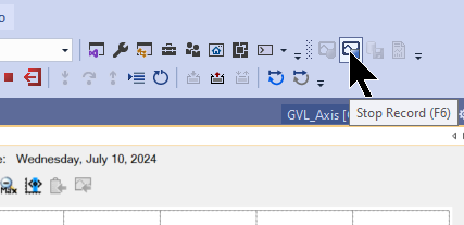
Let’s stop the record with OK.
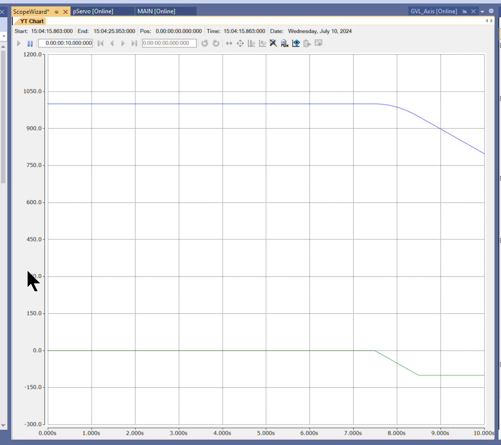
Result
You can check the operation from this video.
Download the article project from this Link.
https://github.com/soup01Threes/TwinCAT3/blob/main/TwinCAT_TestwithDelatServo.tnzip