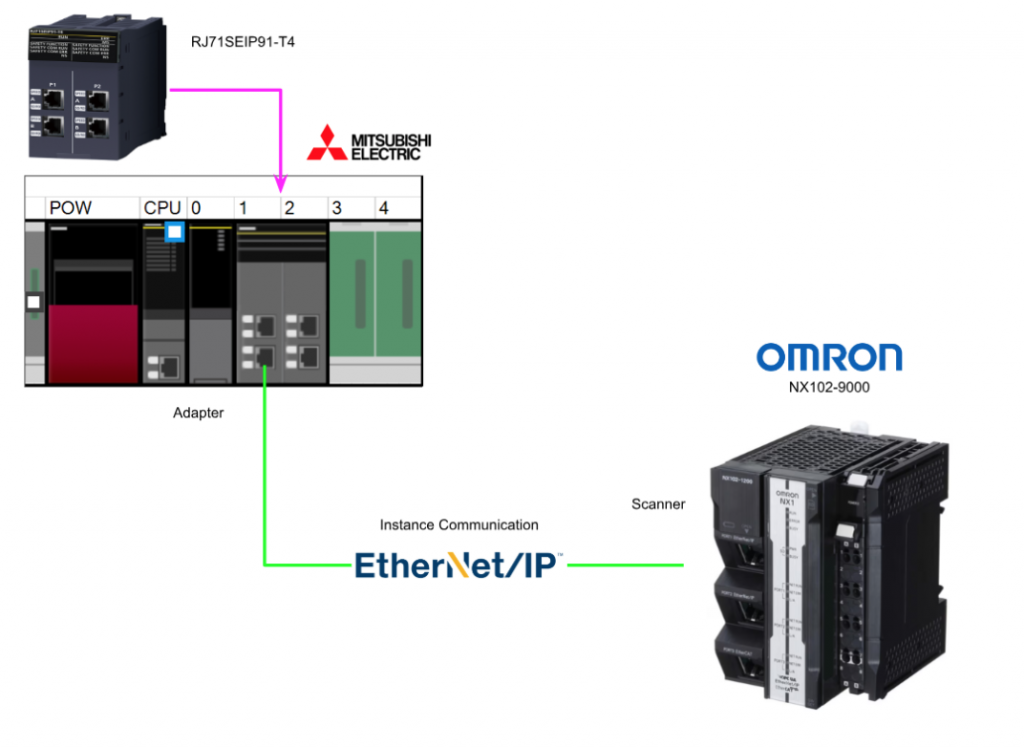
This is a new article series, which uses Mitsubishi’s RJ71SEIP91-T4 for various communication tests.The RJ71SEIP91-T4 is the Adapter and the OMRON NX1-9000 is the Scanner.
Come on, let’s enjoy FA.
Reference Link
Reference Video
Mitsubishi.Open box with RJ71SEIP91-T4!
Implementation
Let’s Build your project with this configuration.

IQR Side
First build the IQ-R side from Mitsubishi Electric.
Register Profile
Download the Profile of RJ71SEIP91-T4 from Mitsubishi Electric’s website.
https://emea.mitsubishielectric.com/fa/products/cnt/plc/allcpu/rj71seip91-t4.html#downloads
Next, click on Tool>Profile Managment>Register to register the Profile to GXWORKS3.
Select the file XXXX.ipar that you have just downloaded.
Done!Profile registration for RJ71SEIP91-T4 was successful.
Install Module Label
Next, to install the RJ71SEIP91-T4 Module Label in GXWORKS3, download the RJ71SEIP91-T4.mslu from C:\Program Files (x86)\MELSOFT\MSF\Common\Library\UNITFB Directory.
Next, run C:\Program Files (x86)\MELSOFT\GPPW3\GXW3PluginPreloader.exe with administrator privileges.
Install Configuration Tools
To build the RJ71SEIP91-T4 module, you need to use the dedicated Configuration Tools, please download the RJ71SEIP91-T4 CIP Safety Configuration Tool from the Link below.
https://emea.mitsubishielectric.com/fa/products/cnt/plc/allcpu/rj71seip91-t4.html#downloads
Unzip the ZIP File you just downloaded and click on Setup,exe.
Proceed with Next>.
Set the installation location for the CIP Safety Configuration Tool and proceed with Next>.
Click Install to start setting up the CIP Safety Configuration Tool.
Please wait a moment…
Proceed with Yes to pass the Packets in the CIP Safety Configuration Tool through the Firewall.
Done!
Create New Project
Start GXWORKS3 and add a new project by going to Project>New.
The R32SF Safety PLC was used in this article.
To use the Safety PLC, a User name and Password must be set in the project.
Set User name and Password, and press “Ok” to proceed.
Once the project is created, click Setting Change.
Put on the Use Module Label Option.
Done!A project has been created.
Module Configuration
To configure Hardware Configuration, click on Module Configuration.
This is the Module Configuration screen.
Add R35B
Drop IQ-R Series>Main Base>R35B and add the Base Unit used in this article.
Done!
Add R61P
The next step is to add the power supply module used in this article at Power Supply>R61P.
Done!
Add PLC into PLC Rack
Drop the R32SF Safety PLC into the CPU Slot.
Done!So I installed the CPU in Rack.
Add R6SFM
CPU Extension>R6SFM to add CPU safety extension units.
Done!
Add RJ71SEIP91-T4
Finally, drop Network>RJ71SEIP91-T4 into Slot1.
Done!
Save the Configuration
Next, save the Module Configuration.
OK to proceed.
M+Global
Since we have just enabled the Module Label use setting, a Global Variable List named Label>Global Label>M+Global has been added.
M+Global has now defined labels for the CPUs and modules used in this article (RJ71SEIP91-T4, of course).
Check your Configuration
Convert>Rebuild All once to check for Hardware Configuration problems.
Reset User
Let’s initialize the PLC data and reset all the data in case you forgot the Password of the R32SF Safety PLC main unit, click Online>User Authentication>Initialize all PLC Data.
Write User Data
Next, in order to write the User Data for this project to the CPU, go to Online>User Authentication>Write User information to PLC to write the User data to R32SF Safety PLC.
Proceed with Yes.
Proceed further with Yes.
Done!
Write to PLC
Execute Online>Write to PLC to write the Hardware Configuration to the CPU once.
Check RJ71SEIP91-T4 IP Address
Click Diagnosis>System Monitor to see the IP address of the current RJ71SEIP91-T4.
Double-click the RJ71SEIP91-T4 module.
You can check the diagnostic information of RJ71SEIP91-T4 and open the Module Information List Tab.
Detailed information on RJ71SEIP91-T4 is displayed and P1=192.168.250.11 is confirmed.
Configure Ethernet/IP Network
Next, to build the Ethernet/IP network, double-click RJ71SEIP91-T4>CIP Safety Configuration Tool to launch the tool.
Setup the Local Adapter
Select the Safety Communication Module and go to >General>Local Network interface IP address to use and set the Ethernet Port to communicate with the RJ71SEIP91-T4.
Configure the appropriate Ethernet interface (your PC) from the Drop-List.
Done!
Configure Network1
The RJ71SEIP91-T4 used in this article is Port 1 of the RJ71SEIP91-T4, and as written on the RJ71SEIP91-T4 itself, Port A and Port B marked with P1 are Network 1, and Port A and Port B marked with P2 are Network 2.
Click Network1.
Detect the Network1
Find RJ71SEIP91-T4 under General>Scanner IP Address Settings>Detect.
Done!The IP address of the Port currently connected to the PC and RJ71SEIP91-T4 is shown in the Idnetifier column (192.168.250.11).
Next, OK to apply the settings.
Done!RJ71SEIP91-T4 Port1 IP address setting is reflected.
Ping Network1
Ping>Send Ping to confirm communication with Network1 of RJ71SEIP91-T4.
Done!Ping command passed.
Configure Class1 Connection
Next, put a Checkbox in General>Target(Class1) to add an Instance for Class1 Connection to RJ71SEIP91-T4.
A tab named “Target(Class 1)” has been added to the CIP Safety Configuration Tool.
Here you can add/delete/edit the Tag and Instance of Class1.
Add Instance
This article will use Class 1 Instance communication, so add a new Instance with Target(Class 1 Instance)>Add.
Done!The number under the Connection can specify the Identifier of the corresponding Connection.
T->O Size and O->T Size are set to 20Bytes each this time.
Transfer the Configuration
Transfer the Hardware Configuration from the CIP Safety Configuration Tool to the RJ71SEIP91-T4: Safety Communication Module>General>Save configuration to ModuleClick Safety Communication Module>General>Save configuration to Module and transfer the configuration to RJ71SEIP91-T4.
Proceed with Yes.
Please wait a moment…
Done!
Close the Application
Remember to close the CIP Safety Configuration Tool.
Program
The next step is to create a program.
| IF RJ71SEIP91_1.stEIPCls1_P1.uSet_CommunicationStartupRequest_D = 0 AND RJ71SEIP91_1.bSts_ModuleReady THEN RJ71SEIP91_1.stEIPCls1_P1.uSet_CommunicationStartupRequest_D := 1; END_IF; FOR iCounter:=0 TO 9 DO RJ71SEIP91_1.stEIPCls1_P1.unArea_Class1OutputDataArea_D[iCounter]:=0; END_FOR; IF NOT RJ71SEIP91_1.stEIPCls1_P1.bnSts_Class1Error_Connection_D[1] THEN RJ71SEIP91_1.stEIPCls1_P1.unArea_Class1OutputDataArea_D[0]:=12; RJ71SEIP91_1.stEIPCls1_P1.unArea_Class1OutputDataArea_D[1]:=34; RJ71SEIP91_1.stEIPCls1_P1.unArea_Class1OutputDataArea_D[2]:=56; RJ71SEIP91_1.stEIPCls1_P1.unArea_Class1OutputDataArea_D[3]:=78; RJ71SEIP91_1.stEIPCls1_P1.unArea_Class1OutputDataArea_D[4]:=90; RJ71SEIP91_1.stEIPCls1_P1.unArea_Class1OutputDataArea_D[5]:=123; RJ71SEIP91_1.stEIPCls1_P1.unArea_Class1OutputDataArea_D[6]:=124; RJ71SEIP91_1.stEIPCls1_P1.unArea_Class1OutputDataArea_D[7]:=125; RJ71SEIP91_1.stEIPCls1_P1.unArea_Class1OutputDataArea_D[8]:=126; RJ71SEIP91_1.stEIPCls1_P1.unArea_Class1OutputDataArea_D[9]:=127; END_IF; |
Write
Download your project to the CPU by going to Online>Write to PLC.
Reset Power
Finally, turn the IQ-R CPU back on.
OMRON Side
The next step is to build the OMRON NX102-9000 side.
Download EDS File
Download the EDS File for Mitsubishi’s RJ71SEIP91-T4 at the Link below.
https://emea.mitsubishielectric.com/fa/products/cnt/plc/allcpu/rj71seip91-t4.html#downloads
New Project
Start Sysmac Studio and create a new project.
Configure IP Address
Open Configuration and Setup>Controller Setup>build in EtherNet/IP Port and set the IP address according to your application.
Global Variables
Next, add a Global variable.
Defines the input/output data to be exchanged with Mitsubishi’s RJ71SEIP91-T4.Remember then to set Input and Output in Network Publish.
Program
The next step is to create a simple communication verification program.
| DataToEagle[0]:=220; DataToEagle[1]:=221; DataToEagle[2]:=222; DataToEagle[3]:=223; DataToEagle[4]:=224; DataToEagle[5]:=225; DataToEagle[6]:=226; DataToEagle[7]:=227; DataToEagle[8]:=228; DataToEagle[9]:=229; ; |
Ethernet/IP Setting
Open Tools>EtherNet/IP Connection Settings to configure Ethernet/IP connection settings.
You will see the network settings of your NX1CPU and other information.
Since Network1 was used in this article, right-click Port>Edit.
Install EDS File
The next step is to install the EDS File for RJ71SEIP91-T4.
Click the “Install” button at the bottom.
Install the RJ71SEIP91-T4 EDS File downloaded from Mitsubishi’s website.
Done!
Resigter
Now enter the Tag Set screen and click on Registration All to publish the variables in the project for use in the Ethernet/IP network.
Select all Tags and proceed with Register.
Done!
Add RJ71SEIP91-T4
Now click the + button in the Toolbox to add RJ71SEIP91-T4.
Switch to the Ethernet/IP Node Settings screen.
Node Address
Node Address is set to the IP address of Mitsubishi’s RJ71SEIP91-T4.
Model Name
The Model Name should of course be set to RJ71SEIP91-T4.
Revision
There is only one Revision.
Add RJ71SEIP91-T4
Finally, add an Ethernet/IP Node using the Add button at the bottom of the Toolbox.
Done!
Let’s go ahead and add the RJ71SEIP91-T4 that we just added.
Configure Connection
Sets parameters for connection to RJ71SEIP91-T4.
INPUT/Originator Variable
The INPUT/Originator Variable defines the variable to be transferred to the data coming from the RJ71SEIP91-T4. In this example, it is set to DataFromEagle.
OUTPUT/Originator Variable
The OUTPUT/Originator Variable defines the variable for the data to be sent to the RJ71SEIP91-T4. In this example, it is set to DataToEagle.
Open EDS File via EZ
We want to know the Instance number of the RJ71SEIP91-T4, so open the RJ71SEIP91-T4 EDS File in the EZ-EDS tool. Since we want to use the Exclusive Owner connection for this article, click Connection Manager>Connection1.
Scroll to the bottom to see the connection Path for Connection1 Exclusive Owner.
There are two variables there, Param21 and Param20.
Param21=Output data of RJ71SEIP91-T4 and Param20=Input data of RJ71SEIP91-T4.
Once you open the Params item from the EZ-EDS tool, open Param21-Assembly instance O->T.
Min Value is 1024, Max is 1087, and Default is clearly stated as 1024, so we know that Param21 starts at 1024. In the previous article, we said that RJ71SEIP91-T4 has a maximum number of Class 1 communications per Port up to 64. 1024+64-1=1087, which is exactly 64Connection.
Next, open Param20-Assembly instance T->O. It clearly states that Min Value is 768, Max is 831, and Default is 768, so we know that Param20 starts at 768. In the previous article, I said that RJ71SEIP91-T4 has a maximum number of Class 1 communications per Port up to 64. 768+64-1=831, which is exactly 64Connection.
Input Target Variable
Now that we know the Instance number of RJ71SEIP91-T4, let’s set the Instance number in Target Variable.
You have just grasped that 1024 is Default in Param21.
We are going to connect the OMORN PLC to the Identifier 1 Connection of the RJ71SEIP91-T4, so enter 1024 here.
Input Byte Size
The Mitsubishi side set the data size of RJ71SEIP91-T4 to 20Bytes, so the OMRON side should go with that.
Output Target Variable
Now that we know the instance number of RJ71SEIP91-T4, let’s set the instance number in the Output Target Variable. So let’s enter 768 here.
That’s what you were able to figure out earlier with Param20 that 768 is Default.
Output Byte Size
The Mitsubishi side set the data size of RJ71SEIP91-T4 to 20Bytes, so the OMRON side should go with that.
Connection Type
The Mitsubishi side set the data size of RJ71SEIP91-T4 to 20Bytes, so the OMRON side should go with that.
RPI
The RPI should be set according to the application and network load.
Go Online
Controller>Online.
Transfer Ethernet/IP Setting
Transfers Ethernet/IP settings to the OMRON NX1 CPU.
Proceed with Yes.
This time, we want to stop the CPU and execute the transfer, so click “Change to PROGRAM mode and execute the transfer.
Just a second..
Yes restores the CPU to its original state.
Transfer Project
Now transfer the entire project to the CPU by clicking Controller>Transfer>To Controller.
Proceed with Execute.
Proceed with Yes.
Just a second..
Done!Click Yes to switch the CPU to RUN.
Done!
Result
Finally, we want to check the communication, so right-click on the Port while Sysmac Studio is online > Monitor.
Status Tab shows that it is communicating with RJ71SEIP91-T4.
Connection Status also shows no errors.
Tag Status confirmed that it is OK for two Tags, DataFromEagle and DataToEagle.
Output Tag Set/Input Tag Set TabCurrently, the communication status of all tags can be checked.
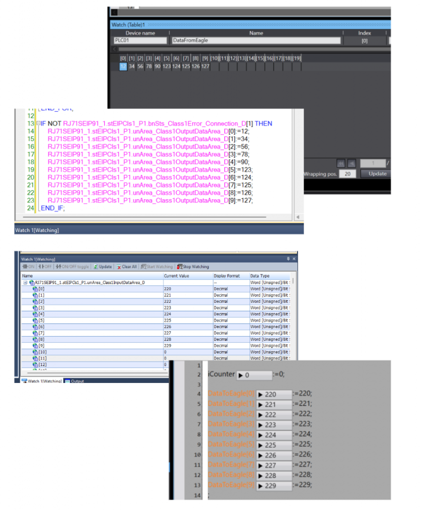
I was also able to confirm the current value of the data being exchanged with Mitsubishi RJ71SEIP91-T4.

Wireshark also showed that CIP IO Message is exchanging.