This article explains from scratch the setup and features of the AXL E IOL SDI8 SDO4 2A M12 IO-Link Over Profisafe module and Siemens PLC, recently launched by Phoenix Contact.
Let’s get started!
AXL E IOL SDI8 SDO4 2A M12 L?
The AXL E IOL SDI8 SDO4 2A M12 L module from Phoenix Contact is a safe input/output device for the Axioline E product line and can be used in the field according to protection class IP65/IP67. The module can be used in PROFIsafe systems and still be used in the field.
The module has 8 safe digital inputs and 4 safe digital outputs.

Layout
This is the Layout for AXL E IOL SDI8 SDO4 2A M12 L.
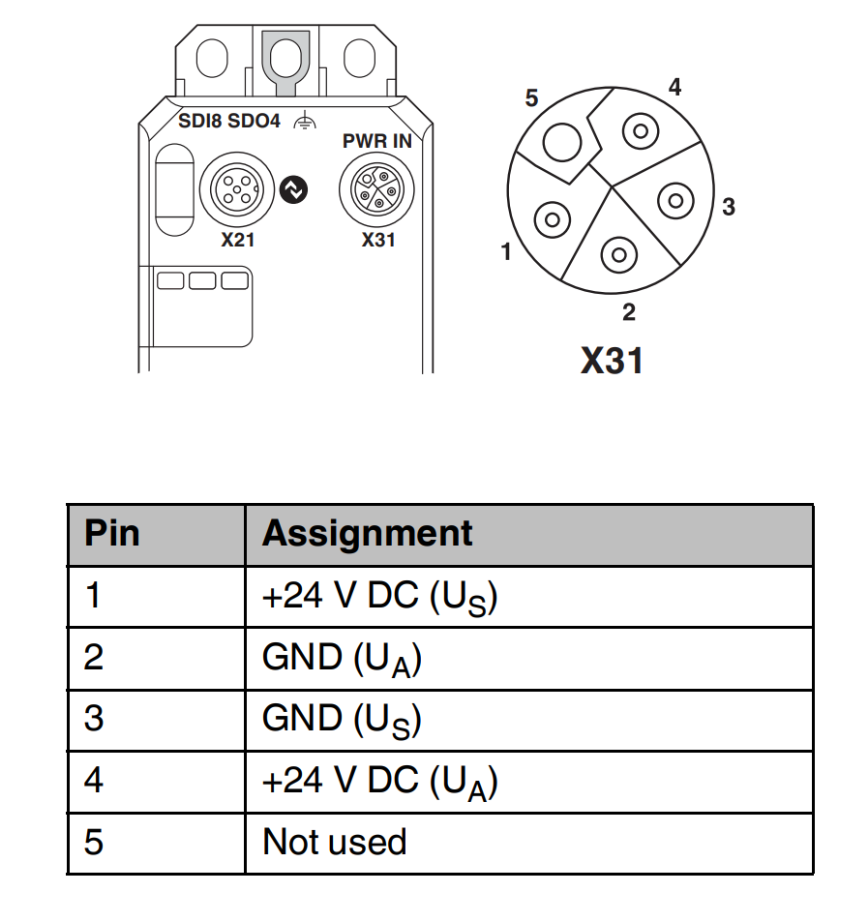
X31 PWR Port
X31 is an M12 male L Code with Power Port.
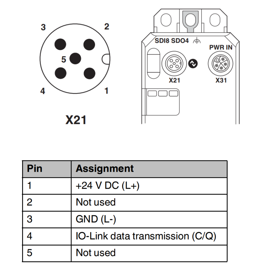
X21 IO-Link port
X21 is an IO-Link Port with M12 male A Code.
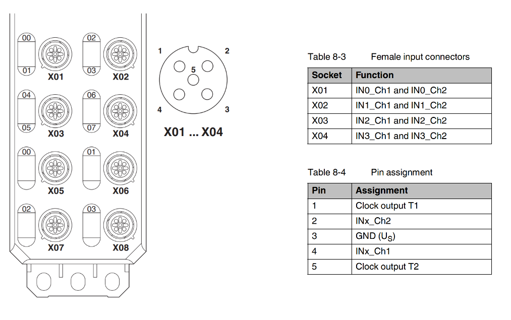
X01..X04 Safe Inputs Port
X01…X04 is a safety input Port and is an M12 female A Code.
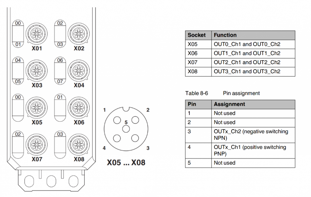
X05..X08 Safe Inputs Port
X05…X08 is a safety output Port with M12 female A Code.
Setting the safety address
There are two ways to set the safety address for AXL E IOL SDI8 SDO4 2A M12 L.
- Safety Address Assignment via Controller’s FB
- AXL E ADDRESSPLUG address plug is used for address assignment. It is possible after writing the safety address using FB.
Via FB
If via FB, you need to import the library provided by Phoenix Contact from Siemens S7 Controller and then write the F-Address to the module via FB.
Note that if the Address plug is not installed, the address is stored in the module as non-volatile.If the Address plug is installed, the address is not stored in the module.
Via the address plug
It is easy when replacing a device using AXL E ADDRESSPLUG, because before using the Address Plug, the Address must be written via FB.
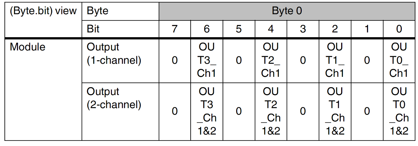
Safe digital inputs
- For 2-channel assignment: four 2-channel inputs
- For 1-channel assignment: eight 1-channel inputs
Safe digital outputs
- For 2-channel assignment: 4 two-channel outputs
- For 1-channel assignment: 4 1-channel outputs
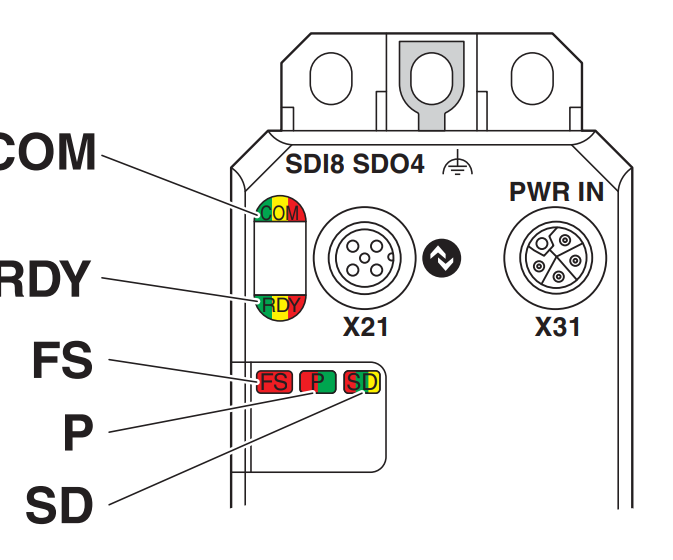
LED
Please refer to the instruction manual for details.
- COM=IO-LINK communication status
- RDY=Module power supply status
- FS=Fail safety status of the module
- P=Safety communication state
- SD=Diagnostic status of safety application
Safe state
From the module’s perspective, a safe state is;
- Send Process Input data to the safe controller to 0
- No-voltage state of output
Why?
The safety state transitions in the following cases:
Operating state
With the module in normal operation, the input/output will be in the state “1” or “0”. By the way, state “0” is a safe state.
Error detection in I/O devices
Error detection is divided into input and output.
Inputs
If an error is detected on an input, that input is switched to the safe state (i.e., False).
Outputs
If an error is detected on an output, this output is placed in an invalid safe state (i.e., False).
What kind of Error?
The following errors can be detected by setting the module parameters.
- Input/output shorts and cross circuits
- Output overloads
- Overloads or short circuits on clock outputs
Device Error
It depends on the operation time in error. It is important to note that in an error condition, internal module tests will no longer be performed and the safe state may be terminated depending on the accumulation time of the error.
(If a module enters an error condition, it must be evaluated, approved, or cleared of errors within 72 hours.)
Serious errors
Critical errors that result in loss or adverse effect on safety functions occur in the following cases;
- The entire module enters a safe state.
- The FS LED of the module is always lit.
It depends on the operation time in error. It is important to note that in an error condition, internal module tests will no longer be performed and the safe state may be terminated depending on the accumulation time of the error.
(If a module enters an error condition, it must be evaluated, approved, or cleared of errors within 72 hours.)
Parameterization errors
This is the case when a parameter is set that is not accepted by the module.
Safety-related system time
Input
The processing time tIN of the input at the time of the safety request is the sum of the parameter filter time tFilter and the firmware processing time tFW.

Output
The shutdown time of output tOUT on safety request is the sum of the internal processing time of 3.5 ms and the parameter switch-off delay time tdelay.

Process data words
Input

Output
Function Block
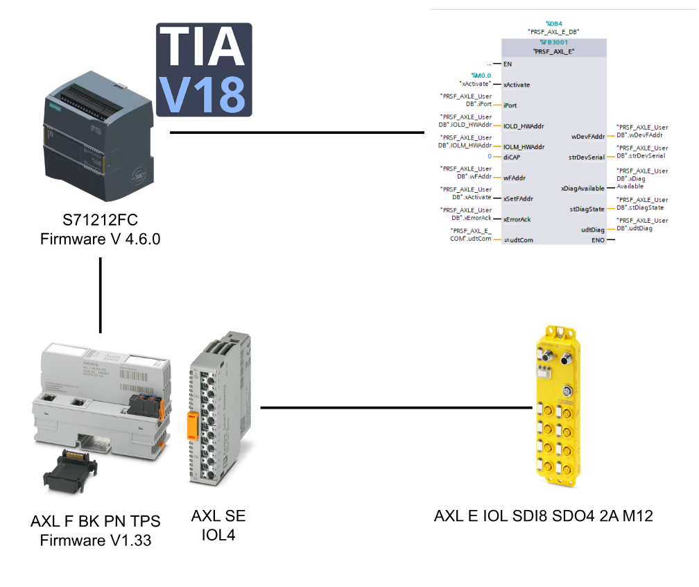
PRSF_AXL_E
This Function Block sets a new F-Address for the AXL E IOL PROFIsafe module and can collect diagnostic information if an error occurs in the connected module.
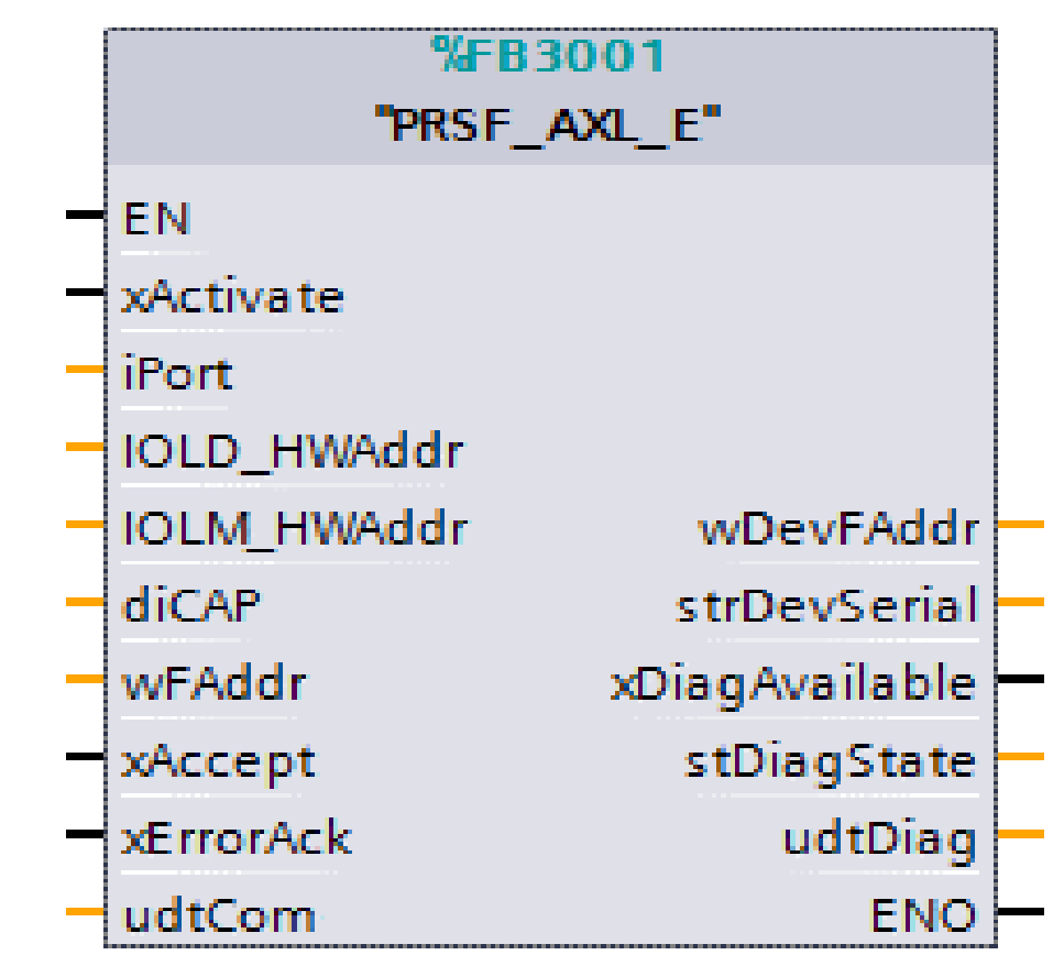
VAR_INPUT
| Variable Name | Type | Descritpion |
| xActivate | BOOL | True=Enable Function Block |
| iPort | INT | Port number of IO Link Master |
| IOLD_HWAddr | HW_ANY | Hardware-identifier of the module (explained later) |
| IOLM_HWAddr | HW_ANY | IHardware-identifier for O-Link Master (explained later) |
| diCAP | DINT | Client Access Point(Set to 0 for AXL F IOL8 2H and AXL SE IOL4 i) |
| wFAddr | WORD | Writes to IO-Link device Profisafe F Address |
| xAccept | BOOL | Write Profisafe F Address to Profisafe IO-Link device with a rising edge |
| xErrorAck | BOOL | Clear diagnostic messages pending with a rising edge |
VAR_OUTPUT
| Variable Name | Type | Descritpion |
| wDevFAddr | WORD | Current F Address of the connected module |
| strDevSerial | STRING | Serial number of the connected module |
| xDiagAvailable | BOOL | True= Diagnostic information available |
| stDiagState | Structure | Detailed diagnostic data on FB |
| stDiagState.iLfd | UINT | Fault number |
| stDiagState.iPrio | UINT | Failure Priority |
| stDiagState.bChannel | BYTE | Channel |
| stDiagState.wCode | WORD | Error Code |
| stDiagState.FunctionGroup | STRING[8] | Function Group for diagnostic information |
| stDiagState.dwAddValue | DWORD | Error codes for detailed diagnostic information |
| stDiagState.TextLength | UINT | Bytes of diagnostic text |
| stDiagState.Text | STRING[100] | diagnostic text |
| udtDiag | UDT | Stores diagnostic data of FB itself |
| udtDiag.wDiagCode | WORD | Diagnostic data code of the FB itself |
| udtDiag.wAddDiagCode | WORD | Additional Diagnostic Information for wDiagCode |
| udtDiag.xError | BOOL | 1=FB internal error |
| udtDiag.iState | INT | Current internal state of FB |
| udtDiag.IOL_CallDiag | PRSF_UDT_IOCALL | IO_LINK_DEVICE Information about input/output is stored. |
VAR_INOUT
| Variable Name | Type | Descritpion |
| udtCom | UDT | Information about Profinet alarms is stored (hardware addresses and communication management of IO-LINK devices) |
| udtCom.arr_i_Com Array | Array [0..255] of UINT | Storage location of hardware addresses of modules with pending communication requests |
| udtCom.arr_HW | Array [0..8] ofHW_ANY | Storage place for hardware addresses of connected modules, where each element represents a connected port of the IO-Link master |
| udtCom.arr_HW_Diag | Array [0..8] of Bool | Storage location for information about Profinet alarms recognized on a particular port |
Error
| DiagCode | Description |
| 0000hex | FB inactive |
| 8000hex | Wait for command or alarm event while FB is in effect |
| 8100hex | FB initialization in progress |
| 8200hex | FB is writing a new F Address |
| 8300hex | FB is loading diagnostic information |
| 8300hex | FB Acks diagnostic information |
| C301hex | Multiple communication errors, need to check HW-Address and wiring |
Implementation
The S71212FC/AXL F BK PN TPS and AXL SE IOL4 will be used to integrate AXL E IOL SDI8 SDO4 2A M12 into the application.
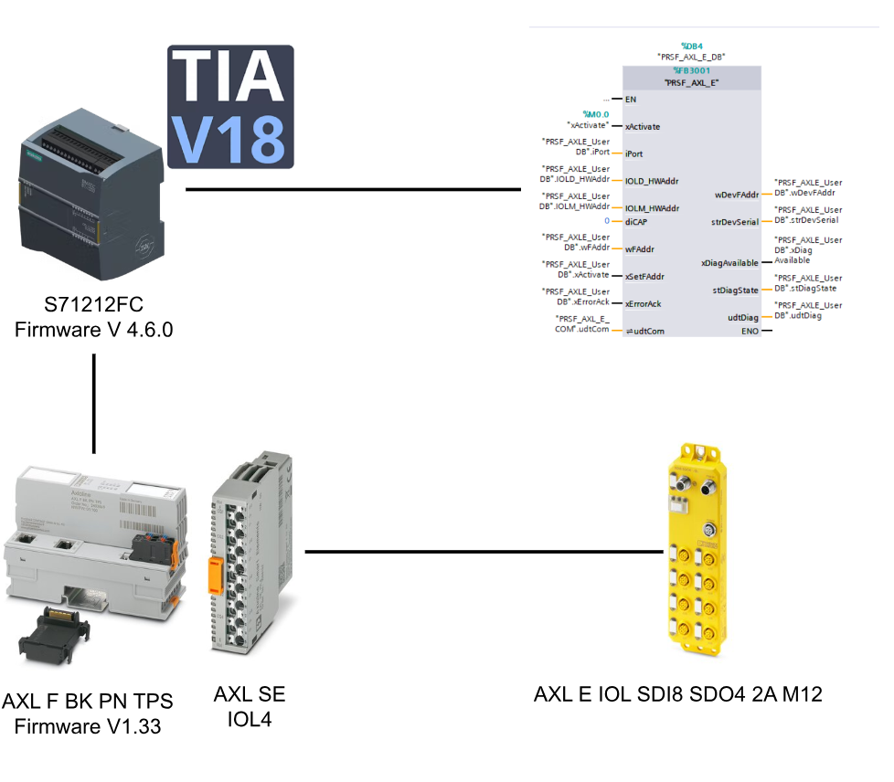
Siemens Side
Add New Project
Start TIA and create a new project with New Project.
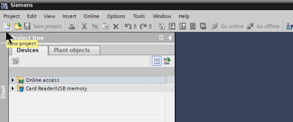
Enter a Project Name and click “Create” to proceed.
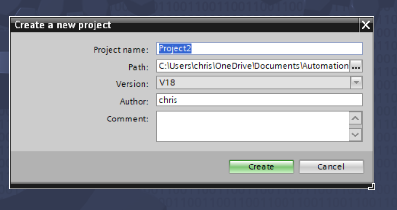
Done! A new PLC has been added.

Add New PLC
Next, click Add New Device to add S71212FC.

Select CPU1212FC to be used in this article and add a CPU with >Ok.
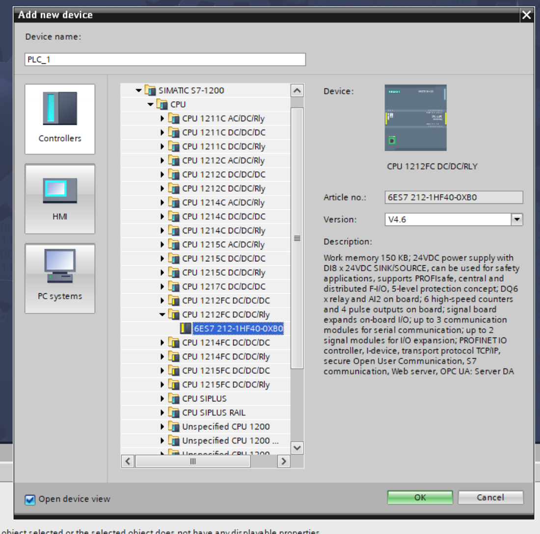
Done!S71212FC has been added.

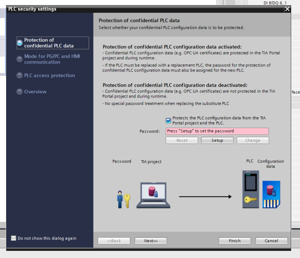
Security Settings
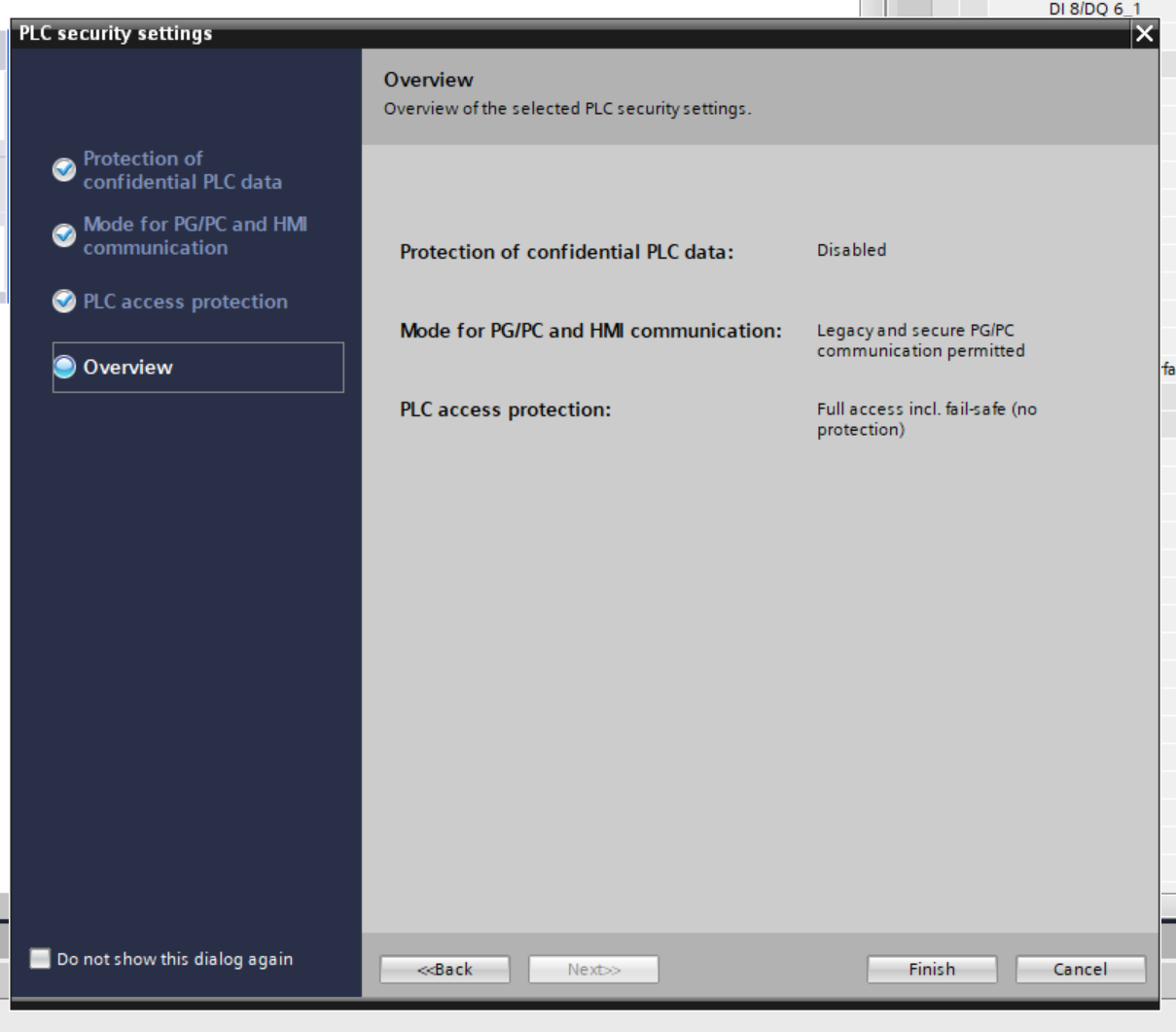
TIA will automatically display the security configuration screen for the CPU.
If you do not need a password, uncheck the “Protects the PLC Configuration data from the TIA Portal project and the PLC” checkbox and press Next>> to proceed.
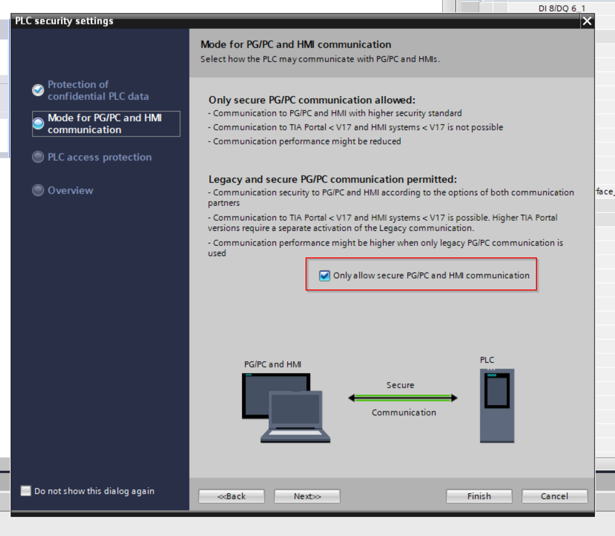
If you do not want to limit the devices that can access the S71200, uncheck “Only allow securce PG/PC and HMI Communication” and press Next>> to proceed.
Set access privileges without password and proceed with Next>>.
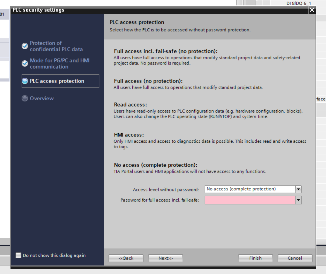
Done!
Change PLC IP
Click on Devices & Networks to change the IP address of S71212 and switch to Network View.

Click on the Show address labels button.

The IP address of each device is displayed, click directly on it to change the IP.

Install GSDML
Next, download the PROFINET Coupler GSDML File for AXL F BK PN TPS from the link below.
https://www.phoenixcontact.com/en-pc/products/bus-coupler-axl-f-bk-pn-tps-2403869
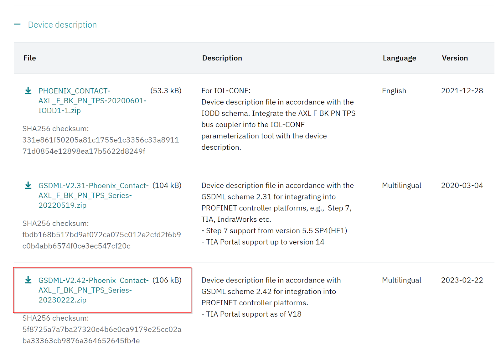
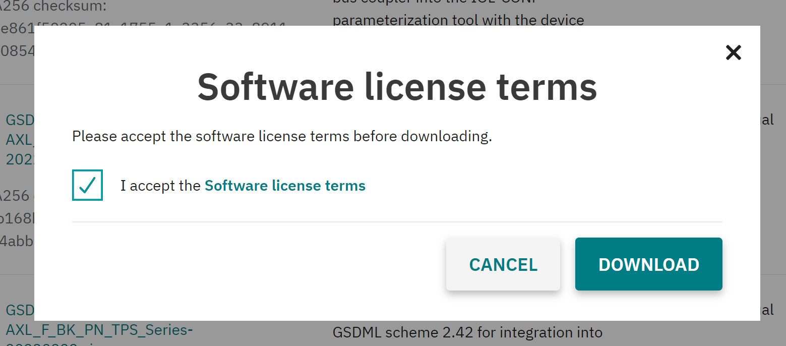
Agree to the license and download.
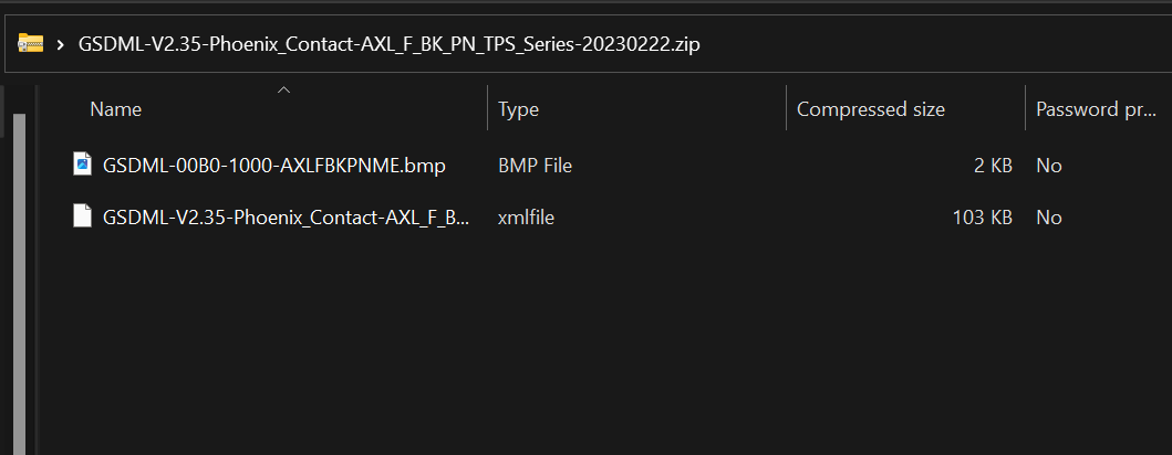
A ZIP file like this was downloaded.

Unzip the Zip.
Install the GSDML File in TIA.
Click Options>Manage general station description file (GSD).
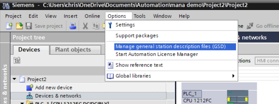
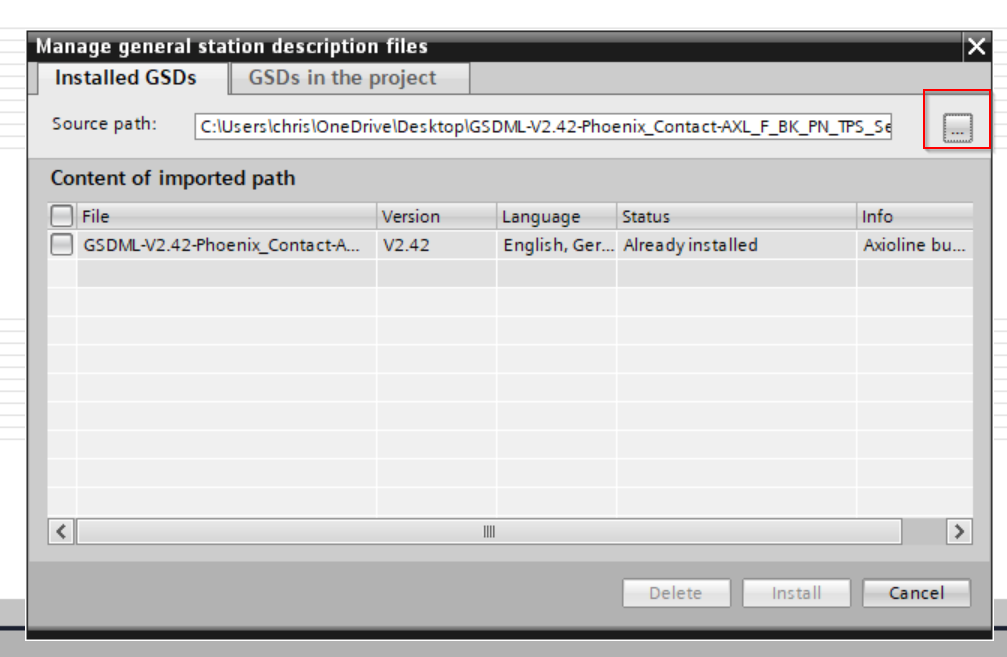
The GSD File installation screen will appear.

Click on the button “…”.
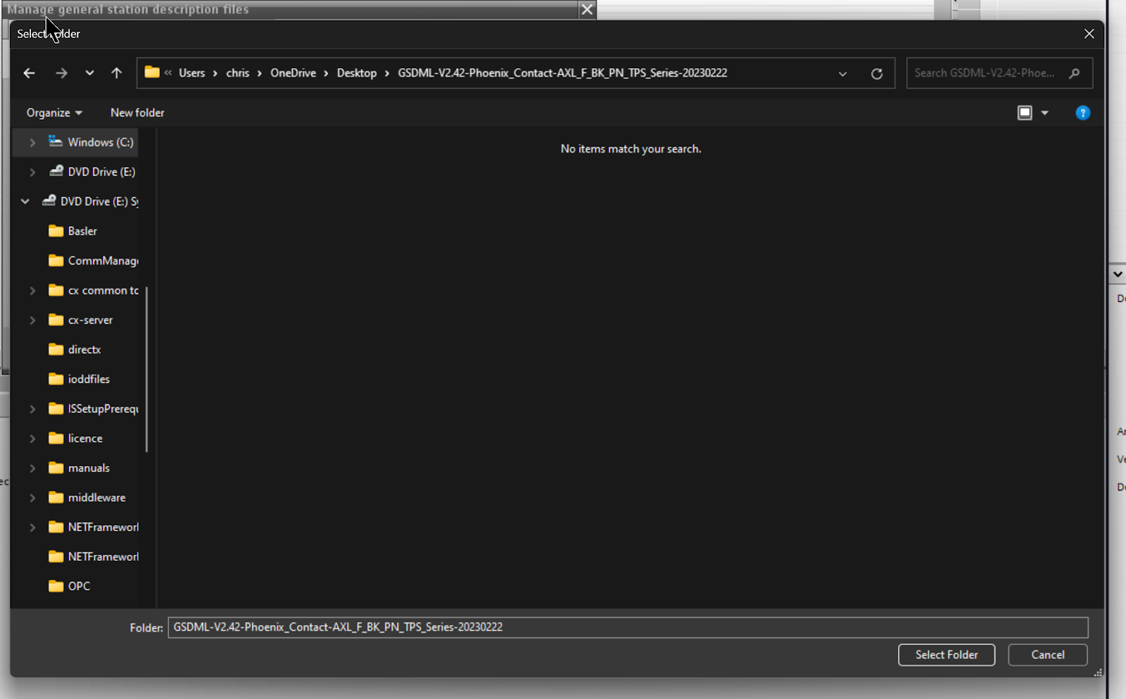
Select the GSDML file downloaded from Phoenix Contact HP.
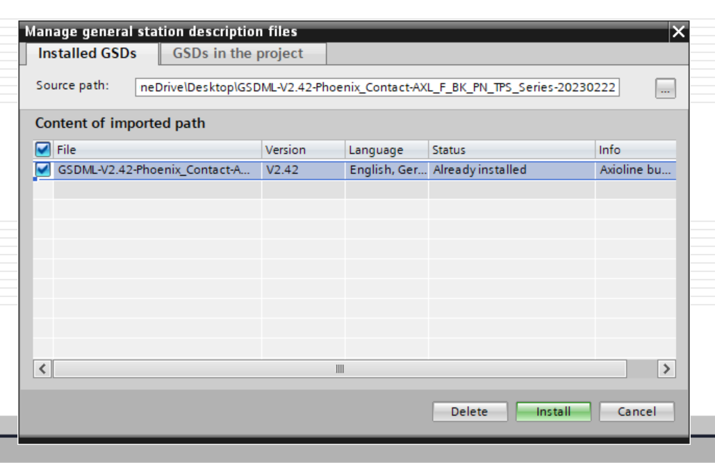
Select GSDML File > Install to install the GSDML File in TIA.
Configure Coupler
The next step is to build a PROFINET network.
Add New
Add the Phoenix Contact PROFINET coupler from AXL F BK PN TPS from the Hardware catalog to your network.
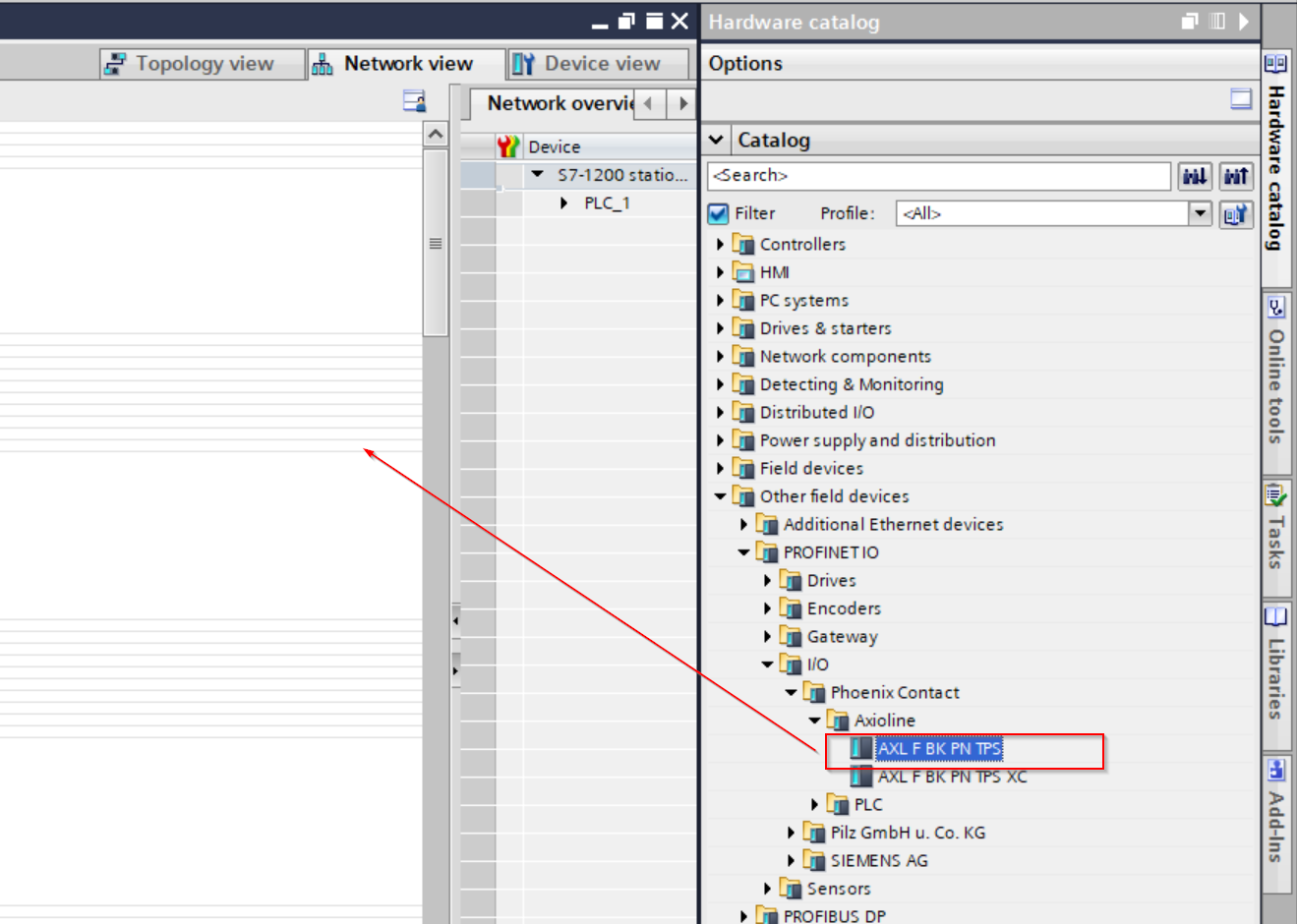
You can change another version of GSDML from the Version Field in Information.

Done!
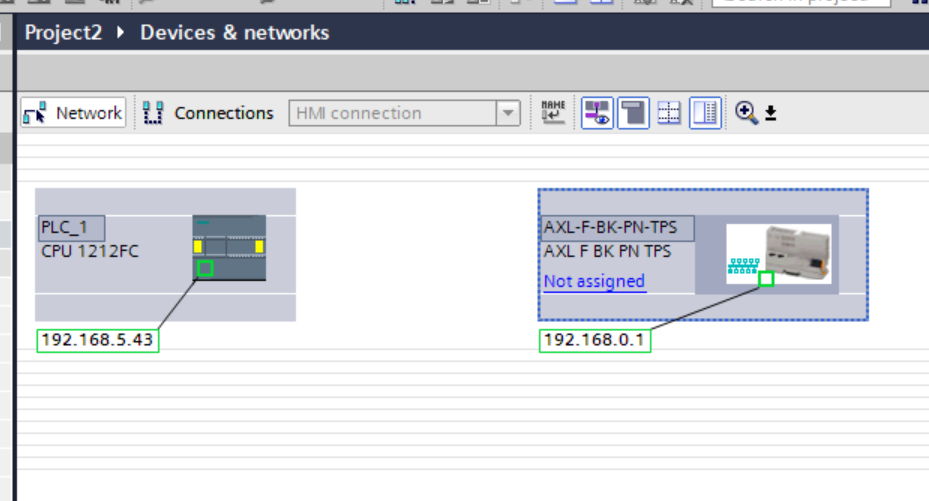
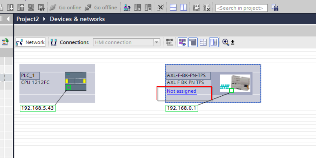
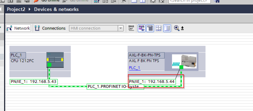
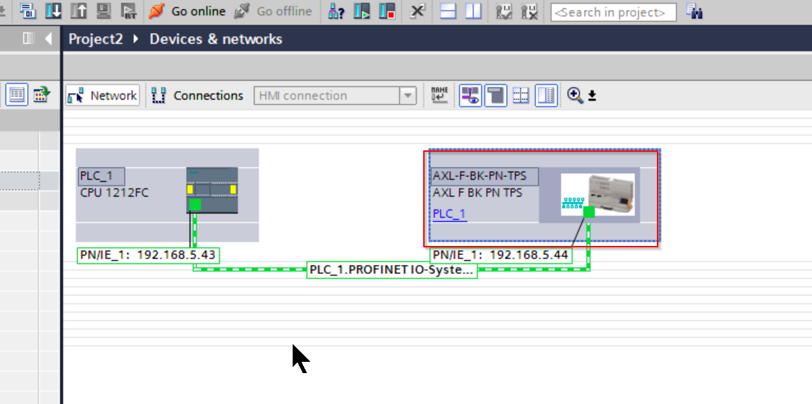
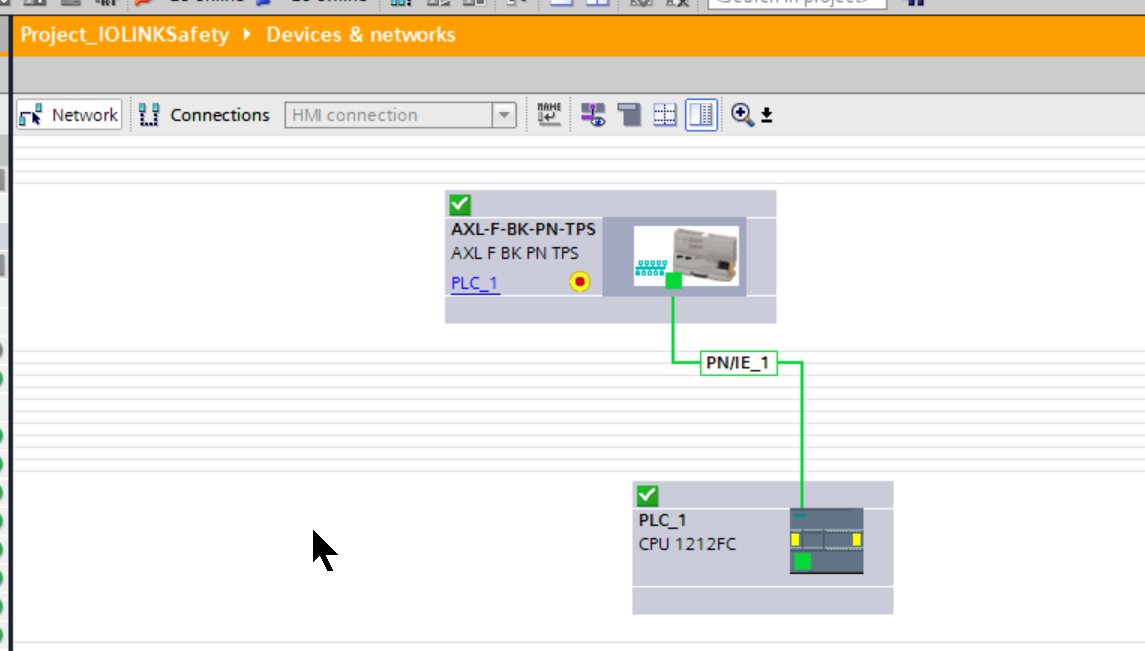
Connect to Profinet Network
Click on Not assigned to configure the AXL F BK PN TPS in Phoenix Contact for PROFINET connection to the S71200.
Done!S71200 and AXL F BK PN TPS connected via PROFINET.
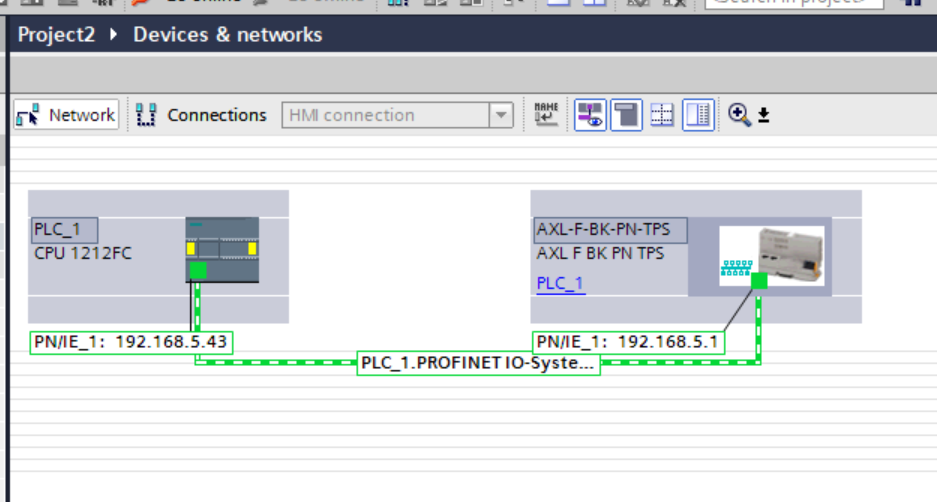
Change IP
Set the IP address according to the actual application.
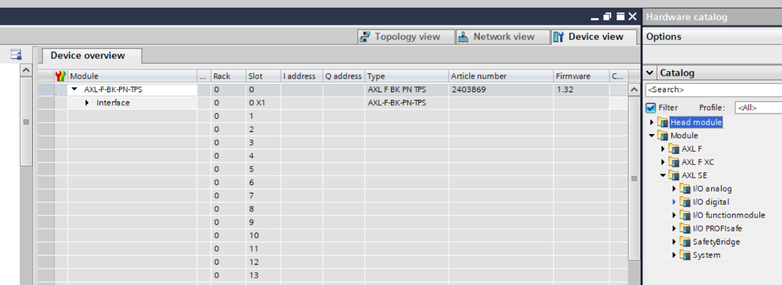
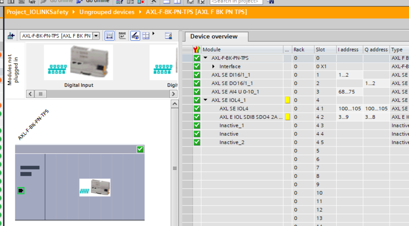
Add Slot
The next step is to build a Slot for the AXL F BK PN TPS PROFINET coupler.
TIA switches to Device view.

Smart Elements can be added to each coupler slot from AXL SE’s Catalog.
Add AOL4
One of the main actors used in this article AXL SE IOL4 is added to Slot.
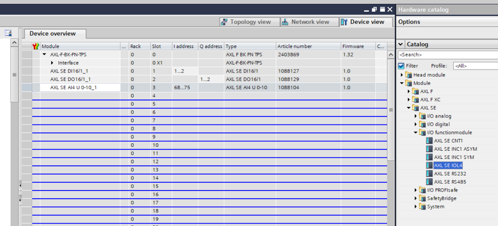
Done!
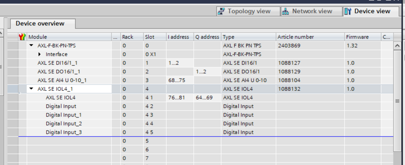
Configure SubSlot
Now edit the Subslot of AXL SE IOL4: AXL E IOL SDI8 SDO4 2A M12 L is installed in Port1 of AXL SE IOL4, so edit the second SubSlot.

Delete the second SubSlot.

Next, let’s add AXL E IOL SDI8 SDO4 2A M12 L from Catalog>Submodules>Phoenix Contact>IOL PROFIsafe.
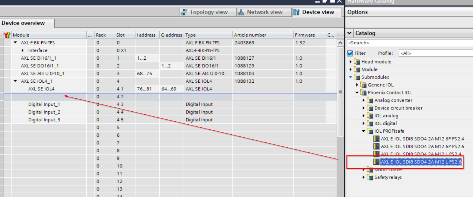
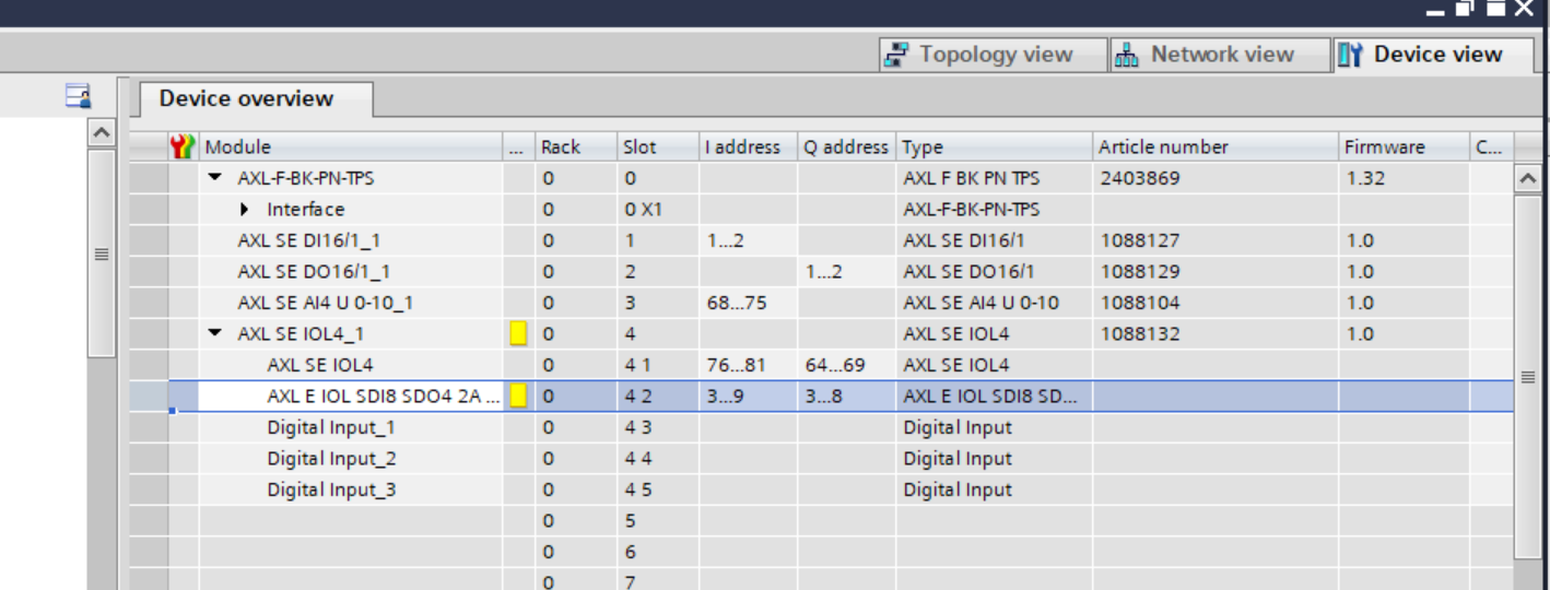
Done!

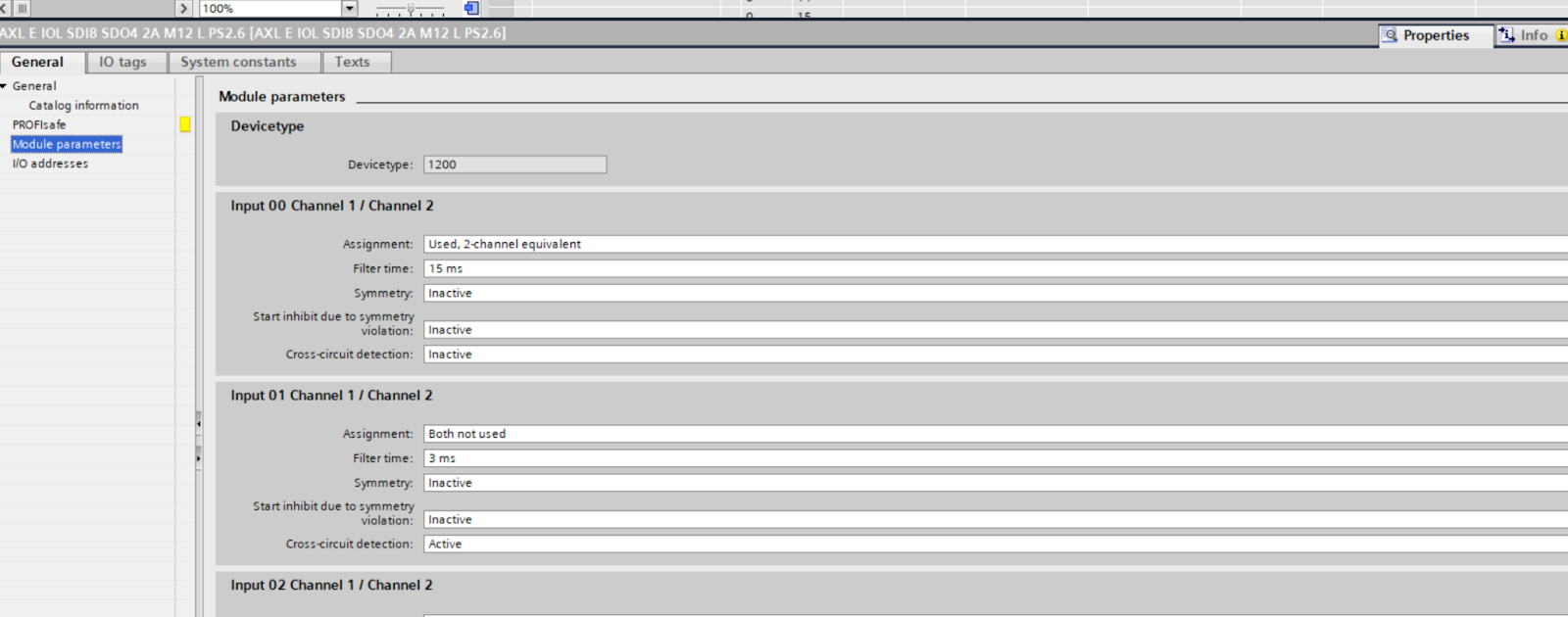
Module Parameters
Please configure each Port according to the actual application engineer.
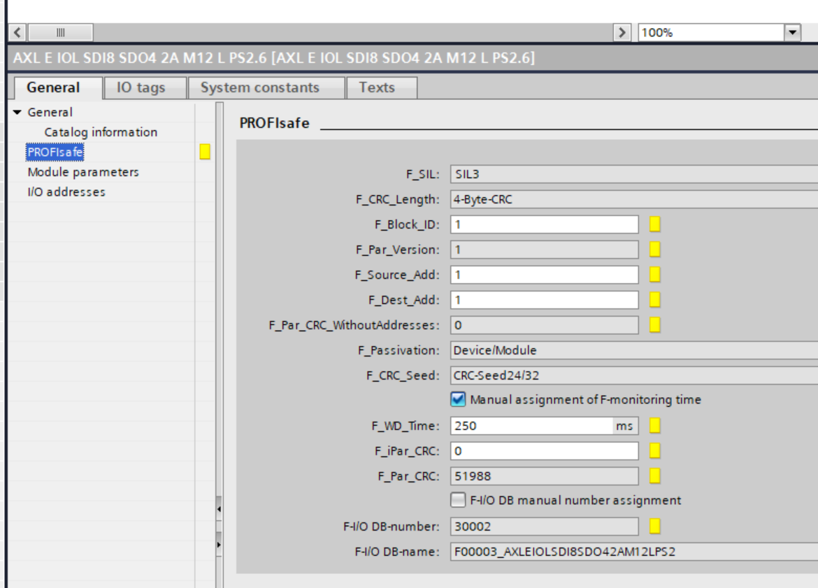
Profisafe Parameters
Sets the PROFIsafe parameter for AXL E IOL SDI8 SDO4 2A M12 L.
The PROFIsafe setup screen will appear, and it is OK if you set F_Dest_Add and F_iPar_CRC.
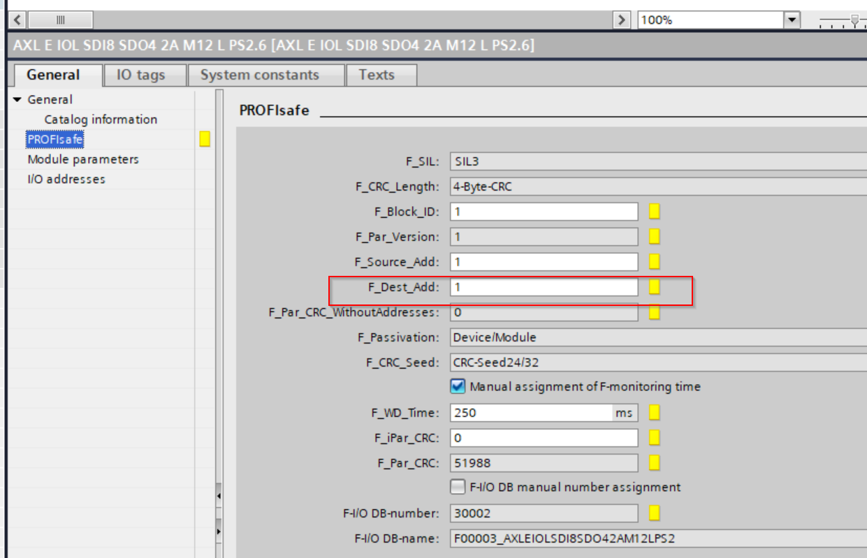
F_Dest_Add
F_Dest_Add is OK as long as it does not overlap with the same PROFIsafe network. In this case, set F_Dest_Add=9.
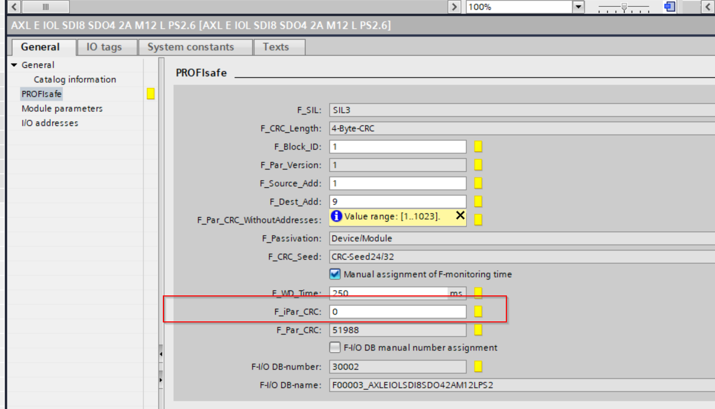
F_iParCRC
The next step is to set F_iParCRC. The F_iParCRC is the CRC value used to verify that the parameters of the corresponding Safety module have not been modified.
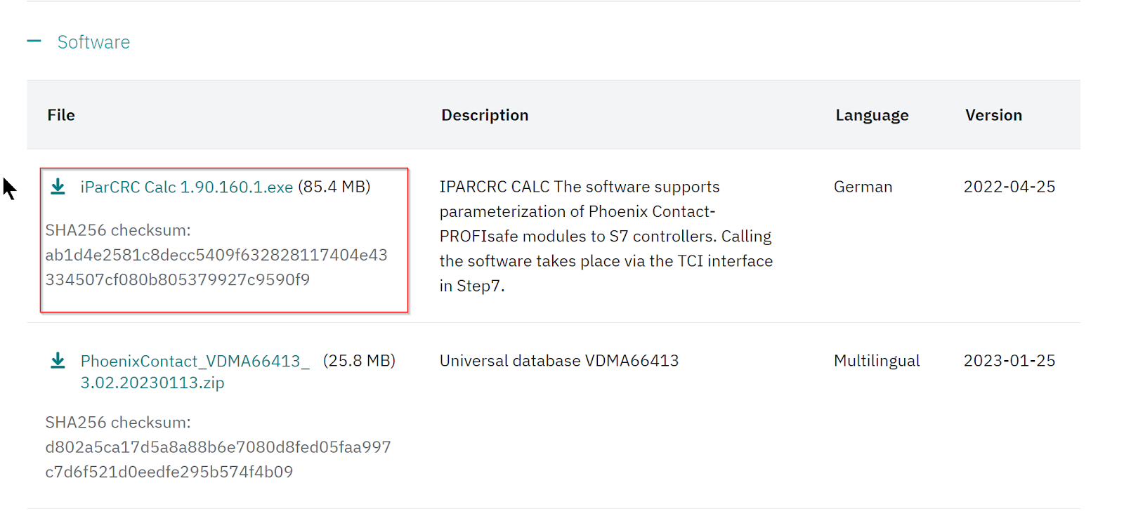
Installation Tools
Download the CRC calculation tool from Phoenix Contact HP to calculate the iParCRC value.
https://www.phoenixcontact.com/en-pc/products/safety-module-axl-e-iol-sdi8-sdo4-2a-m12-l-1185380
Start the Installation File, select the language and press >Ok to proceed.

Just a second…

Proceed with Next.

Accept the license and proceed with Next.

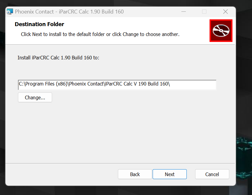
Set the Installation Location and press Next to proceed.
Click the Install button to proceed.

Just a second..
Done!

Get CRC
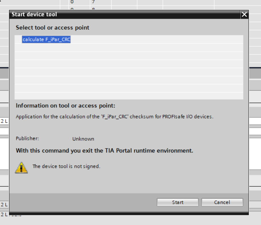
Right click on AXL E IOL SDI8 SDO4 2A M12 L > Start device tool to launch the iCRC calculation tool you just installed.

Start to launch the tool.
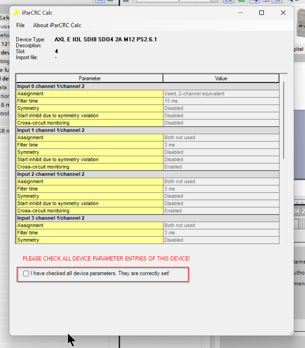
Now that the safety parameters set for AXL E IOL SDI8 SDO4 2A M12 L are displayed, let’s double-check that they are correct.
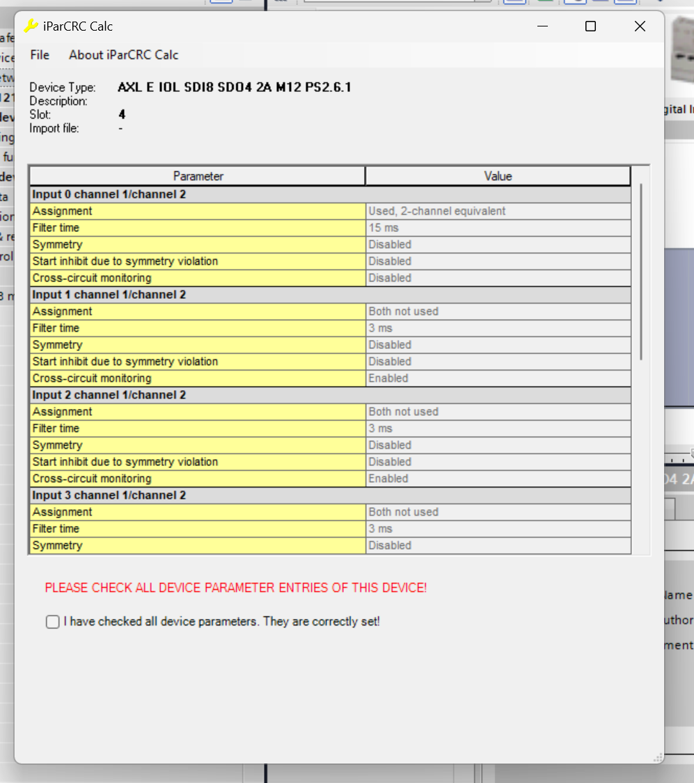
Please check the “I have checked all device parameters They are correctly set!” ‘s Checkbox.
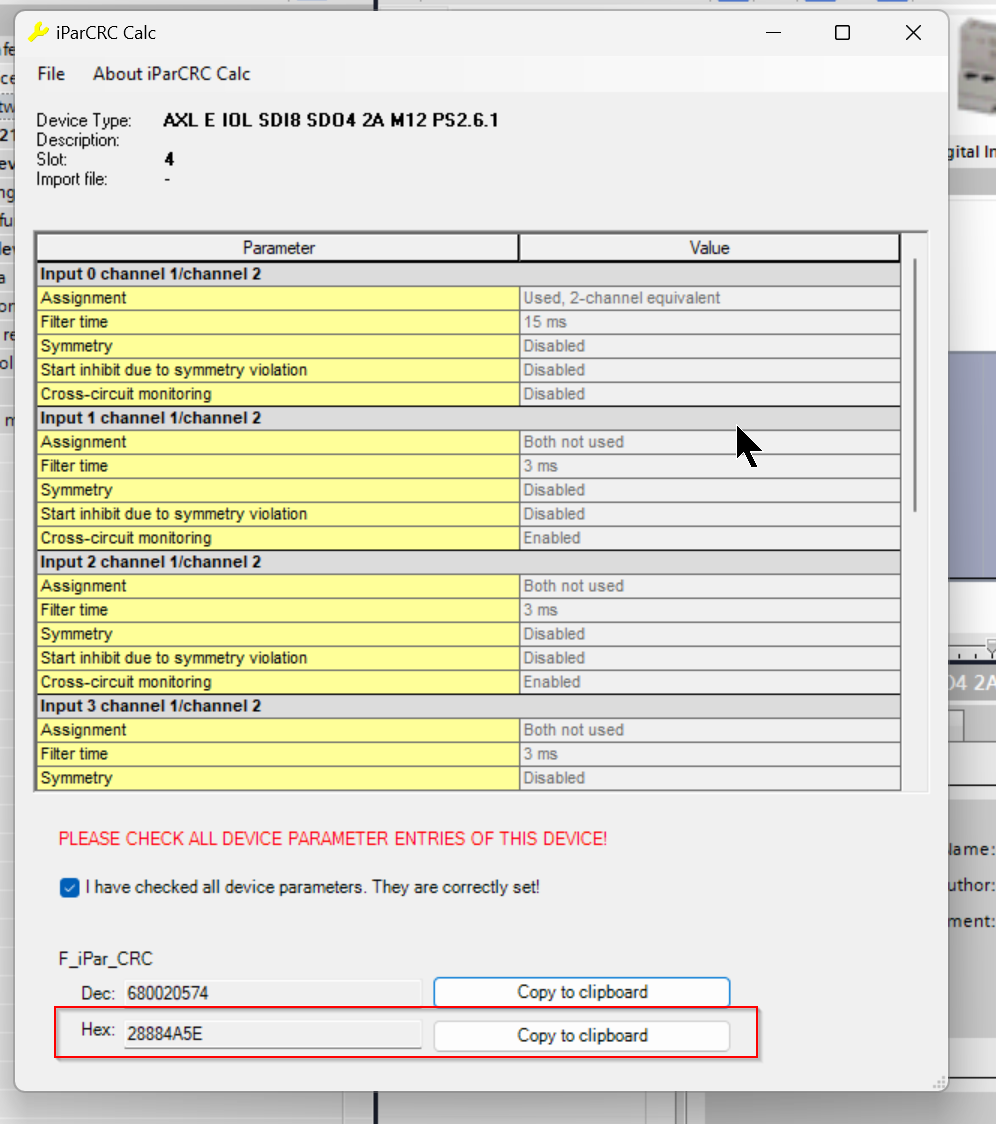
The Hex and Dec values of F_iPar_CRC are displayed.
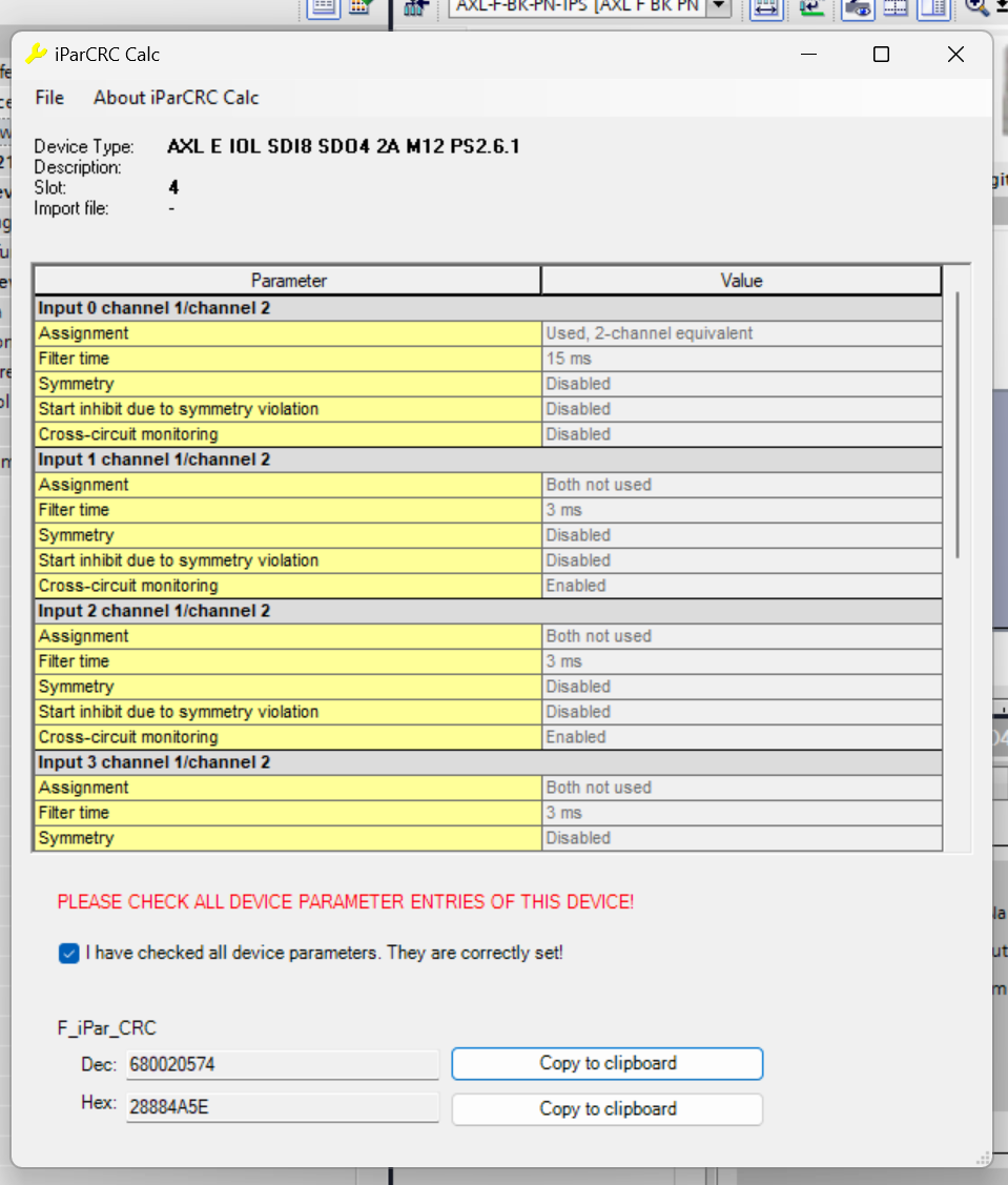
Since TIA requires the input of hex values, click “Copy to clipboard” next to the hex value and copy the hex value.
Fill in CRC
Paste the CRC value you just copied into the Field of F_iPar_CRC.

Program
The next step is to create a write program for F-Address.
Download library
Download the AXL E IOL SDI8 SDO4 2A M12 L library from the Phoenix Contact website.
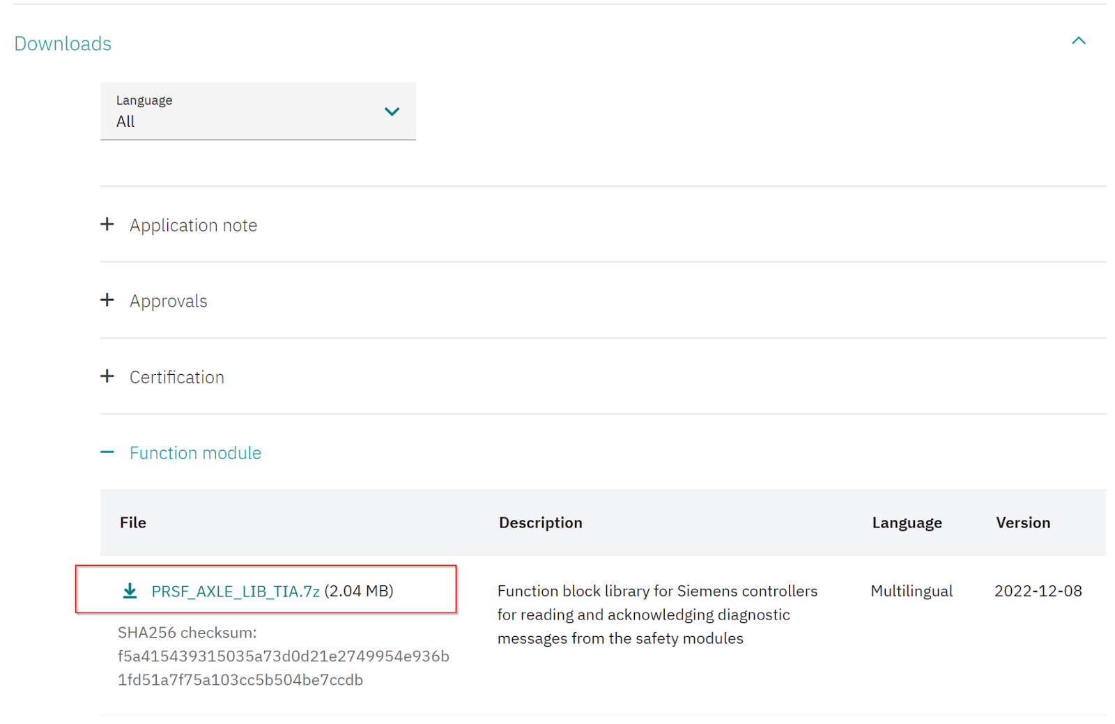
Agree to the license and download the library.

7z File has been Downloaded.

Unzip the library.
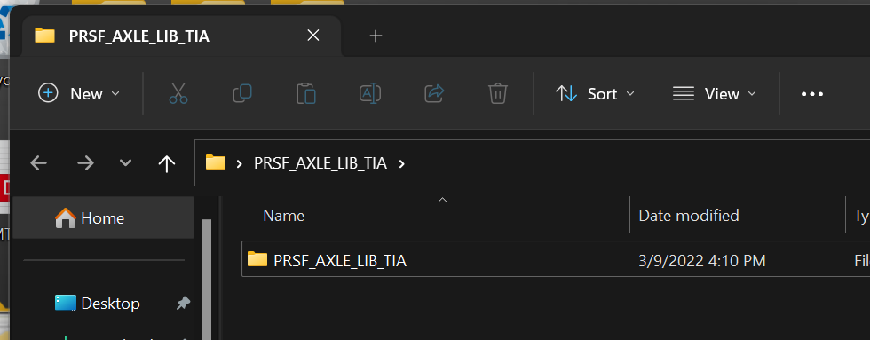
Add Library
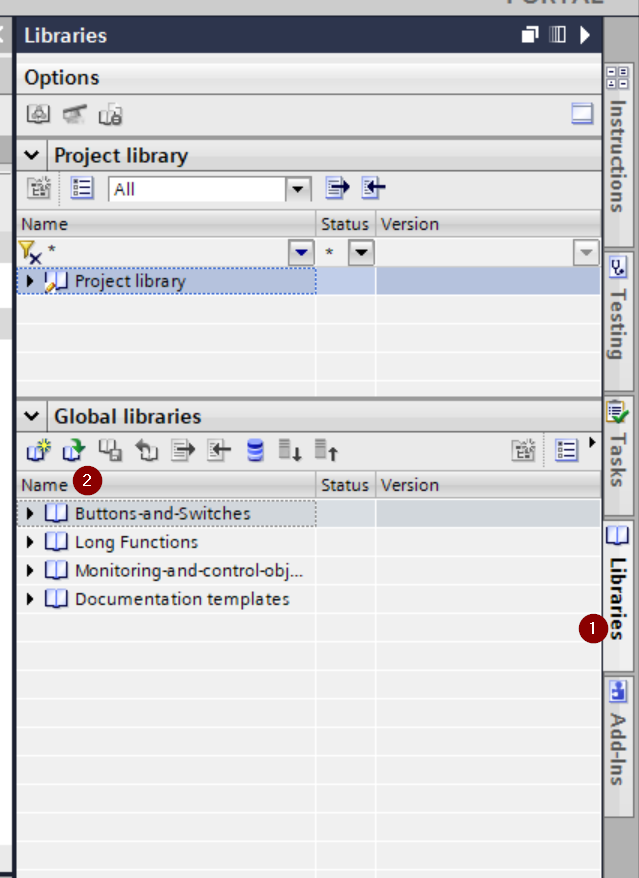
To import libraries downloaded from Phoenix Contact in TIA, go to Libaries>Global libraries>Open library.
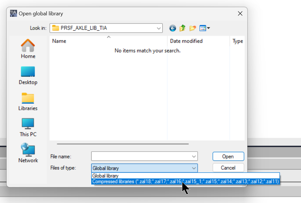
On the Open global library screen, select Compressed library for File of Type.
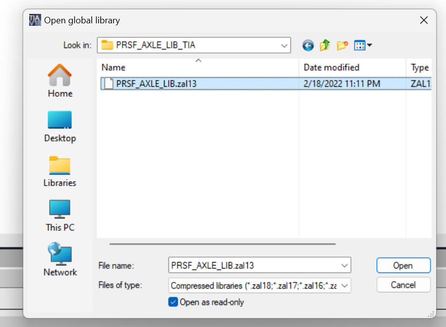
Select zal13>Open.
Set the decompression location for the library.

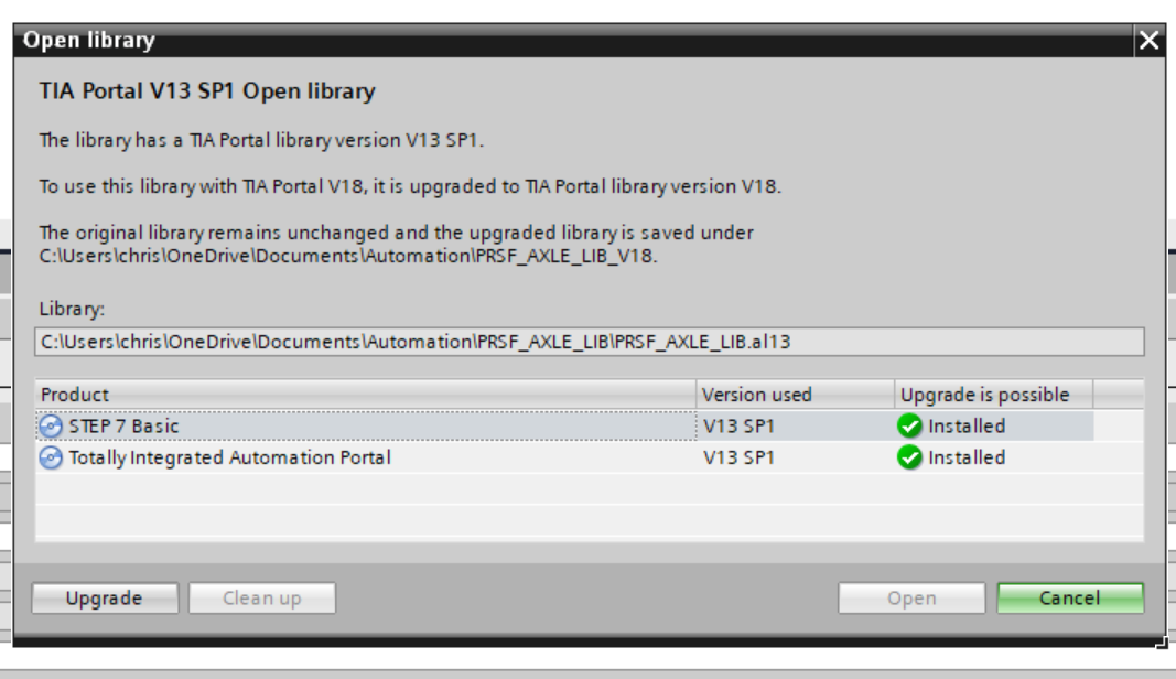
Since zal13 was created from TIA V13 SP1 and now I have TIA V18, I need to upgrade the library and click on Upgrade.
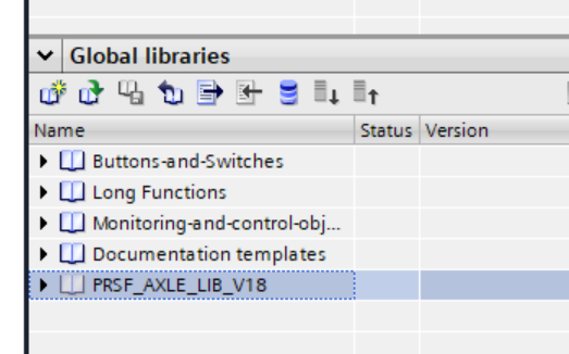
Done!The library has been imported.
Import to Project
Add the master copies in the library to your project.
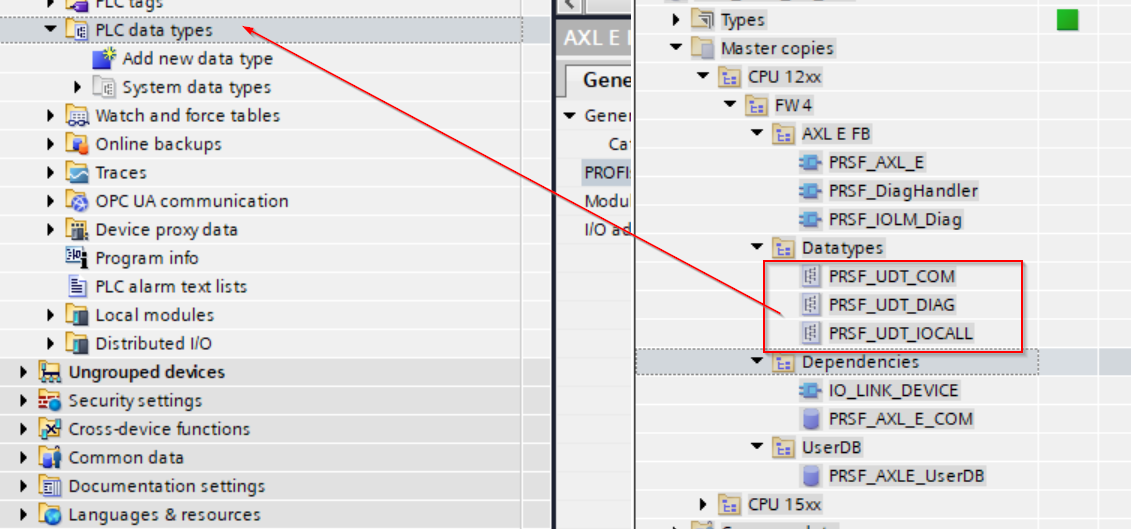
First, add Datatypes to the PLC data types Folder.
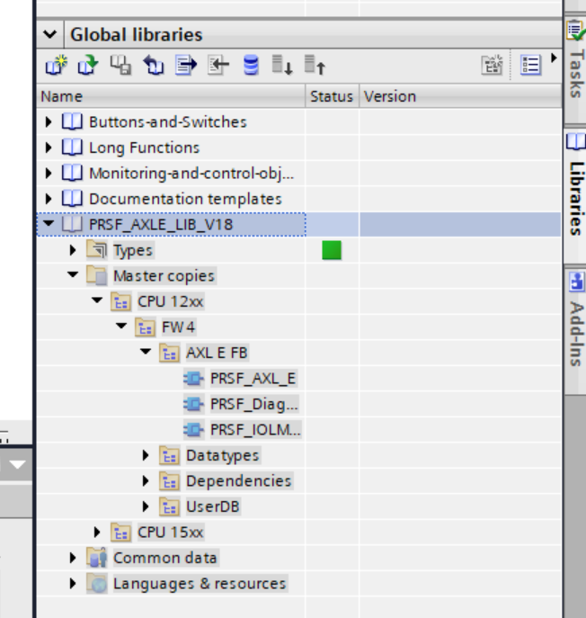
Next, let’s add the AXL E FB, Dependencies and UserDB Folder in your Project.
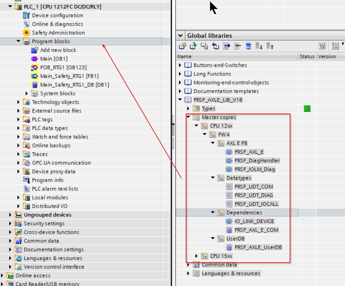
Done!Library has been added.
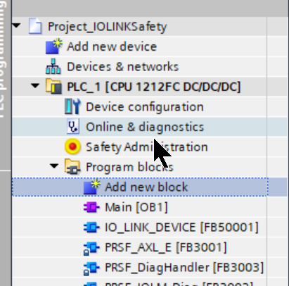
Add OB30
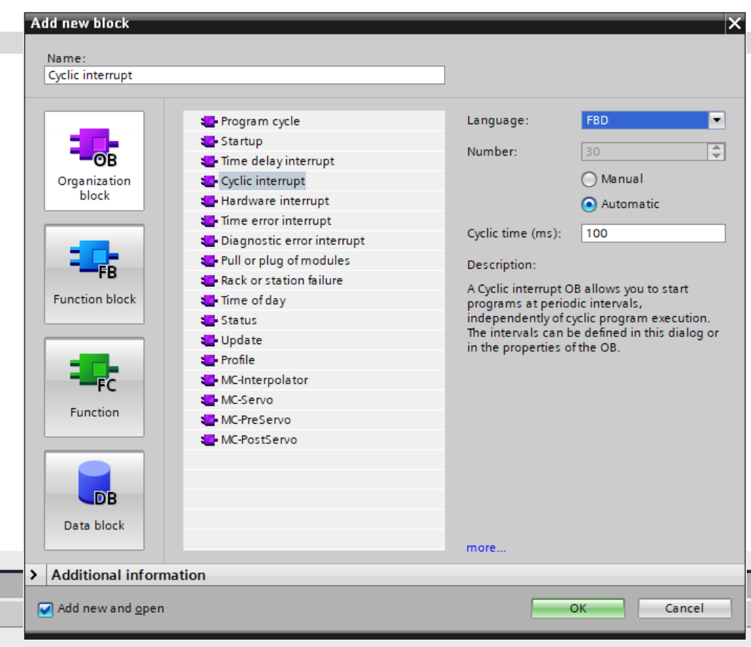
Add a fixed-cycle OB with Program Blocks >Add New block.
Choose OB>Cyclic interrupt and Cyclical time (ms) to 100 (i.e., it will run at a fixed cycle of 100 ms).
Next, open OB30.
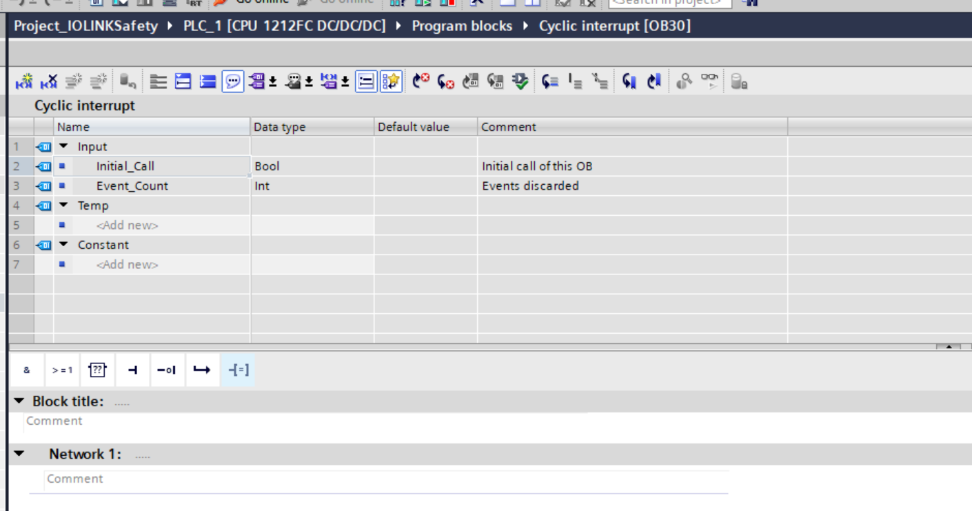
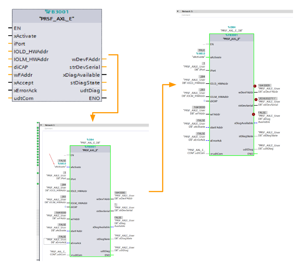
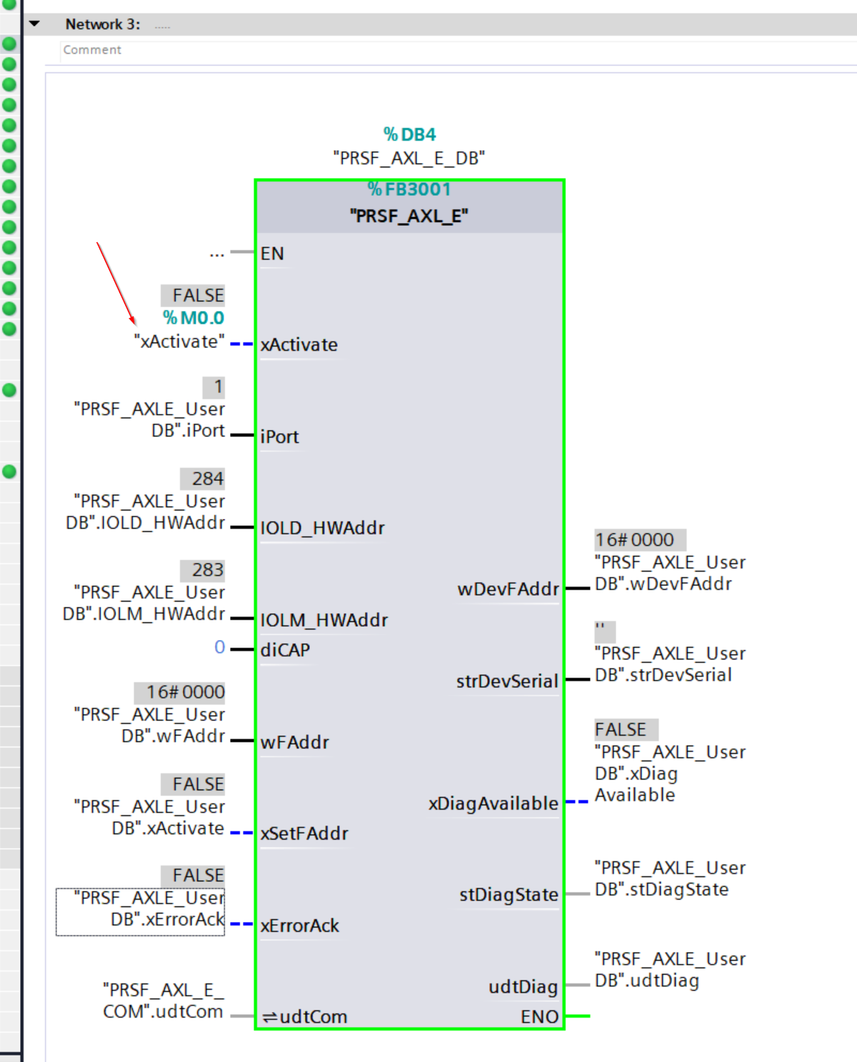
Add the FB PRSF_AXL_E added earlier.

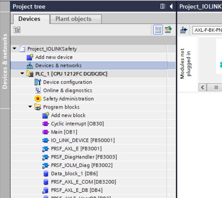
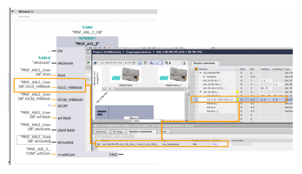
IOLD_HWAddr
The IOLD_HWAddr value should be referenced as shown in the figure below.
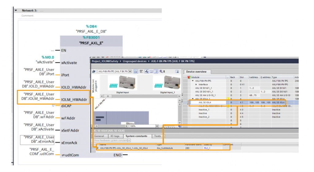
IOLM_HWAddr
The IOLM_HWAddr value should be referenced as shown in the figure below.
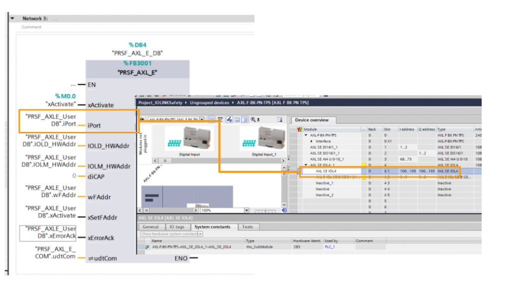
Port
The Port number should match the Port number connected to the actual AXL E IOL SDI8 SDO4 2A M12 L module.
Safety Program
AXL E IOL SDI8 SDO4 2A M12 L is a PROFIsafe module, so create a safety program in Main_Safety_RTG1.

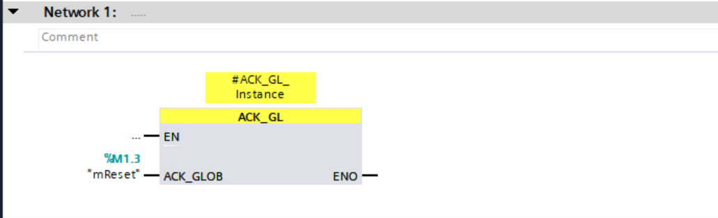
Network1
Add Function Block ACK_GL to recover the status of the device from Fail-Safe state.
Network2
Configure the AXL E IOL SDI8 SDO4 2A M12 that can be recovered without ACK from Fail Safe state.

Network3
Add Safety Function Block ESTOP1 and Link it to the Emergency Stop Safety Input connected to the Port of AXL E IOL SDI8 SDO4 2A M12 and tie the Safety Output to the Emergency Stop LAMP.

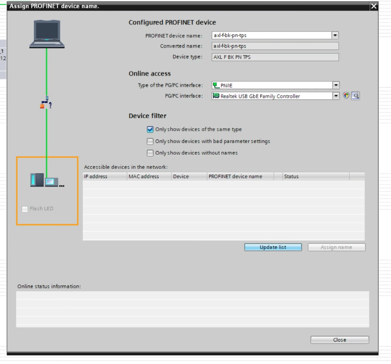
Assign Devices Name
Since this is a PROFINET communication, do not forget to set the device name of the AXL FBK PN TPS PROFINET coupler: right-click on AXL FBK PN TPS > Assign device Name.

Select PG/PC Interface > Search for the device in the Update List and assign the device name from the Assign name button.
Download
The last step is to download the project to the CPU.

Result
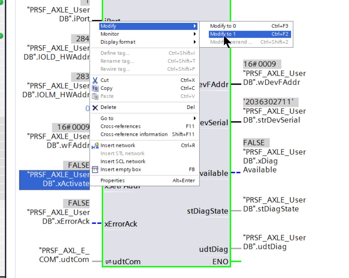
Set F_Dest_Add
Initially set xActivate to True to set the F-Address for AXL E IOL SDI8 SDO4 2A M12.
If the Function Block and AXL E IOL SDI8 SDO4 2A M12 are in successful communication, the F-Address and serial number of the current AXL E IOL SDI8 SDO4 2A M12 and diagnostic information are returned.
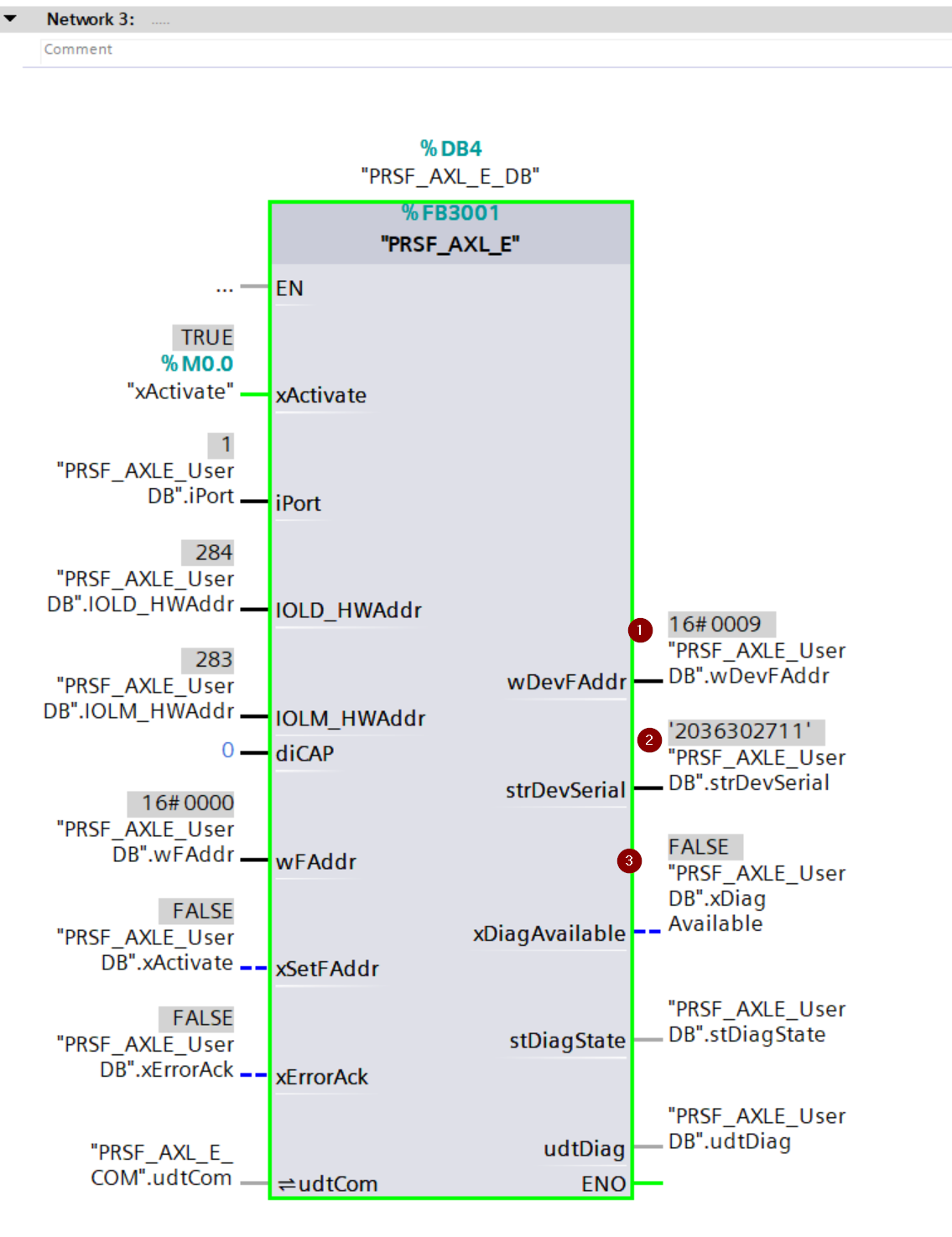
Next, xSetFAddr is set to True and F_Dest_Addr is written.
View in TIA
No PROFINET network errors from TIA’s Network View either.
Each slot is recognized and error-free!
LED Status
This is the LED Status of AXL E IOL SDI8 SDO4 2A M12 L when normal.
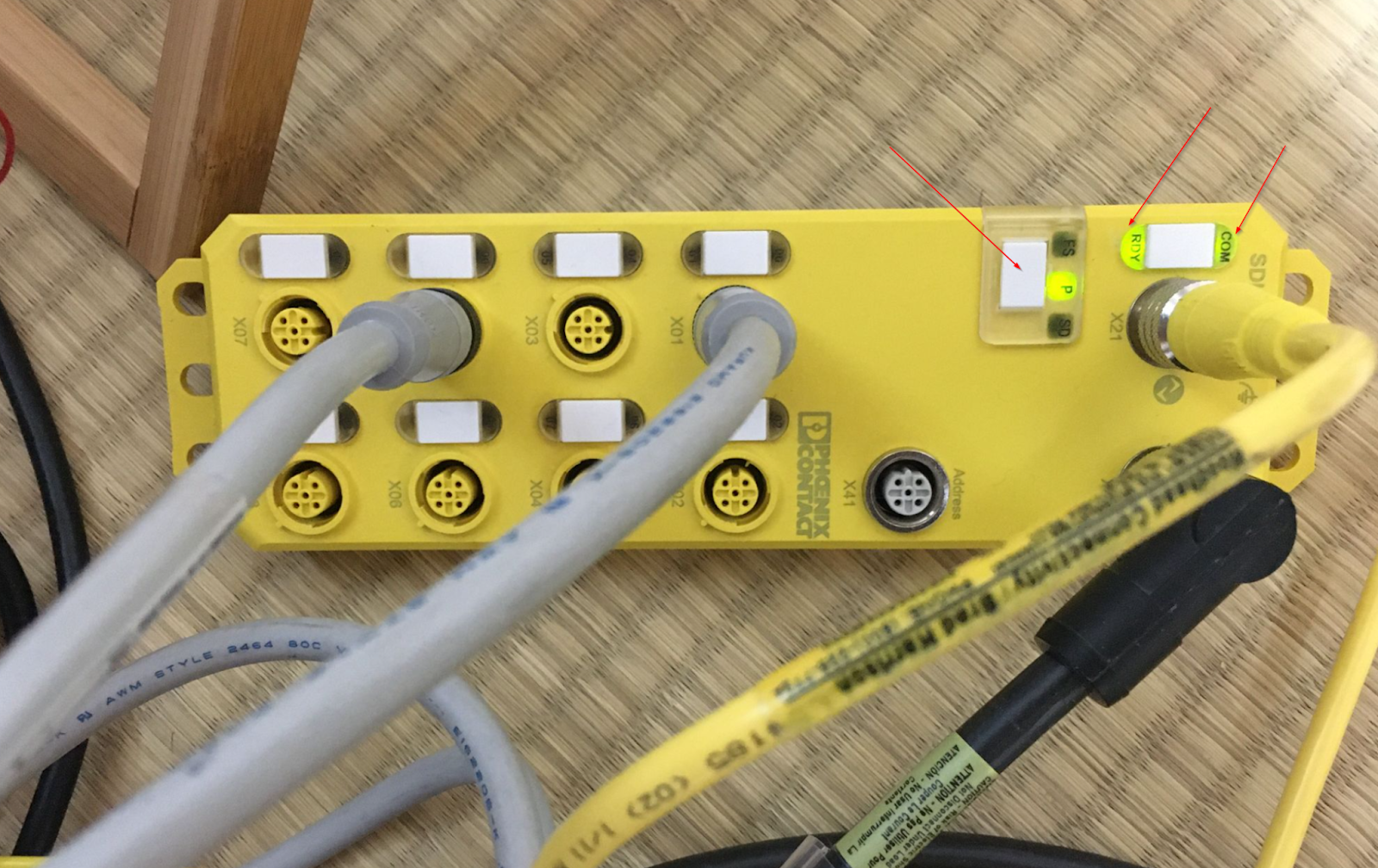
You can also check it out in this video.
Operation
You can check the actual operation from the following Link.
Download Project
Download the project from this link.
https://github.com/soup01Threes/Siemens/blob/main/Project_IOLINKSafety.zap18