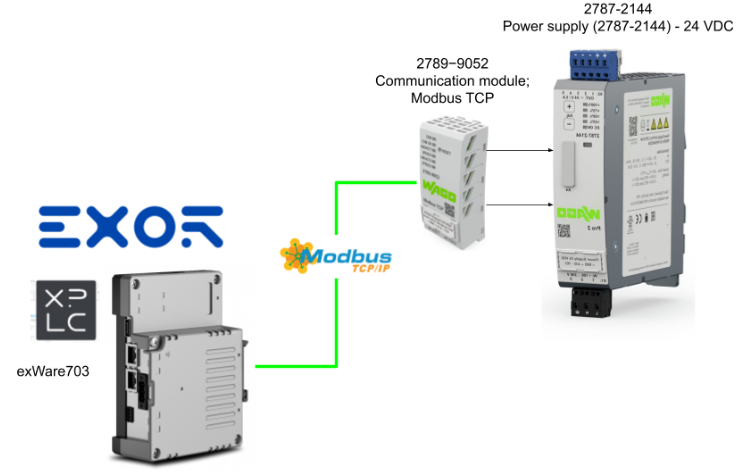
This is a new series of articles, in which EXOR’s XPLC is used to perform and transmit various verifications.In the second article, we will show you how to build a Modbus TCP Master, and the Modbus TCP Slave will be WAGO’s communication module 2789-9052.
Come on, let’s enjoy FA.
Foreword
Thank you from the bottom of my heart for visiting my technical blog and YouTube channel.
We are currently running the “Takahashi Chris” radio show with Full-san (full@桜 八重 (@fulhause) / X) which I deliver every Wednesday night.
Sharing, not hoarding, technical knowledge
We publish technical information related to factory production technology and control systems for free, through blogs and videos.
With the belief that “knowledge should be accessible to everyone,” we share practical know-how and real-world troubleshooting cases from our own field experience.
The reason we keep it all free is simple: to help reduce the number of people who struggle because they simply didn’t know.
If you’ve ever thought:
- “Will this PLC and device combination actually work?”
- “I’m having trouble with EtherCAT communication—can someone test it?”
- “I want to try this remote I/O, but we don’t have the testing environment in-house…”
Feel free to reach out!If lending equipment or sharing your configuration is possible, we’re happy to verify it and share the results through articles and videos.
(We can keep company/product names anonymous if requested.)
How can you support us?
Currently, our activities are nearly all unpaid, but creating articles and videos takes time and a proper testing environment.If you’d like to support us in continuing and expanding this content, your kind help would mean a lot.
Membership (Support our radio show)
This support plan is designed to enhance radio with Mr Full.
https://note.com/fulhause/membership/join
Amazon Gift List (equipment & books for content production)
Lists equipment and books required for content creation.
https://www.amazon.co.jp/hz/wishlist/ls/H7W3RRD7C5QG?ref_=wl_share
Patreon (Support articles & video creation)
Your small monthly support will help to improve the environment for writing and verifying articles.
https://www.patreon.com/user?u=84249391
Paypal
A little help goes a long way.
https://paypal.me/soup01threes?country.x=JP&locale.x=ja_JP
Just trying to share things that could’ve helped someone—if only they’d known.
Your support helps make knowledge sharing more open and sustainable.
Thank you for being with us.
soup01threes*gmail.com
Technical knowledge shouldn’t be kept to ourselves.
Reference Link
http://soup01.com/en/category/exor/xplc-en/
2789−9052?
Series 2789 Modbus TCP communication modules are used to communicate with Modbus TCP fieldbus environments. an integrated switch with two external RJ45 ports allows the topology to be configured without the need for additional infrastructure elements such as switches or hubs.For example, it can be used with WAGO Power Supply Pro 2, firmware version 01.04.xx or higher (example of use in this article).
In addition, the following protocols are supported
- Modbus TCP
- Modbus UDP, firmware version 02.00.00 and higher
- BootP, firmware version 02.00.00 and higher
- DHCP
- SNTP
- HTTP
- HTTPS with TLS 1.3

Installation
Here are the installation instructions for 2789-9052.

HTTP/HTTPS
The HTTP/HTTPS server implemented in the Modbus TCP communication module reads HTML pages from the communication module and subordinate devices.
- The HTTP server uses port number 80.
- HTTPS server uses port number 443.
Addressing
The Modbus address range is 1 to 247, with address “0” reserved for broadcast (messages to all slaves).
Function Codes
The Modbus specification defines various function codes (FC).The following three function codes are supported by all products in the WAGO Power Supply Pro 2 series
- FC3 Read holding registers, read parameters from product
- FC4 Input register read, read measured values from product
- FC16 Multiple register write, write parameters to product
Re-enable web server access
Note that disabling the web server will close ports 80 and 443, making the module inaccessible via a web browser.To re-enable access via the web server, the module’s reset button must be held down for at least 10 seconds.
This requires resetting the module to factory settings or setting register 0xFD76 for HTTP or register 0xFD77 for HTTPS to 1 via Modbus TCP.
Implementation
Wago Side
The first step is to build the WAGO side.

Factory Reset
First, Factory reset WAGO’s 2789-9052.
- Press and hold the reset button for 8 seconds, disable DHCP function and set IP to 192.168.1.17
- Or press and hold the reset button for 10 seconds to reset all settings of the 2789-9052 to factory settings.

Web Server
Access the 2789-9052’s Default IP address 192.168.1.17 and check the settings and status from the built-in Web Server.

Module Settings
First click on Module Settings.

This is 2789-9052 IP address and other network settings are available.

Enter the required settings and click the Submit button to apply the settings.

Then use the Reboot Module function in the Network Tab to reboot 2789-9052.

Module Information
Here at Module Information, you can find information about the 2789-9052, including firmware and product name.


Device Settings
This Device Settings can install the parameters of power supply 2787-2144 via 2789-9052.

Output Settings allows adjustment of the output voltage of power supply 2787-2144.

The Signailzation Tab allows you to configure the input/output pins of the power supply 2787-2144.In this article, we want to turn on/off the output via Modbus, so let’s enable “Digital output via process data/communication”.

System allows you to set the startup status of power supply 2787-2144.Note that if you select DC output to be switched on, the power supply will automatically be able to output 24v every time it is turned on.
Switch delay is the delay before 24vDC is output.

Device Information
The Device Information screen provides information on power supply 2787-2144.


xplc Side
The next step is to build the xplc side.

Configure Modbus TCP Master
To use Modbus TCP for xplc Runtime, you must enable Ethernet>Modbus TCP Master.

Done!

Add Modbus Slave
Now that the Modbus TCP Master has been added, the next step is to build a Modbus TCP Slave to connect to the xplc Runtime: Ethernet>Right click>Add.

The Device Catalog will appear and you should add Generic Modbus.

Done!

Configure Connection
Click on the Modbus TCP Slave you just added.

The IP address is set to the corresponding Modus TCP Slave.In this case, the IP address is 2789-9052.

Add Function Code
Next we want to set up a Modbus TCP register to access 2789-9052 from xplc, so right click on Generic Modbus>Add.

The Modbus Function Code setup screen appears, and let’s add FC-03 first.

Done!

Rename
Rename the items to be accessed via Modbus to appropriate names.

Start Address
Next, in Start address, set the Modbus register you want to access using FC03.

Note that 2789-9052 is 0-based, but xplc Runtime is 1-based, so the Start Address must be +1.

Since we just set 64781, the actual register that xplc Runtime accesses 2789-9052 is 64780 (Main Firmware).

Holding Reg.
Next, open the Holding Reg. tab and set the register to be accessed using the appropriate FC.

Add a new register with +Add.

Continuous Modbus registers can be added as shown in the figure below.This setup accesses the Firmware version of the 2789-9052.


Next, open the Global_vars Tab.

This is the xplc global variable definition screen.

Declare the global variables to be used in this article as shown in the figure below.

After declaring the global variables, click the Assign button for Mapping with the registers to be accessed via Modbus.

Mapping with the global variables you have just added.

Add Function Code16
This article will not show you all the register access configuration screens, but will show you how to add Function Code FC16 as an example.Right click on Generic Modbus>Add.

Please select Modbus FC-16 and perform the same operation as before.

Result
Here is the result of this Modbus build, and the figure below shows the same setup as the first example.

This is the setup for accessing the Ethernet information on 2789-9052.

Registers 64874 to 64881 are the MAC and IP addresses and Subnet Mask for 2789-9052.


This one is currently getting the output voltage values of the power supply 2787-2144.


This is currently set up to get the output voltage, current and Status of the power supply 2787-2144.(Please refer to the instruction manual for details)


This is a setting to turn on/off the outputs on the power supply 2787-2144.

The output can be remotely controlled ON/OFF by turning ON/OFF Bit 5 of Register 176 in 2789-9052.

This is a setting to change the output voltage of the power supply 2787-2144.

Donwload
Finally, click On-lin>Download code to Download the project to xplc Runtime.

Proceed with Yes.

Restart xplc Runtime.

Restart the PLC with Yes.

Done!Download is now complete.

Result
This time, we want to use the Scope function to check communication, so we enable Debug Mode by going to Debug>Live debug mode.

Next, click on Tools>Open with XScope.

This is the Scope function of xplc.

This time we want to monitor the output voltage of the power supply 2787-2144, so we choose that global variable and drop it into the >Watch windows.That way we can see the current value of the variable from Watch Windows.

Next, let’s drop the appropriate variables into the Scope screen as well.

Done!

Finally, click on the red circle button in the Acquisition Control panel on the right, and the data will begin to be compiled.

Next, click the Start button.

The last step is to automatically adjust the XY of the screen.

Done!So the output voltage conversion can be monitored.

Of course, you can also check the current values of all variables from the Watch Table in the xplc tool.

You can see the actual operation in this video.