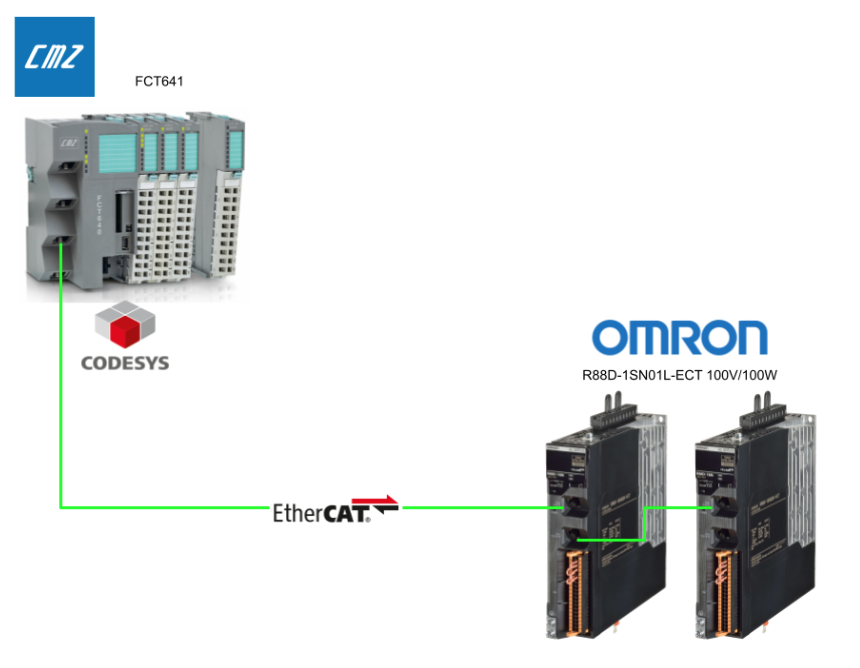
This article shows the use of CODESYS on a CMZ FCT641 motion controller and the connection of two OMRON servo drivers (R88D-1SN01L-ECT) via EtherCAT. motion control, visualisation and online operation are all realised as part of the system.
Come on, let’s enjoy FA.
Foreword
Thank you from the bottom of my heart for visiting my technical blog and YouTube channel.
We are currently running the “Takahashi Chris” radio show with Full-san (full@桜 八重 (@fulhause) / X) which I deliver every Wednesday night.
Sharing, not hoarding, technical knowledge
We publish technical information related to factory production technology and control systems for free, through blogs and videos.
With the belief that “knowledge should be accessible to everyone,” we share practical know-how and real-world troubleshooting cases from our own field experience.
The reason we keep it all free is simple: to help reduce the number of people who struggle because they simply didn’t know.
If you’ve ever thought:
- “Will this PLC and device combination actually work?”
- “I’m having trouble with EtherCAT communication—can someone test it?”
- “I want to try this remote I/O, but we don’t have the testing environment in-house…”
Feel free to reach out!If lending equipment or sharing your configuration is possible, we’re happy to verify it and share the results through articles and videos.
(We can keep company/product names anonymous if requested.)
How can you support us?
Currently, our activities are nearly all unpaid, but creating articles and videos takes time and a proper testing environment.If you’d like to support us in continuing and expanding this content, your kind help would mean a lot.
Membership (Support our radio show)
This support plan is designed to enhance radio with Mr Full.
https://note.com/fulhause/membership/join
Amazon Gift List (equipment & books for content production)
Lists equipment and books required for content creation.
https://www.amazon.co.jp/hz/wishlist/ls/H7W3RRD7C5QG?ref_=wl_share
Patreon (Support articles & video creation)
Your small monthly support will help to improve the environment for writing and verifying articles.
https://www.patreon.com/user?u=84249391
Paypal
A little help goes a long way.
https://paypal.me/soup01threes?country.x=JP&locale.x=ja_JP
Just trying to share things that could’ve helped someone—if only they’d known.
Your support helps make knowledge sharing more open and sustainable.
Thank you for being with us.
soup01threes*gmail.com
Technical knowledge shouldn’t be kept to ourselves.
Reference Link
Equipment and environment used
This is the equipment and environment used in this article.
- CMZ FCT641 Motion Controller (CODESYS SoftMotion compatible)
- EtherCAT servo (OMRON R88D-1SN01L-ECT)
Role of the SoftMotion CiA402 Axis
CiA402 (CANopen Device Profile for Drives and Motion Control) is a common profile standard for servo drives and motion devices, The control of EtherCAT slave drives compliant with this profile is possible by adding “Virtual Axis Objects” with SoftMotion functionality.
Main functions
The following functions can be implemented in the SoftMotion CiA402
- Position control
- Velocity control
- Torque control
- Homing
- State control (Enable, Fault reset, etc.)
When to use it?
The SoftMotion CiA402 Axis is used in the following cases
- SERVO with CiA402-compliant EtherCAT drive, e.g. OMRON R88D, Yaskawa, Beckhoff
- For SoftMotion control on the PLC side
- For flexible control logic with standard Motion FB
Implementation
EDS FILE installation
New devices and fieldbus slaves that were not yet supported on CODESYS can be used. In particular, I/O mappings and configuration parameters are automatically generated by correctly loading the configuration using vendor-supplied EDS files.
From the CODESYS top menu, select ‘Tools’, then ‘Device Repository…’ Select [Tools] in the CODESYS top menu.

Here you can see a list of devices currently registered in CODESYS, categorised as fieldbus, PLC, SoftMotion drives, etc. On the right of the screen there is an ‘Install’ button, from which new device files can be added.

Pressing ‘Install’ displays a dialogue box for selecting a device definition file.

The Windows file selection screen will open and you can select multiple EDS files.

Once the file installation is complete, the OMRON Corporation device will be added to the list and the version and identification name will be visible.

Device configuration and EtherCAT set-up
First set up EtherCAT.
Addition of EtherCAT master
To add an EtherCAT master, first right-click on an existing device and select ‘Add Device…’ from the menu. This will open a window for adding a master device registered in CODESYS.

In the ‘Add Device’ dialog, select the EtherCAT Master SoftMotion from Fieldbuses > EtherCAT > Master and click ‘Add Device’. This master supports the SoftMotion function and enables the control of various servo axes.

You can see that EtherCAT_Master (EtherCAT Master SoftMotion) has been added under Device. After this, you can scan the slave devices for automatic configuration or add devices manually.

NIC settings for EtherCAT communication
Select the EtherCAT Master and go to the ‘General’ setting in the Properties tab.
Instead of entering the MAC address directly, you can select from the list of available network adapters by pressing the “Select…” button on the right. Available network adapters.

From the ‘Select Network Adapter’ window that appears, select the physical port you want to use (e.g. ETH_1); check the MAC address and interface name (e.g. ETH_0 / ETH_1) to ensure they are correct.

After selection, the “Source address (MAC)” field of the EtherCAT Master automatically reflects the address of the selected interface. In this state, the EtherCAT communication can be initialised.

Slave device registration (OMRON Servo)
Right-click on EtherCAT_Master and select ‘Add Device…’ Select ‘Add Device…’. This is a preparatory step for manually adding a slave device. Use this step if the device is not detected by the automatic scan or if you want to build up a specific configuration manually.

Vendor selection
In the ‘Add Device’ screen, setting ‘Vendor’ to OMRON Corporation narrows down the list of EtherCAT slave devices (e.g. drives and I/Os) manufactured by OMRON.

OMRON R88D servo drive selection
Select the R88D-1SN01L-ECT 100V/100W ServoDrive under OMRON Corporation > Servo Drives. The device must have an EDS (EtherCAT Slave Description) file imported into CODESYS beforehand.

Servo drive configuration complete.
Two R88D servo drives have been added under EtherCAT_Master. The physical drives now match the configuration on CODESYS.

Right-click on each drive and select ‘Add SoftMotion CiA402 Axis’ to add the corresponding SoftMotion axis (Generic DSP402). This operation ensures that the drive is recognised as a motion control target.

Completed configuration tree
In the configuration tree, you can see SM_Drive_GenericDSP402_Axis1 / Axis2 connected to the two R88D drives respectively. In this state, you are ready to proceed with axis parameterisation and motion programming.

SoftMotion axis configuration and programme design
Check that a SoftMotion axis (e.g. SM_Drive_GenericDSP402_Axis1) has been correctly added to each drive under EtherCAT. This is the starting point and is connected to the subsequent control programme.

Scaling and mapping settings
The ‘Scaling/Mapping’ setting for each axis sets the incremental resolution of the motor (e.g. 10#8388608). This is adjusted according to the number of encoder pulses and gear ratio.

Axis control function block (fbAxis)
Create a FB (Function Block) called fbAxis under Application. This is a template FB for axis control to process various MC (Motion Control) blocks together.

ST (Structured Text) declaration section of fbAxis
Declare an axis reference of type AXIS_REF_SM3 in VAR_IN_OUT (now linked to the real axis) and define Motion Control standard FBs (MC_Power, MC_Jog, MC_Home, etc.) in the VAR. This allows standard motion control functions to be used immediately by simply instantiating the fbAxis.
| FUNCTION_BLOCK fbAxis VAR_IN_OUT AXIS_REF_SM3: AXIS_REF_SM3; END_VAR VAR_OUTPUT END_VAR VAR _mc_power:SM3_Basic.MC_Power; _mc_jog: SM3_Basic.MC_Jog; _mc_Reset:SM3_Basic.MC_Reset; _mc_halt:SM3_Basic.MC_Halt; _mc_Stop:SM3_Basic.MC_Stop; _mc_readStatus:SM3_Basic.MC_ReadStatus; _mc_moveRel: SM3_Basic.MC_MoveRelative; _MC_HOME: SM3_Basic.MC_Home; _mc_Readpos: SM3_Basic.MC_ReadActualPosition; _mc_readVel: SM3_Basic.MC_ReadActualVelocity; _mc_readAxisError: SM3_Basic.MC_ReadAxisError; END_VAR |
Axis control FB internal
Standard motion FBs such as MC_Power / MC_MoveVelocity / MC_Jog / MC_Home are located within fbAxis. These are PLCopen-compliant Motion Control instructions and are linked to the respective axis with AXIS_REF_SM3.

Axis instance control by programme (pAxis)
pAxis (PRG) is the programme (POU) to invoke an instance of each axis. Here fbAxis is instantiated for each axis and the parameters and axis number are passed. It also manages instances for multi-axis control and registers them with the task scheduler for periodic control.

Creation of axis instances
| PROGRAM pAxis VAR _Axis1: fbAxis; _Axis2: fbAxis; END_VAR |
This is how fbAxis is connected to SM_Drive_GenericDSP402_Axis1 and Axis2 within pAxis. The logical connection of each axis object to the control block enables control at runtime.

task configuration to pAxis
In Task Configuration, bind the pAxis program that controls the EtherCAT axes to the EtherCAT_Task. This enables the axis control to be executed in a cyclic task.

EtherCAT_Task configuration screen. Registering pAxis in a task that is executed in cycles (e.g. 4 ms) enables near real-time motion control. Priority and monitoring settings can also be adjusted here.

Visualisation screen construction
Introduction of template structures.
The next step is to set up a common visualisation screen called ‘Template’. The main advantages are:
- Batch management of motion control panels (Power, Jog, Move, etc.) common to each axis
- Improved design efficiency by copying and reusing components
- Improved visibility through design unification
The following main blocks are located within the Template screen:
| block name | functional overview |
| MC_Power | Servo power ON/OFF control |
| MC_Reset | error cancellation |
| MC_Jog | error cancellation |
| MC_MoveRelative | relative motion instruction |
| MC_ReadStatus | Status monitoring of axes (e.g. during stop, homing, etc.) |
| MC_ReadAxisError | Check error codes |
| MC_ReadActualPosition | Obtaining the current position |

Visualisation Toolbox ‘SM3_Basic’ tab.
Here you will find visualisation part templates specifically for SoftMotion. They are divided by application and can be easily added to the screen by drag and drop.
- MC_Power: power on/off of the axis
- MC_Reset: error reset
- MC_Jog: manual JOG operation (forward/backward)
- MC_MoveRelative: relative position move
- MC_ReadStatus: status monitoring
- MC_ReadActualPosition / Velocity / AxisError: visualisation of current values

Template utilisation structure
The next step is to add the upper layout (Template) and the lower footer (Template_Footer) to the axis-specific operation screen (e.g. Axis-1) by drag & drop.

Next, on the Visualisation screen, right-click on Template → Properties>References section, for fbRefAxis, click on the … button in the Properties>References section.
Select _Axis1 (type: fbAxis) under the programme pAxis.

We have confirmed that pAxis._Axis1 is correctly set in bRefAxis.

Setting up and publishing WebVisu
In Visualisation Manager > WebVisu, the Start visualisation item should also set the first visual screen to be displayed in the web browser (e.g. Axis 1).

Axis1 / Axis2 Visualisation screen
A position graph is also provided at the bottom of the screen, allowing the user to visually check the transition of the axis position over time. The configuration also allows the user to switch between axis screens using the AXIS1 and AXIS2 switching buttons.

communication settings
Double-click on the device>Select ‘Communication Settings’ from the left menu.

Click on the ‘Scan Network’ button> Connectable FCT641 devices are detected.

Select FCT641 from the options and activate it with ‘Enter’.

Log in to device
From the menu: Online > Login, the device and CODESYS IDE are connected and the application is downloaded.

start The execution
Click the Play button (F5) to start the PLC application.

Result
The application is now connected to the CMZ FCT641 motion controller on CODESYS and the application is running successfully (Application [run]). In addition, two OMRON R88D-1SN01L-ECT servo drives are connected under the distribution and communicating normally.

The operation of the actual machine can be checked in the demonstration video uploaded on YouTube.