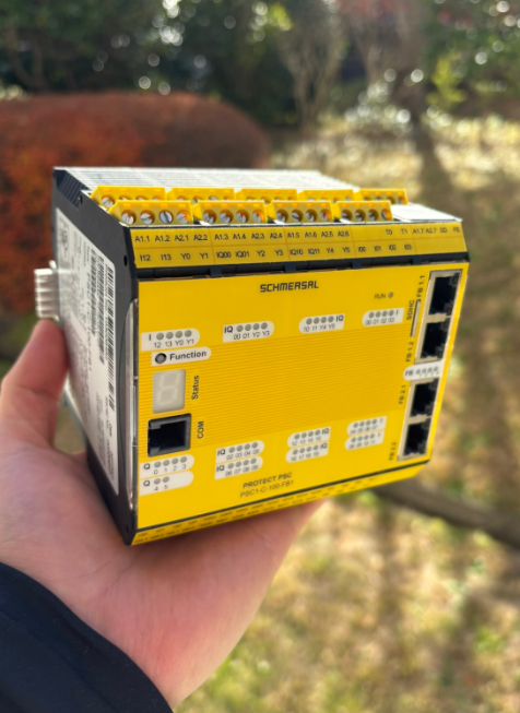
This is a new series, in which various articles will be developed using the PSC1-C-100-FB1 Safety Controller from Schmersal. Episode 4 is connected to the Pilz light curtain and explains how to use Groups.
Come on, let’s enjoy FA.
Foreword
Thank you from the bottom of my heart for visiting my technical blog and YouTube channel.
We are currently running the “Takahashi Chris” radio show with Full-san (full@桜 八重 (@fulhause) / X) which I deliver every Wednesday night.
Sharing, not hoarding, technical knowledge
We publish technical information related to factory production technology and control systems for free, through blogs and videos.
With the belief that “knowledge should be accessible to everyone,” we share practical know-how and real-world troubleshooting cases from our own field experience.
The reason we keep it all free is simple: to help reduce the number of people who struggle because they simply didn’t know.
If you’ve ever thought:
- “Will this PLC and device combination actually work?”
- “I’m having trouble with EtherCAT communication—can someone test it?”
- “I want to try this remote I/O, but we don’t have the testing environment in-house…”
Feel free to reach out!If lending equipment or sharing your configuration is possible, we’re happy to verify it and share the results through articles and videos.
(We can keep company/product names anonymous if requested.)
How can you support us?
Currently, our activities are nearly all unpaid, but creating articles and videos takes time and a proper testing environment.If you’d like to support us in continuing and expanding this content, your kind help would mean a lot.
Membership (Support our radio show)
This support plan is designed to enhance radio with Mr Full.
https://note.com/fulhause/membership/join
Amazon Gift List (equipment & books for content production)
Lists equipment and books required for content creation.
https://www.amazon.co.jp/hz/wishlist/ls/H7W3RRD7C5QG?ref_=wl_share
Patreon (Support articles & video creation)
Your small monthly support will help to improve the environment for writing and verifying articles.
https://www.patreon.com/user?u=84249391
Paypal
A little help goes a long way.
https://paypal.me/soup01threes?country.x=JP&locale.x=ja_JP
Just trying to share things that could’ve helped someone—if only they’d known.
Your support helps make knowledge sharing more open and sustainable.
Thank you for being with us.
soup01threes*gmail.com
Technical knowledge shouldn’t be kept to ourselves.
Reference Video
Schmersal.Open box with PSC1-C-100-FB1!
Reference Link
http://soup01.com/en/category/schmersal_en/psc1-en/
Light Curtain
This is a connection type where the Light Curtain component can be set up on SafeyPLC2.
| Switch type | Connections | Description |
| 1 (2 N.C.) | N.C.x2 | light curtain |
| 2 (2 N.C. Time Monitored) | N.C.x2 + time monitoring | Light curtains with time monitoring function |
| 3 (1 N.O. 1 N.C.) | N.C. x1、N.O. x 1 | light curtain |
| 4 (1 N.O. 1 N.C. Time Monitored) | N.C. x 1, N.O. x 1 + time monitoring | Light curtains with time monitoring function |
Groups
Function groups combine several function modules into an encapsulated logic structure. This grouping gives the function block diagram a clearer structure and the export/import function allows you to create your own function libraries.
Implementation
This is the structure of this article.
Schmersal Side
This article is a continuation of Part 2.
Add Light Curtain
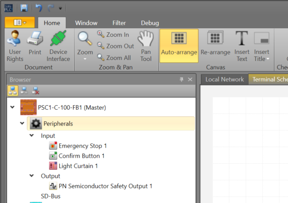
Add the Input>Light Curtain component from the Library.
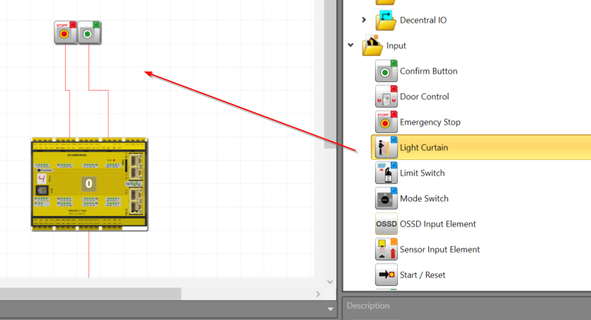
Done!
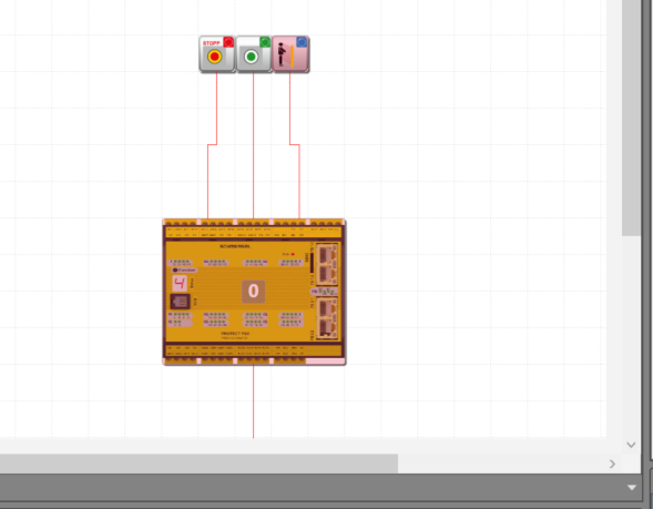
A Light Curtain component has also been added to the Peripherals Menu.
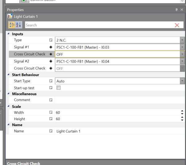
Configure Light Curtain Object
Click on the Light Curtain component > Properties to change the connection settings.

This is the setting for this article.
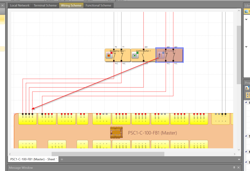
The Wiring Scheme Tab also displays the wiring diagram for the Light Curtain that has been added this time.
Safety Program
We will now create a safety programme: open Functional Sheets and add the Light Curtain component to the Functional Sheets.
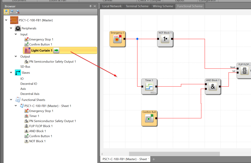
Done!
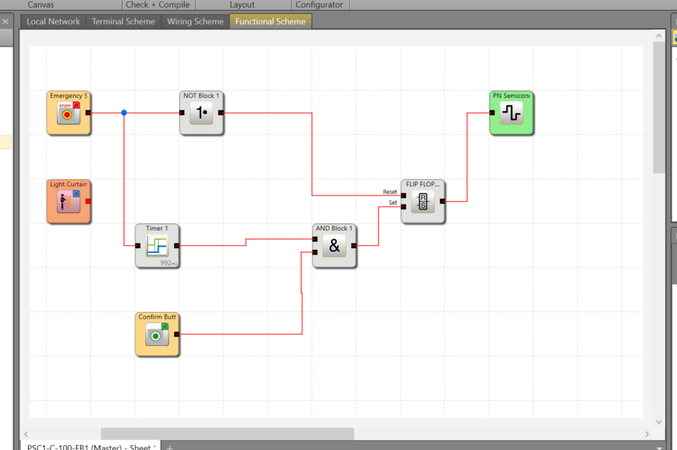
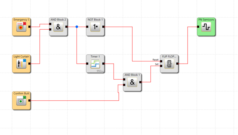
Add an AND Block and connect it to the Light Curtain component and the emergency stop input.
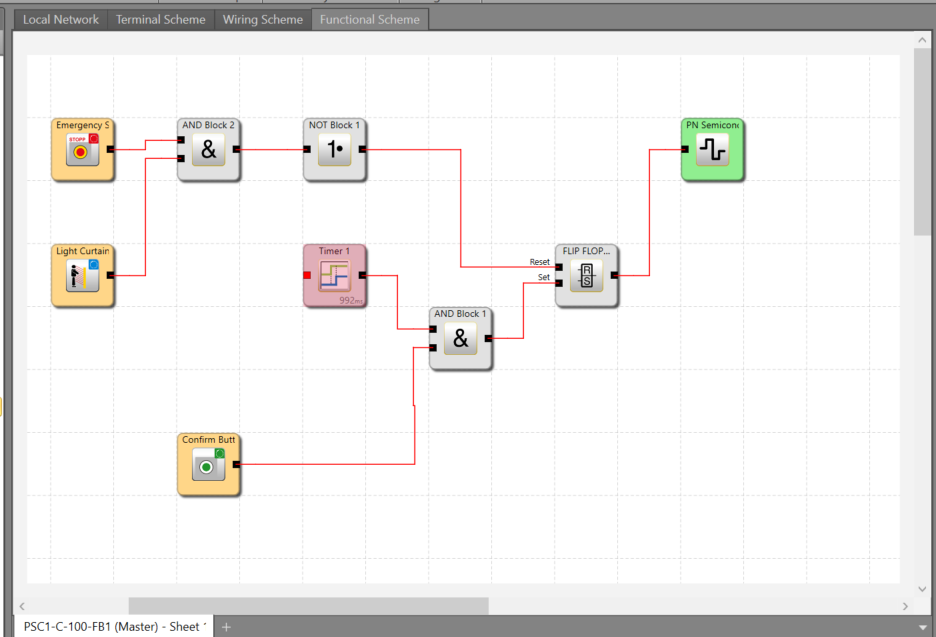
Finally, connect the input of the timer to the output of the AND Block.
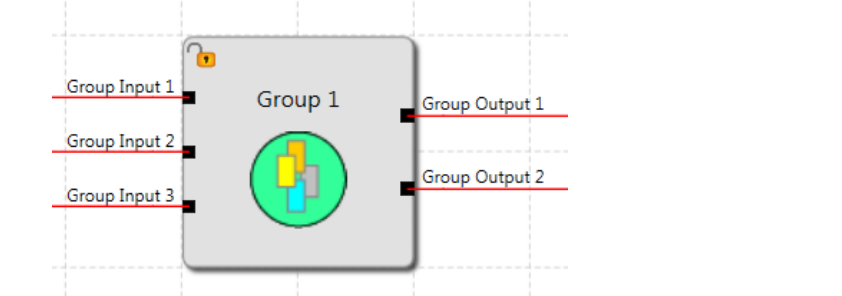
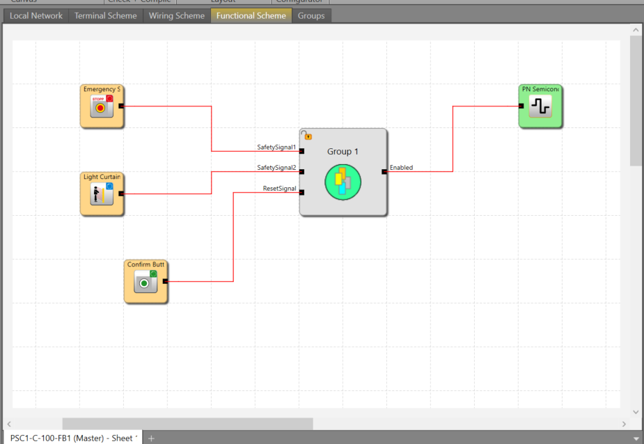
Create Groups
The logic in the red box section is now also set and reset programmed, so the Groups function is used to encapsulate the partial programme.
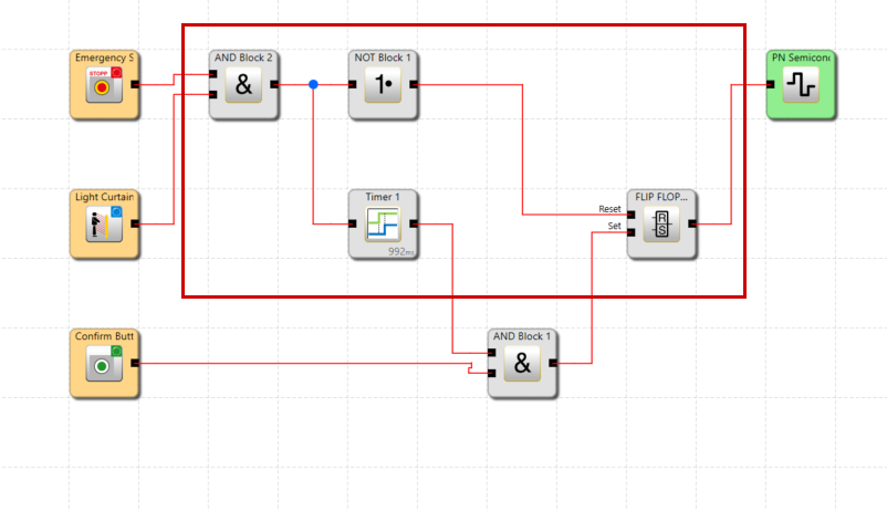
Select all the parts you want to Group > right-click > click Create a new group from selection.
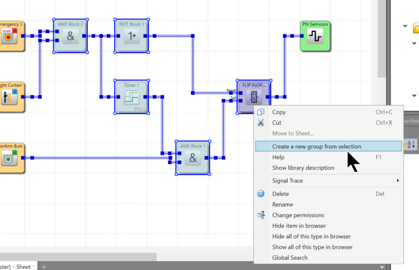
Done!The set/reset logic added earlier is now Group.
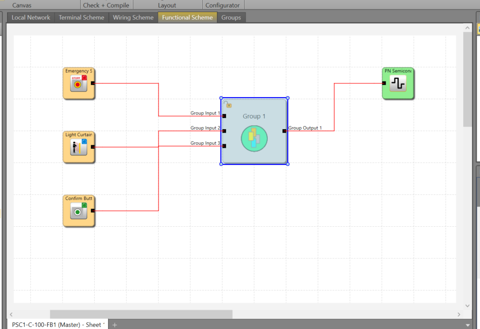
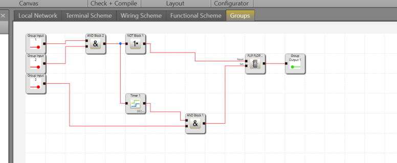
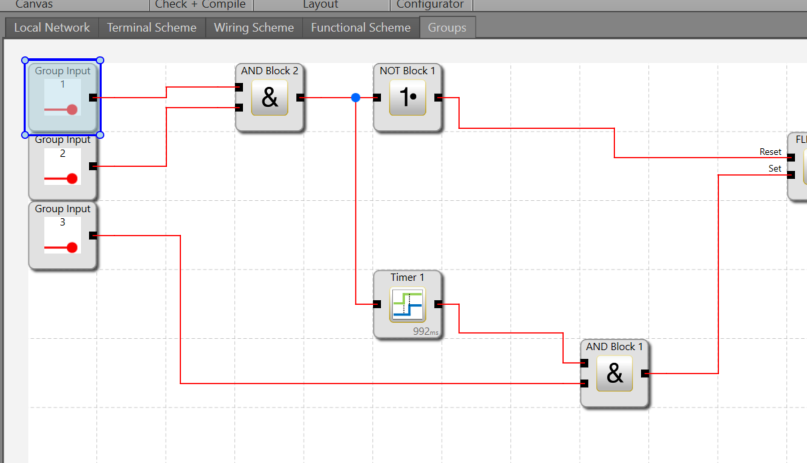
The inside of the Group is exactly the same.
Group inputs and outputs are difficult to understand with Default names, so they will be changed.
Change the name in the Name Field to a name that is easy to understand.
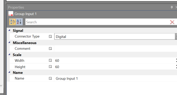
Done!
Connect to the Controller
Connect the COM Port of the PSC1-C-100-FB1 and the dedicated cable to the PC.
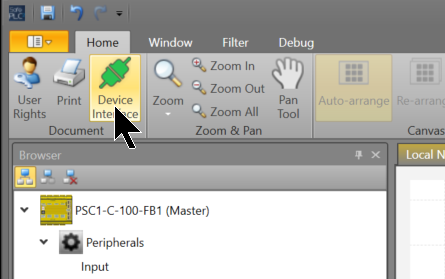
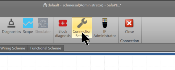
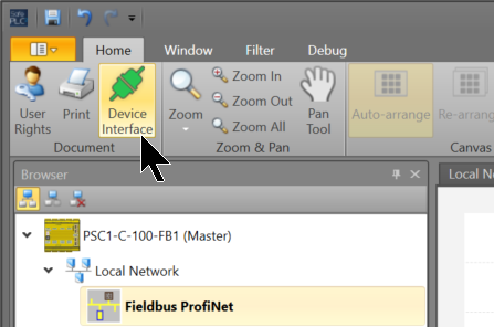
Click SafePLC2>Home>Device Interface.
Connection Settingsをクリックします。
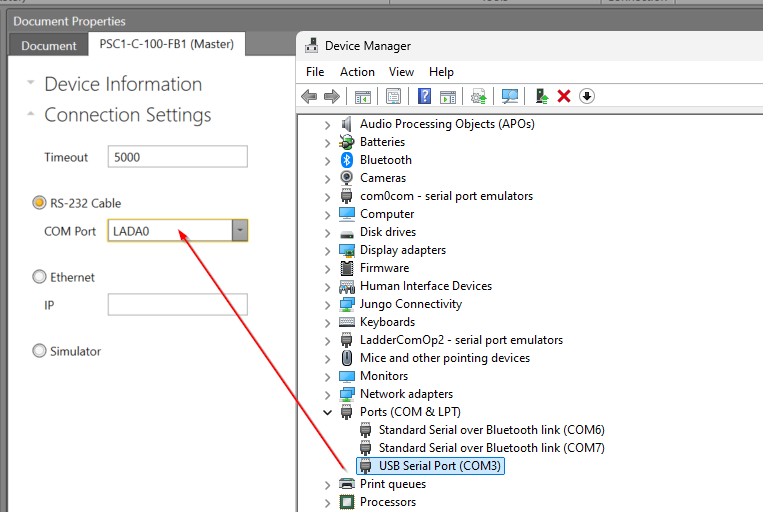
As you will be using an RS-232 cable, you should set the COM Port to match the Device Manager.
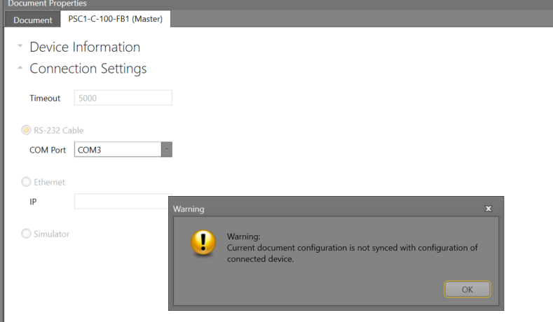
Finally, click on the Connect button to connect the CPU and SafePLC2.
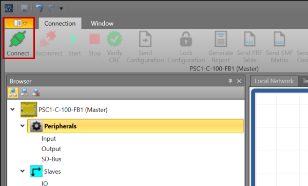
OK to proceed. So I connected the SafePLC2 to the PSC1-C-100-FB1.
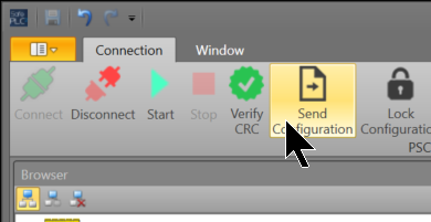
Send Configuration
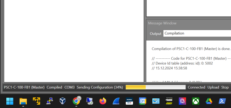
Click Send Configuration to transfer your project to PSC1-C-100-FB1.
Please wait a moment…
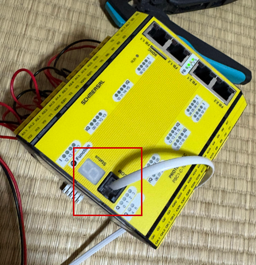
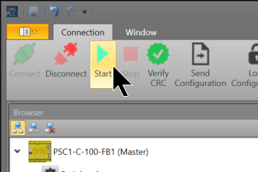
Start
Finally, click the Start button to set the PSC1-C-100-FB1 CPU to RUN MODE.
Monitor
The SafePLC tool also has IO and programme monitoring functions – click on Device Interface.
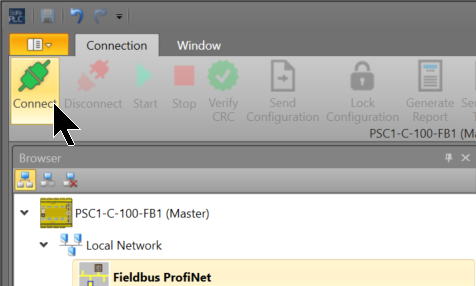
Click Connect to connect the PC to the PSC1-C-100-FB1.
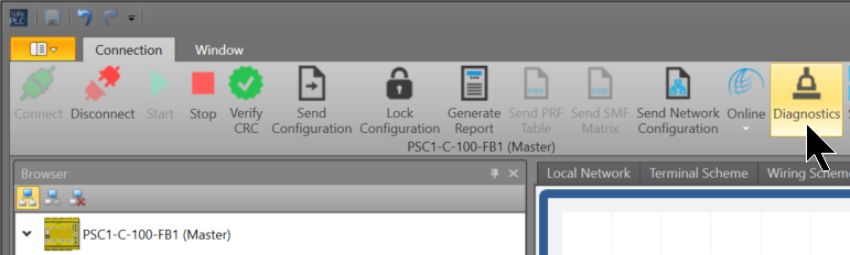
Next, click on Diagnostics.
Result
Check the operation from this video.