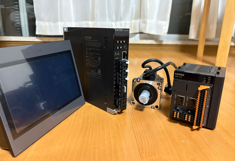
This is a new series where we’ll be using FATEK’s M-PLC to explore various topics. In Episode 2, we’ll connect to FATEK’s SC3 servo motor—the same as the M-PLC—and operate the Test Run.
Let’s enjoy FA.
Foreword
Thank you from the bottom of my heart for visiting my technical blog and YouTube channel.
We are currently running the “Takahashi Chris” radio show with Full-san (full@桜 八重 (@fulhause) / X) which I deliver every Wednesday night.
Sharing, not hoarding, technical knowledge
We publish technical information related to factory production technology and control systems for free, through blogs and videos.
With the belief that “knowledge should be accessible to everyone,” we share practical know-how and real-world troubleshooting cases from our own field experience.
The reason we keep it all free is simple: to help reduce the number of people who struggle because they simply didn’t know.
If you’ve ever thought:
- “Will this PLC and device combination actually work?”
- “I’m having trouble with EtherCAT communication—can someone test it?”
- “I want to try this remote I/O, but we don’t have the testing environment in-house…”
Feel free to reach out!If lending equipment or sharing your configuration is possible, we’re happy to verify it and share the results through articles and videos.
(We can keep company/product names anonymous if requested.)
How can you support us?
Currently, our activities are nearly all unpaid, but creating articles and videos takes time and a proper testing environment.If you’d like to support us in continuing and expanding this content, your kind help would mean a lot.
Membership (Support our radio show)
This support plan is designed to enhance radio with Mr Full.
https://note.com/fulhause/membership/join
Amazon Gift List (equipment & books for content production)
Lists equipment and books required for content creation.
https://www.amazon.co.jp/hz/wishlist/ls/H7W3RRD7C5QG?ref_=wl_share
Patreon (Support articles & video creation)
Your small monthly support will help to improve the environment for writing and verifying articles.
https://www.patreon.com/user?u=84249391
Paypal
A little help goes a long way.
https://paypal.me/soup01threes?country.x=JP&locale.x=ja_JP
Just trying to share things that could’ve helped someone—if only they’d known.
Your support helps make knowledge sharing more open and sustainable.
Thank you for being with us.
soup01threes*gmail.com
Technical knowledge shouldn’t be kept to ourselves.
Reference Link
http://soup01.com/en/category/fatek_en/m-series-en/
http://soup01.com/en/category/fatek_en/sc-series-en/
TestRun?
TestRun is a motion control function designed exclusively for UperLogic and is a built-in function. There are three methods for executing motion control with the M-PLC controller:
- Ladder Control
- Motion Flow
- TestRun
When commissioning, the TestRun function is the quickest, most convenient, and simplest method, as it allows you to perform servo operation tests without writing a single line of PLC ladder program or motion flow control process.
Implementation
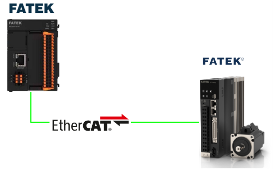
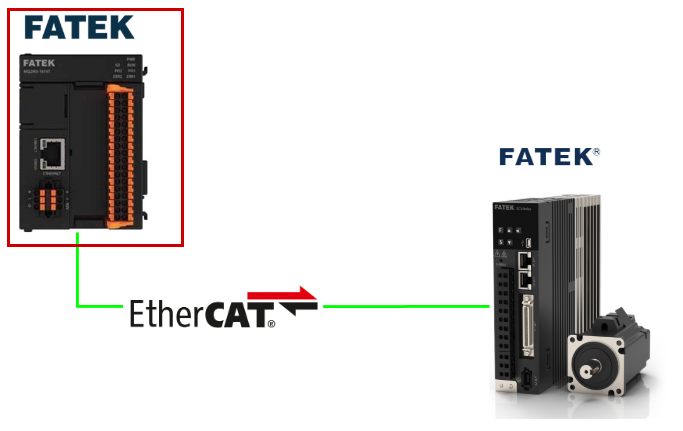
This article’s setup connects FATEK’s M-PLC with the SC3 series servo via EtherCAT. Now let’s perform a TestRun on the M-PLC.
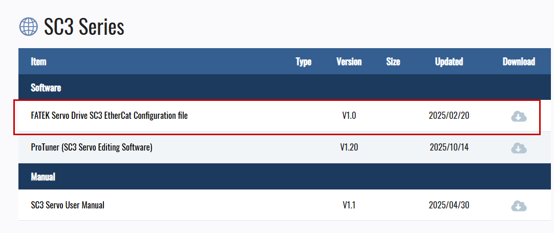
Download the ESI file
Download the ESI file for the FATEK SC3 series servo used in this article from the link below.
https://www.fatek.com/en/download.php?act=list&cid=175
M-PLC Side
We will build the FATEK M-PLC side.
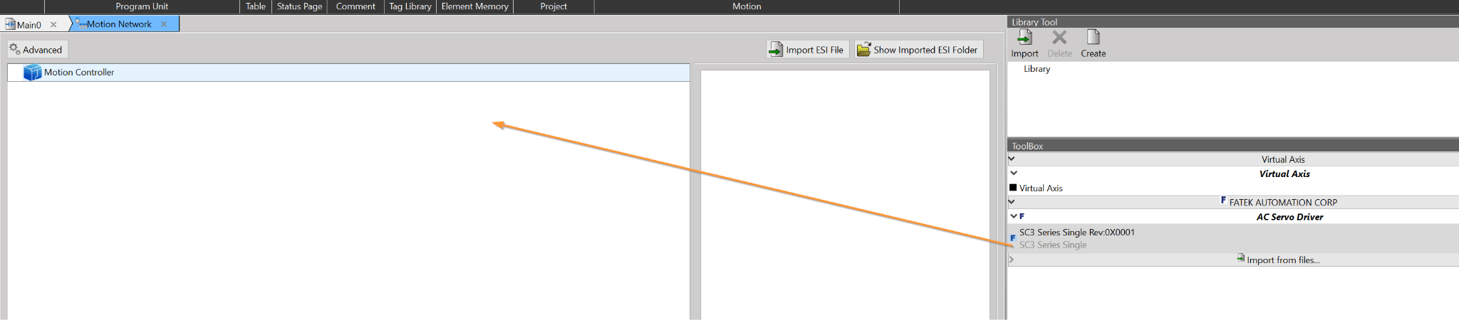
Configure EtherCAT Network
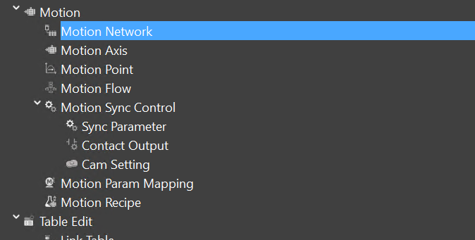
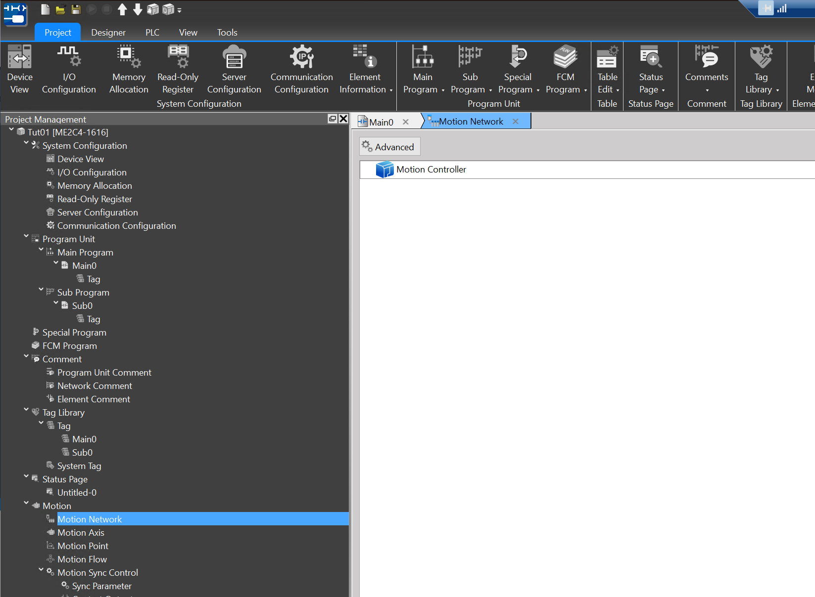
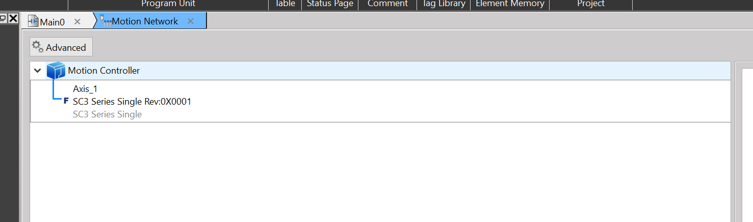
To add an EtherCAT Slave to the project, click Motion → Motion Network.
This is the EtherCAT network configuration screen in UperLogic.
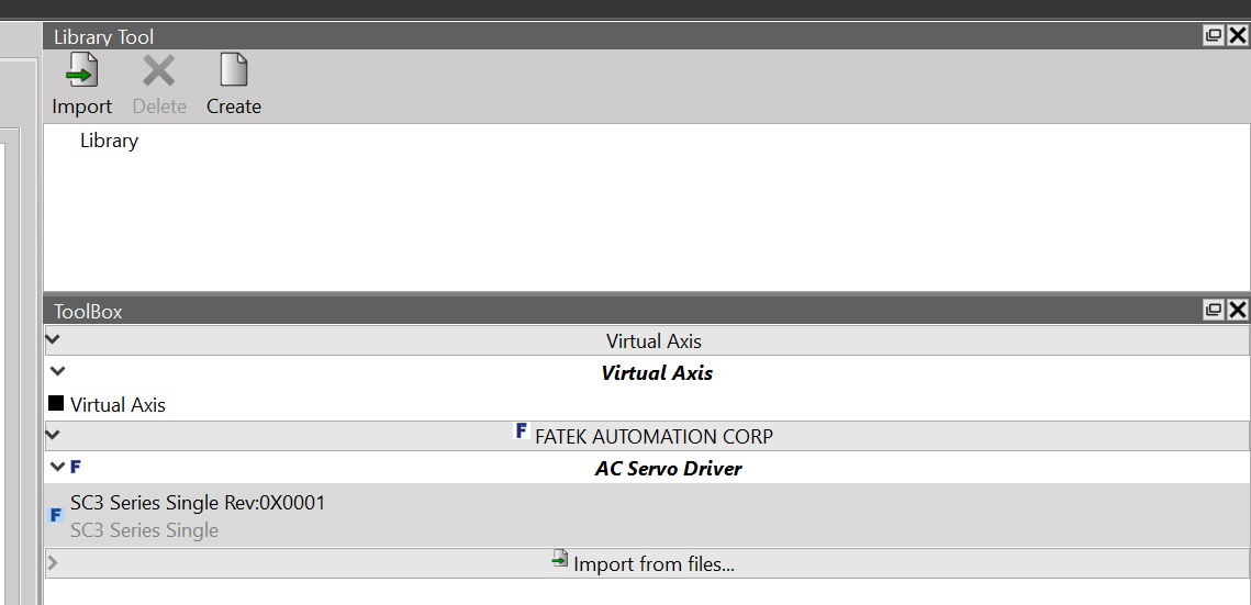
Import ESI file
Import from Library Tool on the right side of UperLogic.
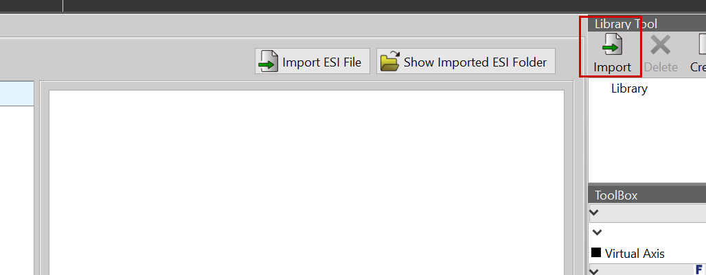
Click on the ESI file that was downloaded earlier.
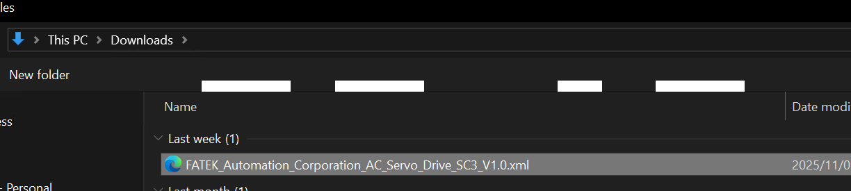
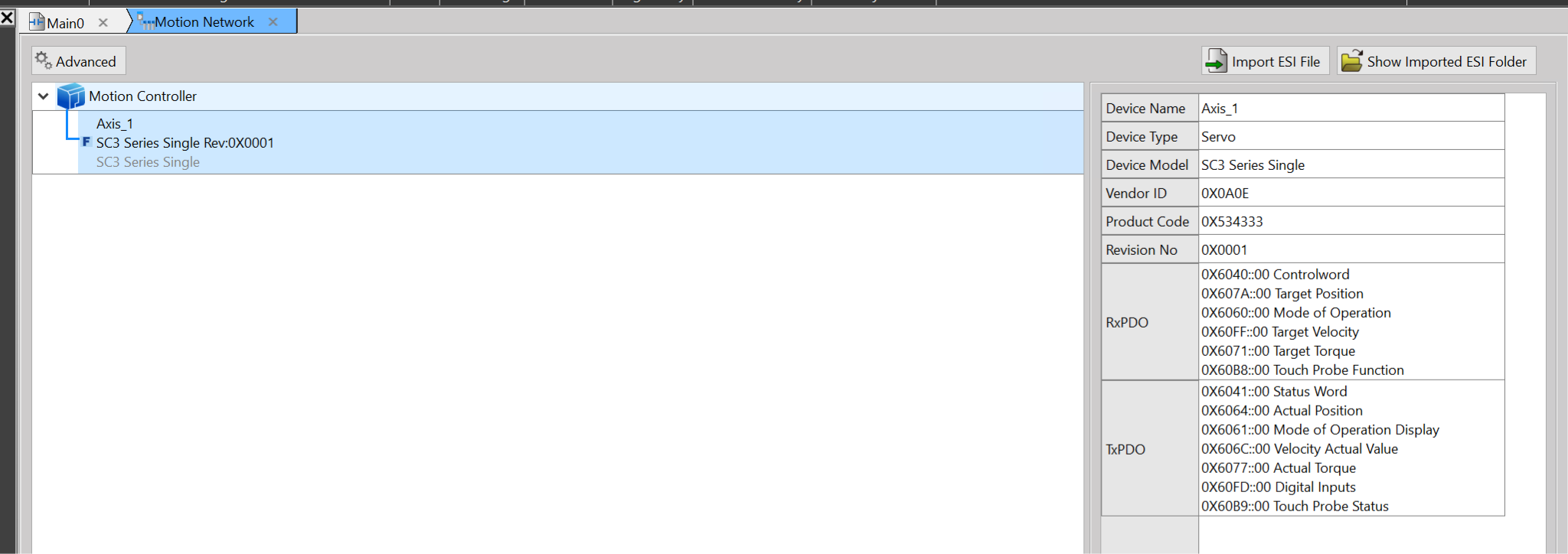
Done! The ESI file has been successfully imported.
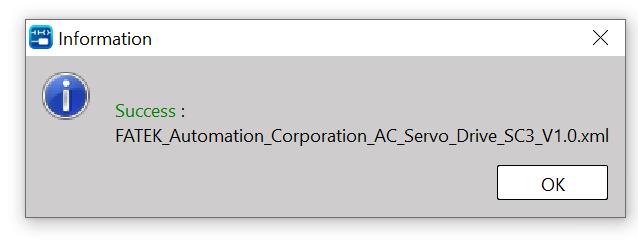
The FATEK SC3 series servo has now been imported.
Add SC3 servo
Add the SC3 servo to the Motion Controller.
Done!
PDO Setting
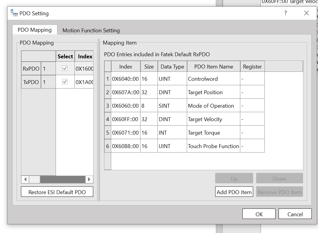
If you want to change the PDO Mapping of an EtherCAT Slave, select the corresponding axis → click PDO Settings.
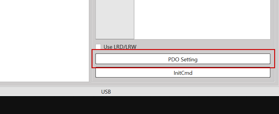
Let’s add PDOs according to your actual application.
Download
Next, let’s download the project to the PLC via PLC→Download.
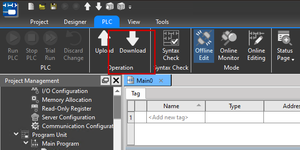
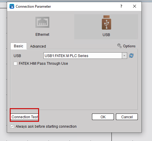
The parameter setting screen for connecting to the PLC will be displayed.
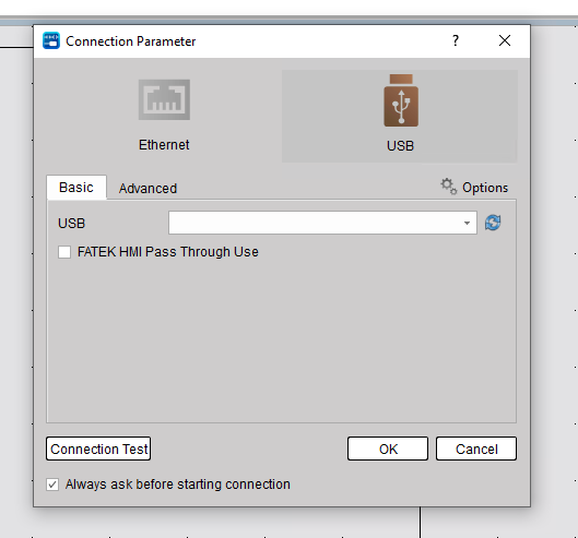
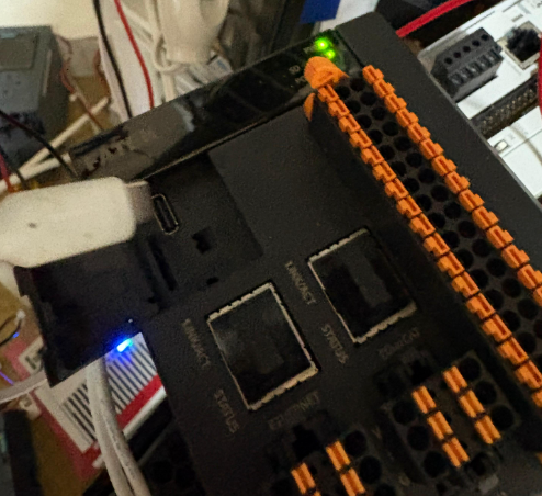
Connect the M-PLC to your PC using the USB-C port on the main unit.
If the USB Driver does not appear, please click the button highlighted in red in the image below.
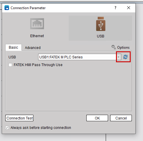
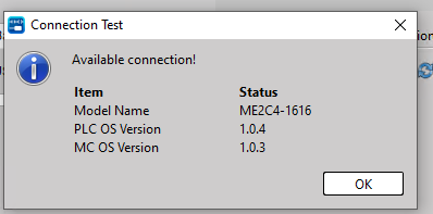
Next, click the Connection Test button in the lower-left corner to perform a communication test.
Done! The connection between the PC and PLC is working properly. Now click OK to download the project to the PLC.
Check the different locations for Offline and Online, then click the Download button.Check the different locations for Offline and Online, then click the Download button.
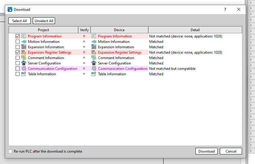
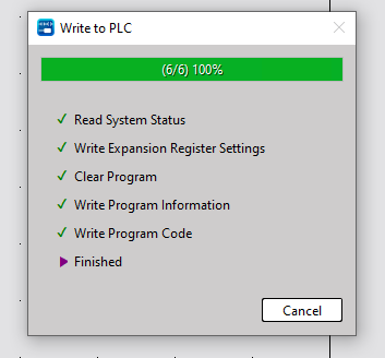
Done!
Motion Axis
Next, to configure the axis settings, go to Motion → Axis.
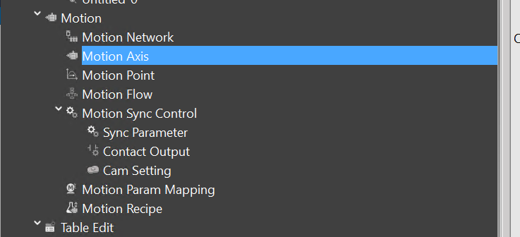
This is the servo settings screen.
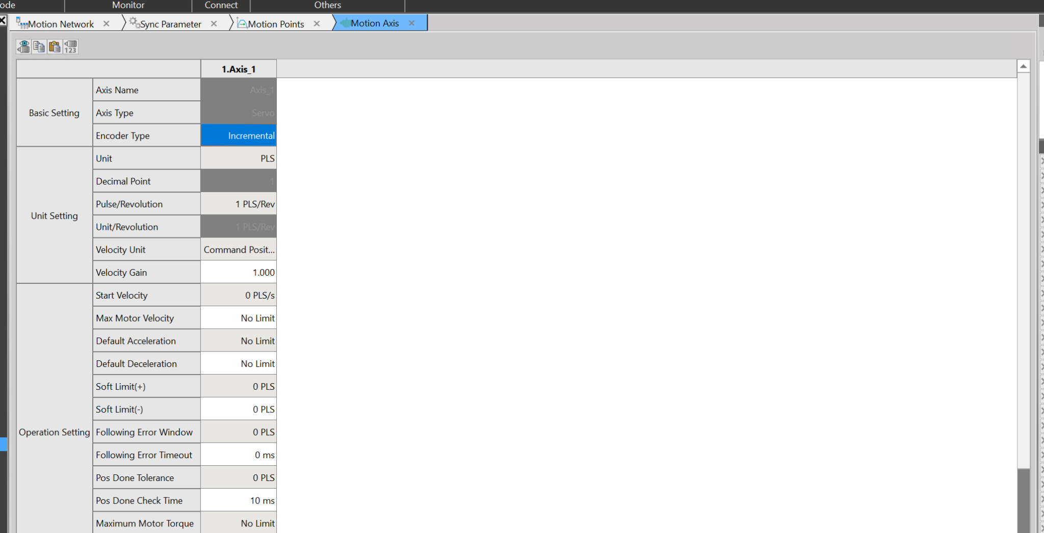
Configure according to the servo type that adopts the encoder type.
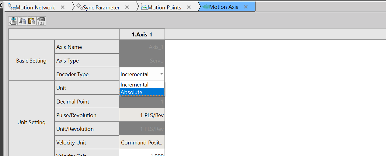
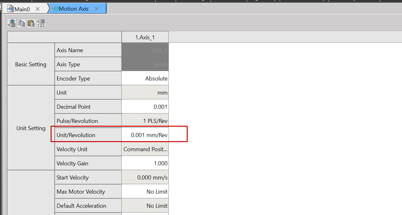
This is where you set the units. This time, we’ll set it to mm.
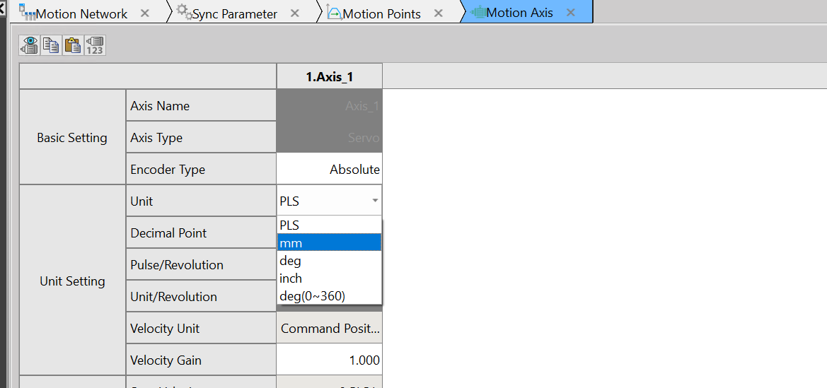
Unit Revolution sets the mm per revolution.
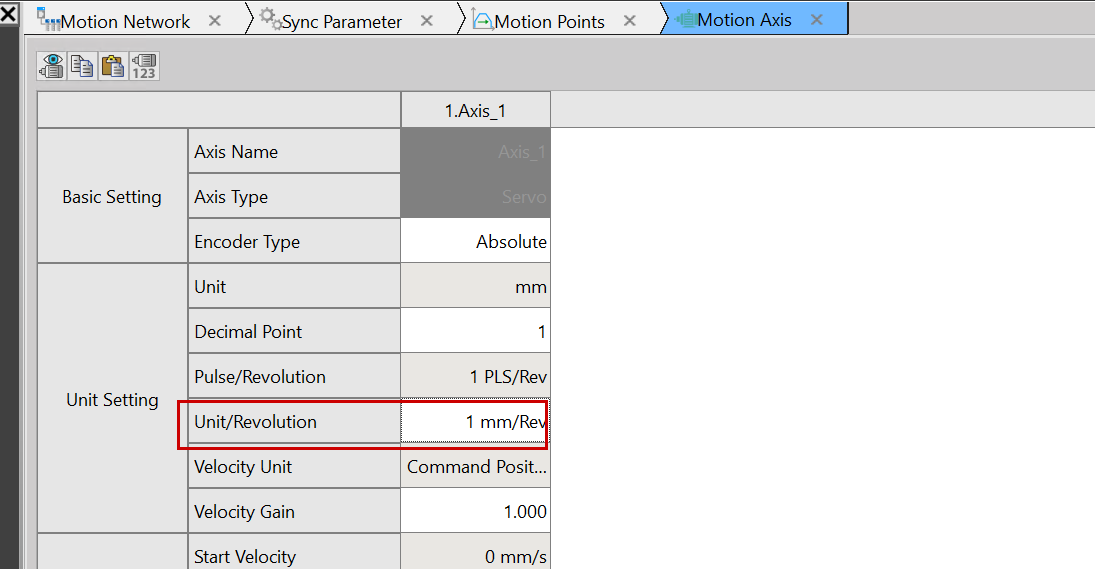
This time, we will set 6mm to equal one rotation.
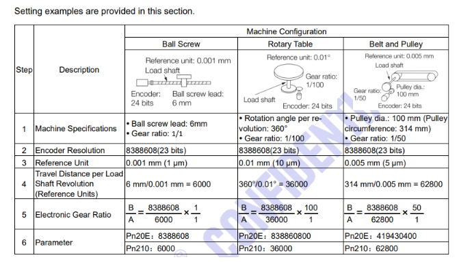
This is an explanation of the SC3 series (it bears a striking resemblance to some Japanese manufacturer’s manual, but let’s put that aside for now). This explains the resolution setting for Fatek’s SC3 servo motor. For this article, we’re using the Ball Screw type with 6mm/0.001m, and the Reference Unit is set to 0.001.
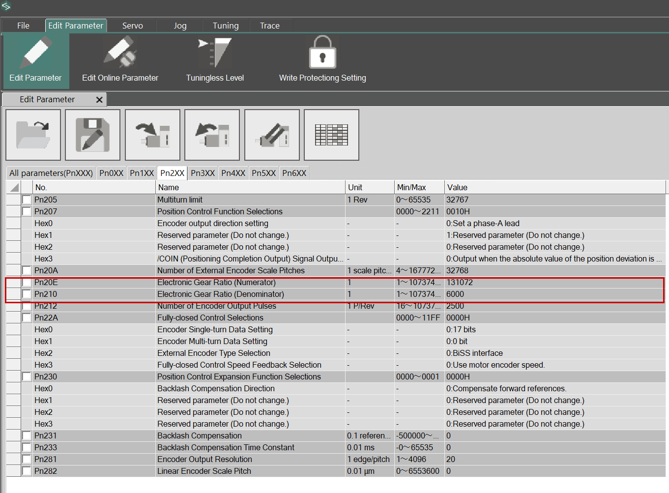
This time, we will set Pn210 with Pn20E=131072. The servo motor used in the article has a resolution of 17 bits, and one revolution is set to 6000 (unit: mm).
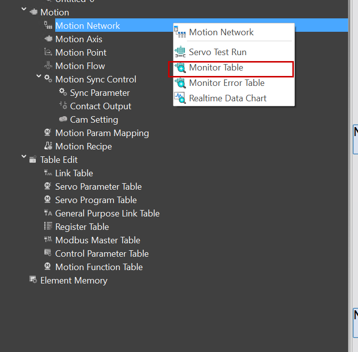
Monitor Table
Motion Table allows you to check the status of each axis. Click Motion → Motion Network → Motion Network.
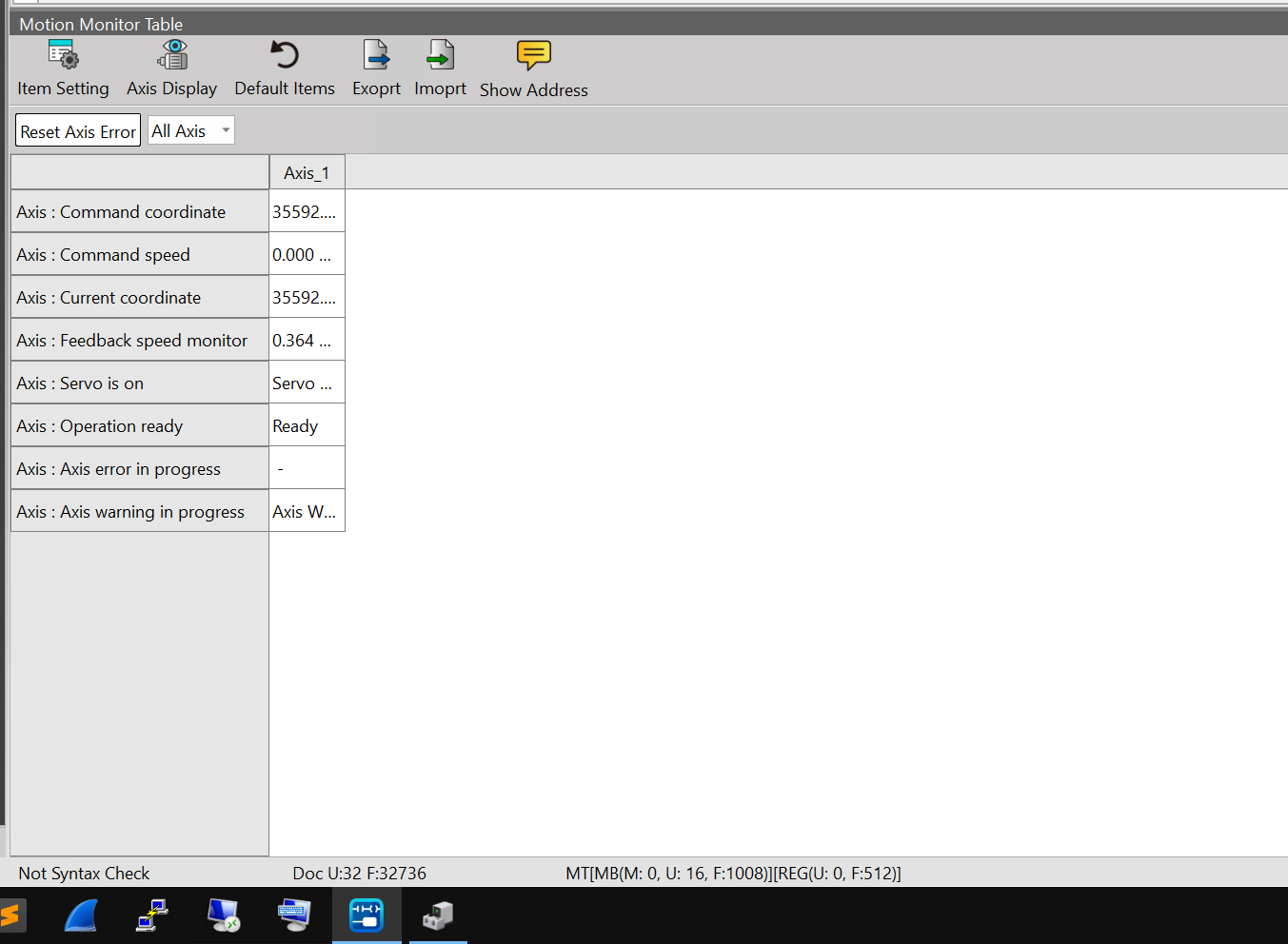
Here you can check the current status of the axes.
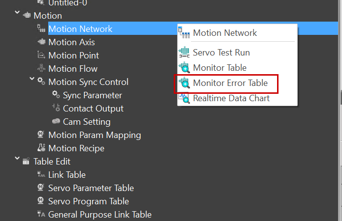
Monitor Error Table
To check the error status of the axes, click Motion → Motion Network → Motion Error Table.
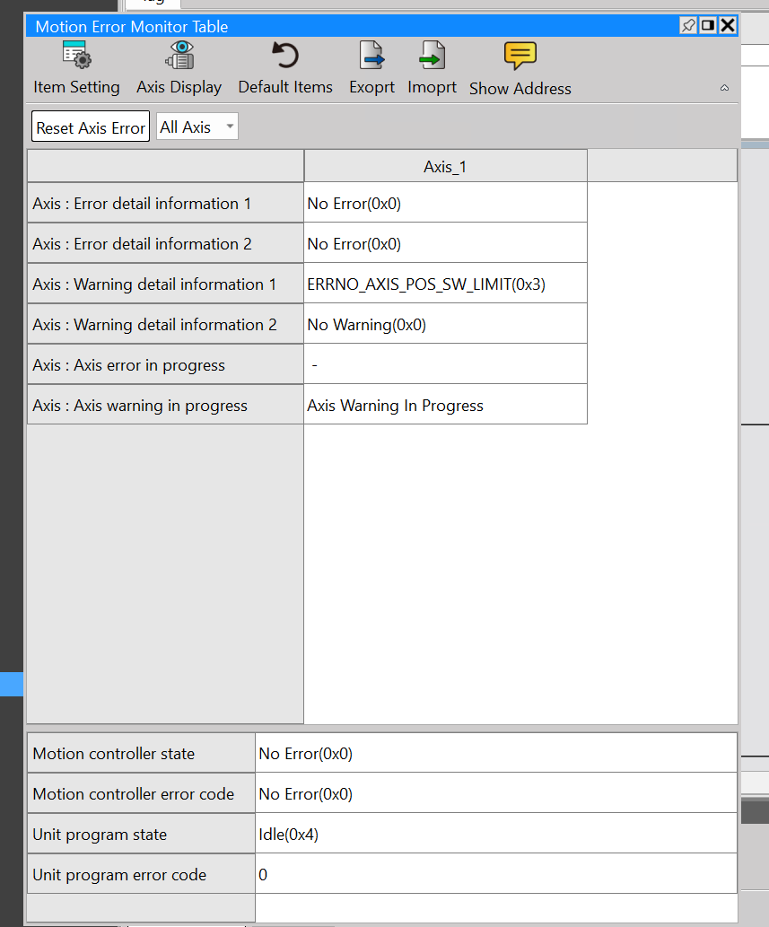
The Motion Error Monitor Table is a diagnostic screen that visualizes the error, warning, and progress status of each axis managed by the MPIC in a list format.
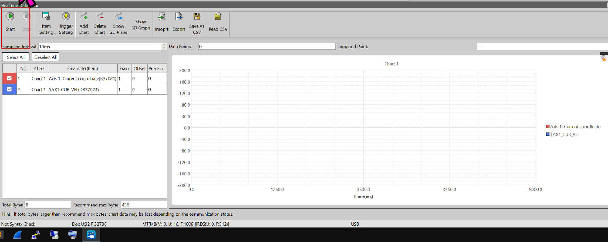
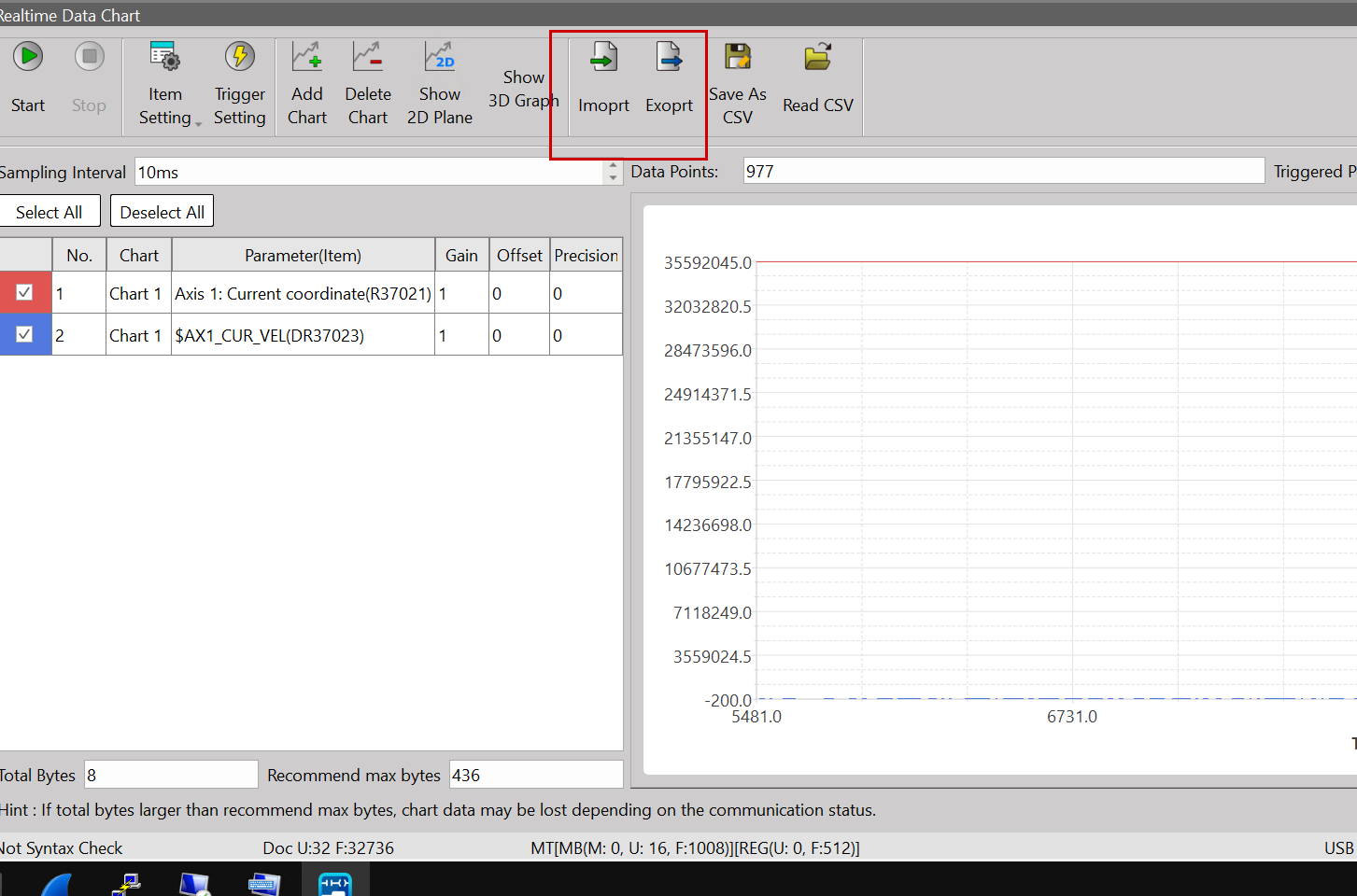
Real Time Chart
Next, click Motion → Motion Network → Realtime Data Chart.
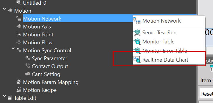
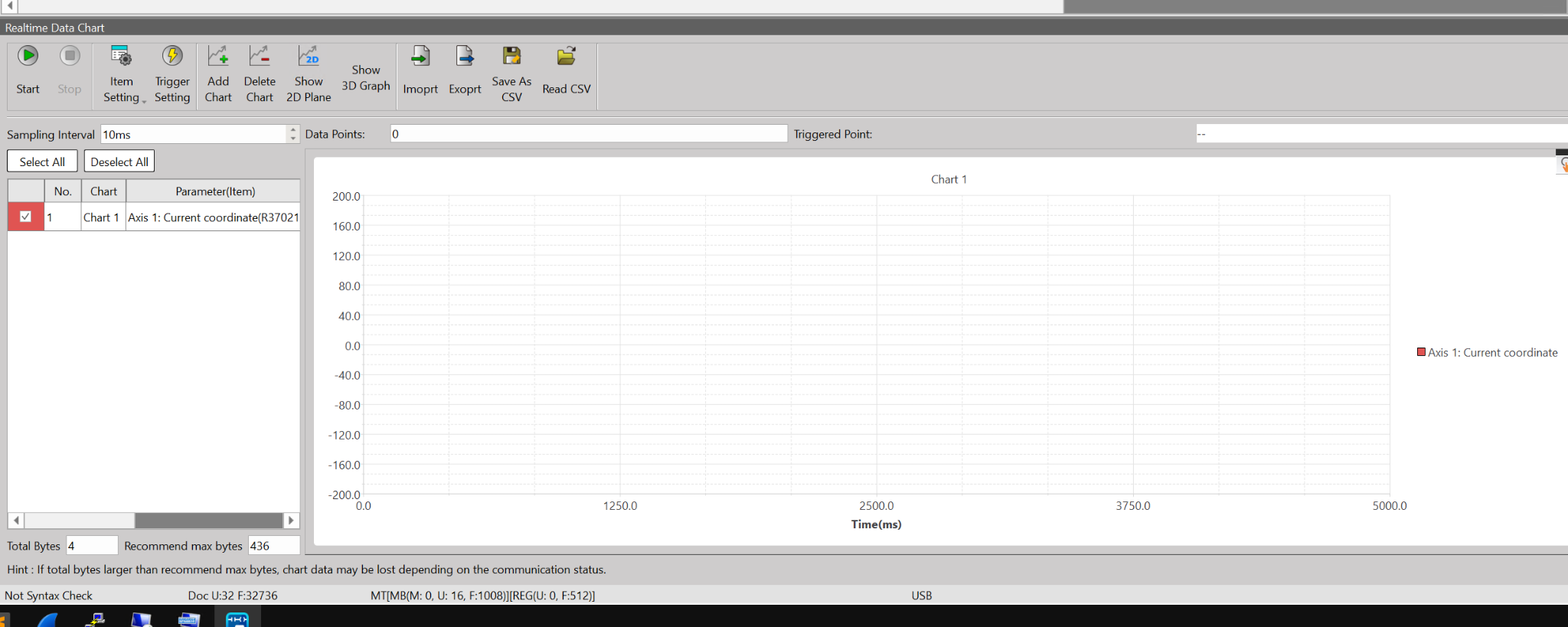
The Realtime Data Chart is a tool for real-time visualization of internal motion axis data over time.
Add Chart
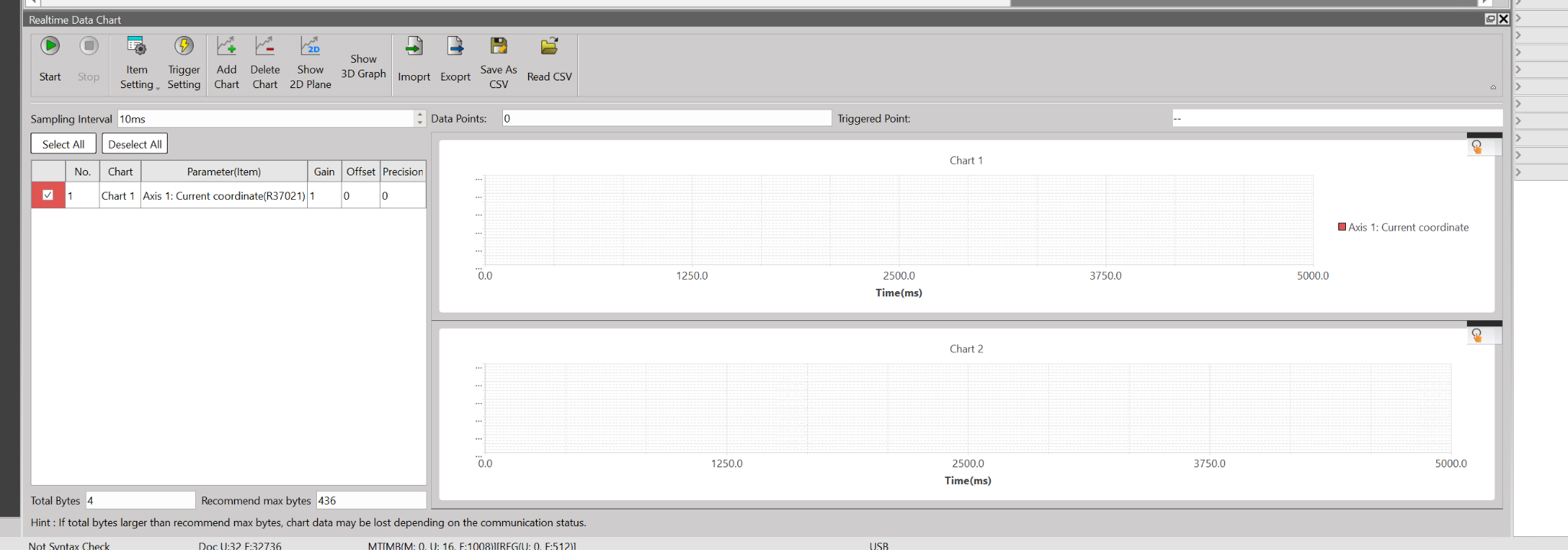
Click Add Chart to add multiple Realtime Data Charts.
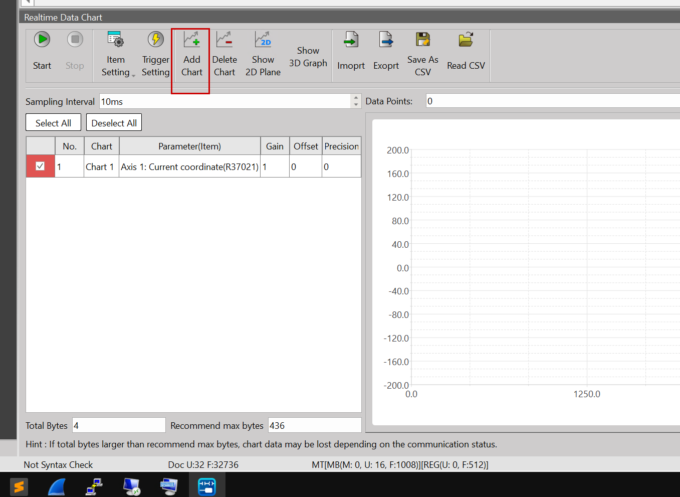
Done!
Item Settings
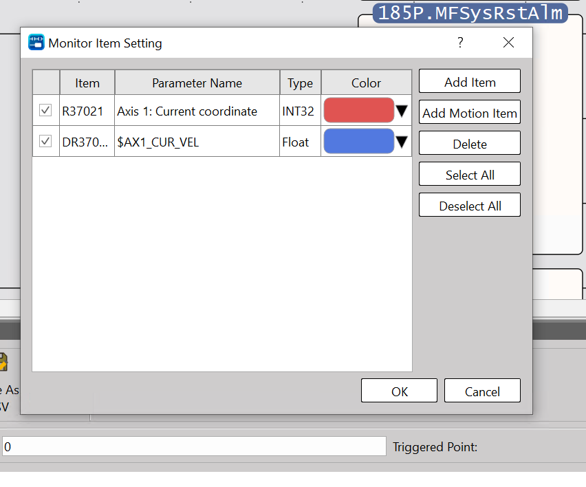
Next, you can add data to monitor in Item Settings.
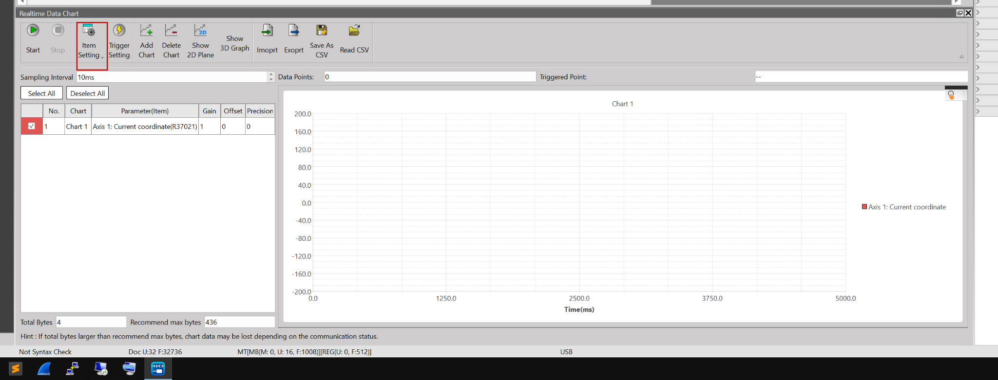
This is the settings screen for the monitored data.
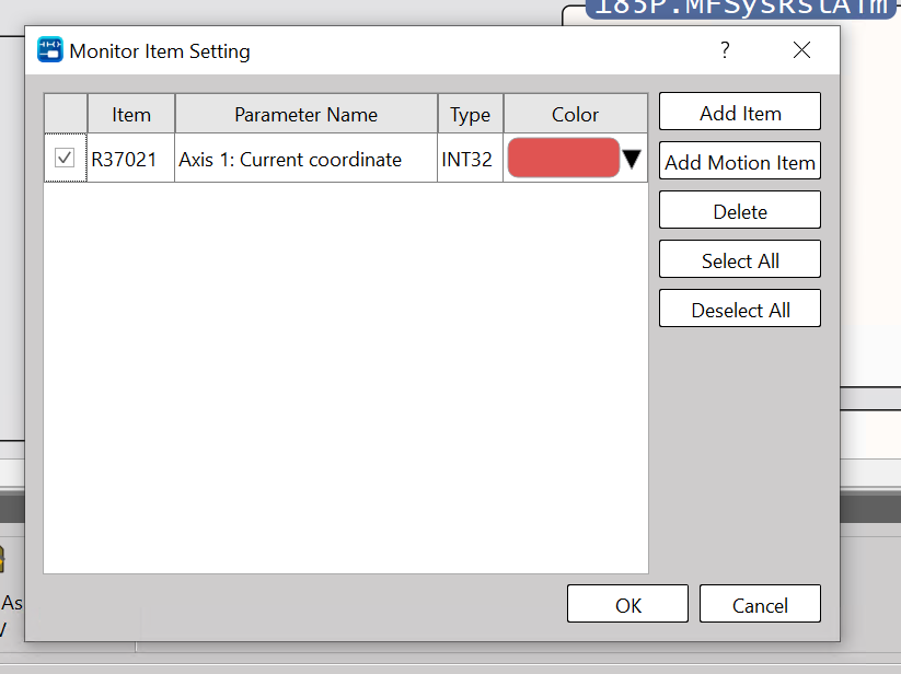
Add monitoring items using Add Item.
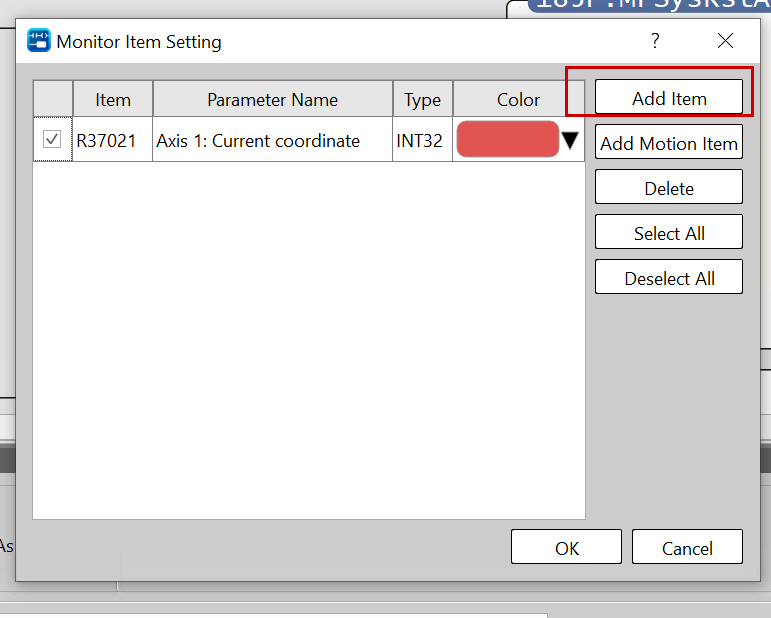
The item’s additional settings screen appears. Click the … button next to Name.
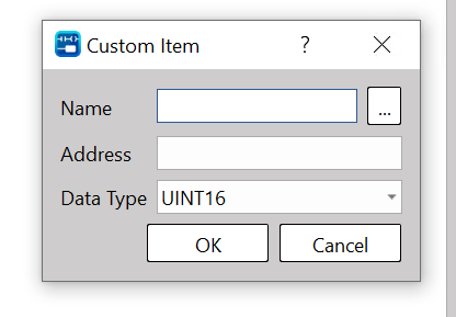
The device settings screen will appear.
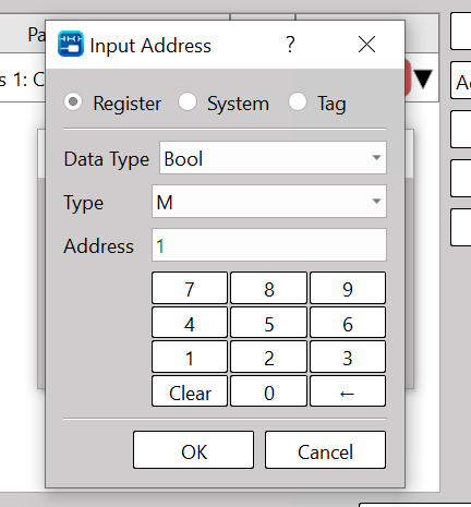
Select System.
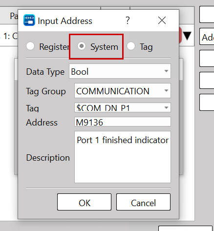
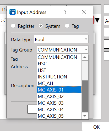
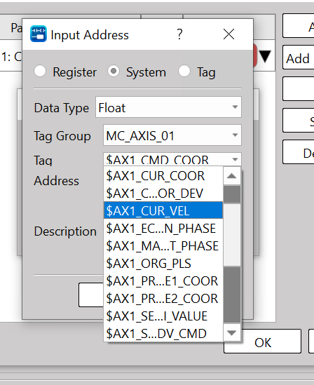
This time, since we want to monitor the data for Axis 1, click Group→MC_AXIS_01.
Here you can add Boolean type data for Axis 1.
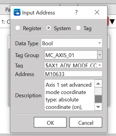
Of course, you can monitor not only Boolean variables but also axis variables such as Float types.
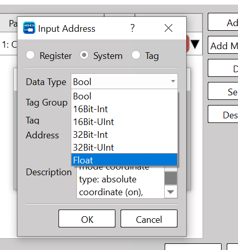
This time, we will monitor the current speed of Axis 1.
Finally, click OK to add the item.
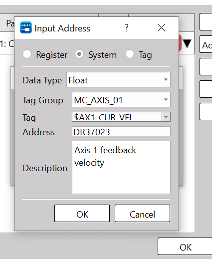
Finally, click OK.
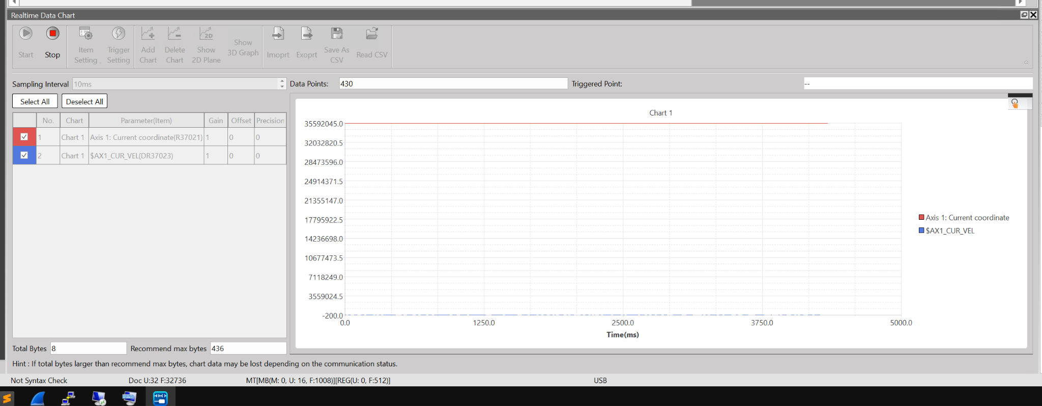
Start to view
Next, click the Start button to monitor the current position and speed of Axis 1.
Done!Finally, click the Stop button to stop monitoring the data.
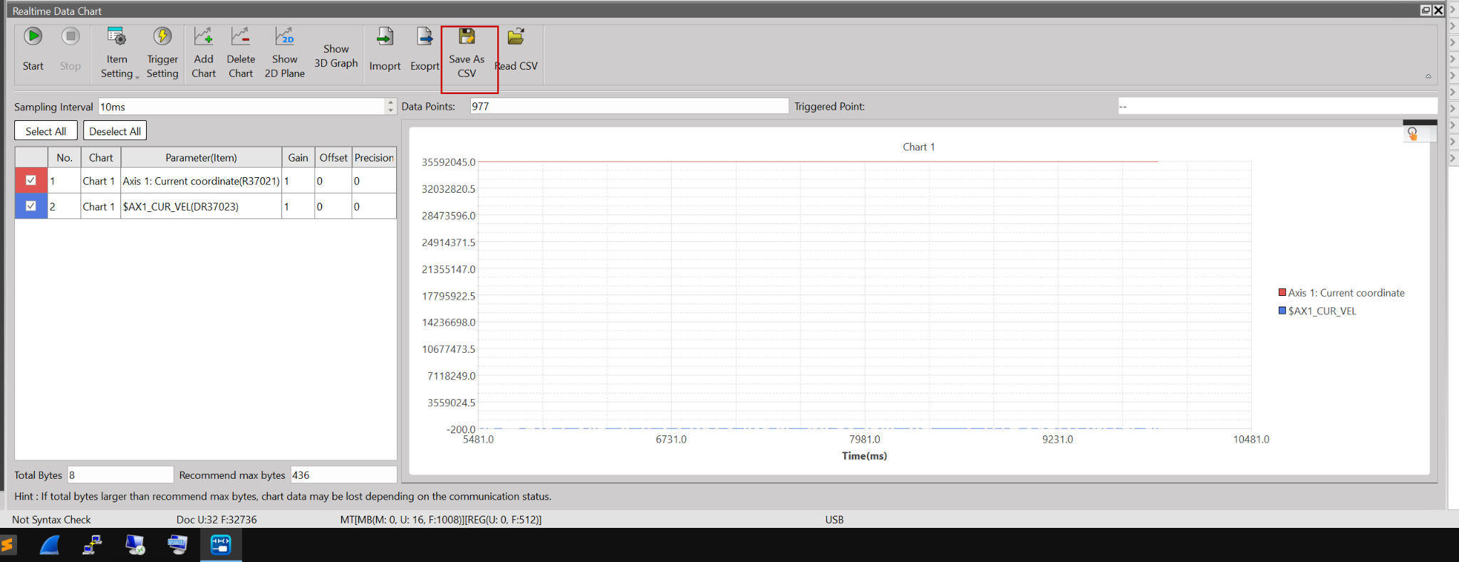
Save as CSV
Click the Save as CSV button to save the retrieved data as a CSV file.
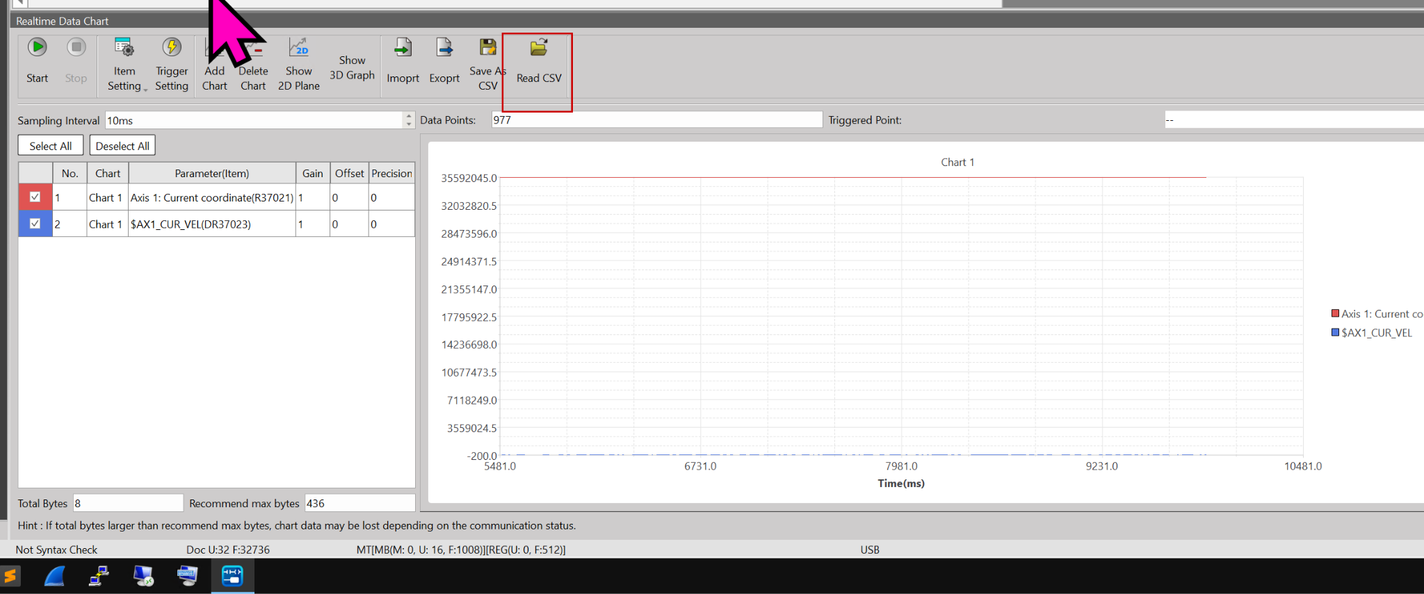
Read CSV
Click the “Read as CSV” button to import the retrieved data into a CSV file using UperLogic and view it.
Import/Export Settings
Additionally, by clicking Import/Export Settings, you can reuse the settings for this Realtime Data Chart.
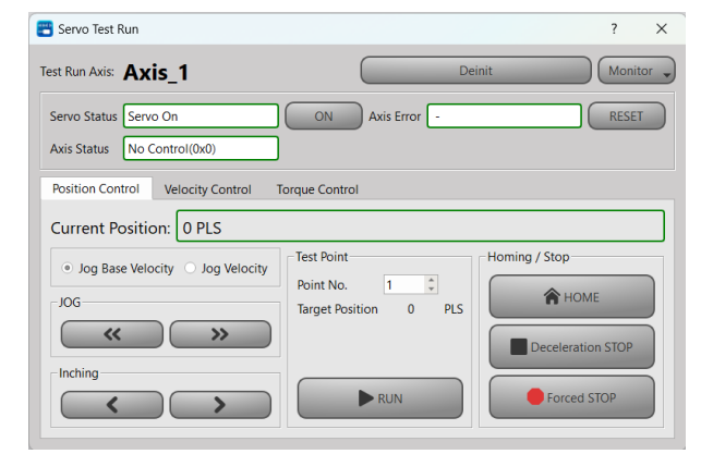
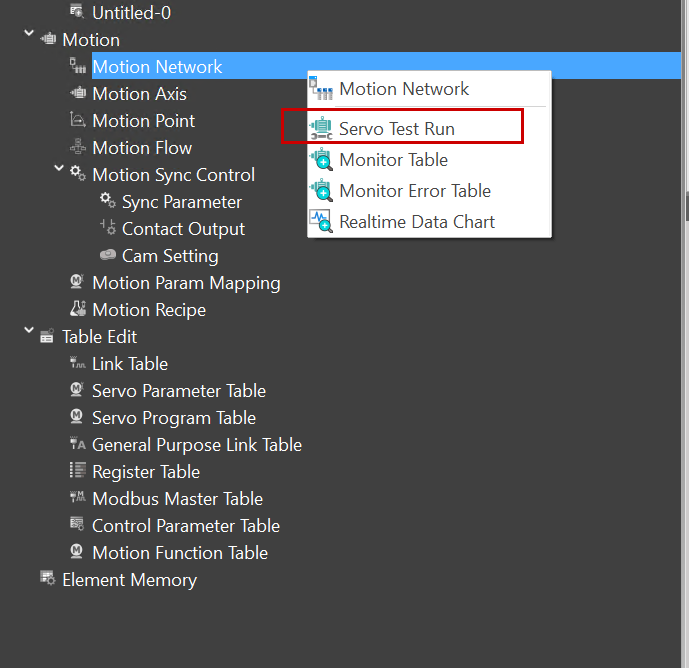
Test Run!
最後はTest Runを実施します。Motion→Motion Network→Servo Test Runをクリックします。
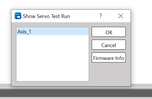
Select the axis you want to operate on for the Test Run → Proceed by clicking OK.
This is the Test Run operation screen.
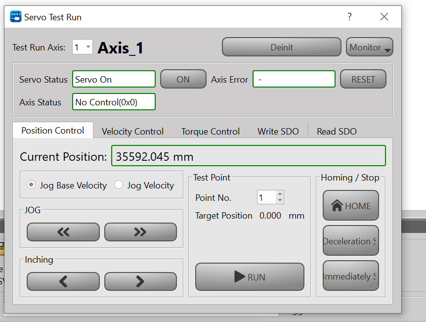
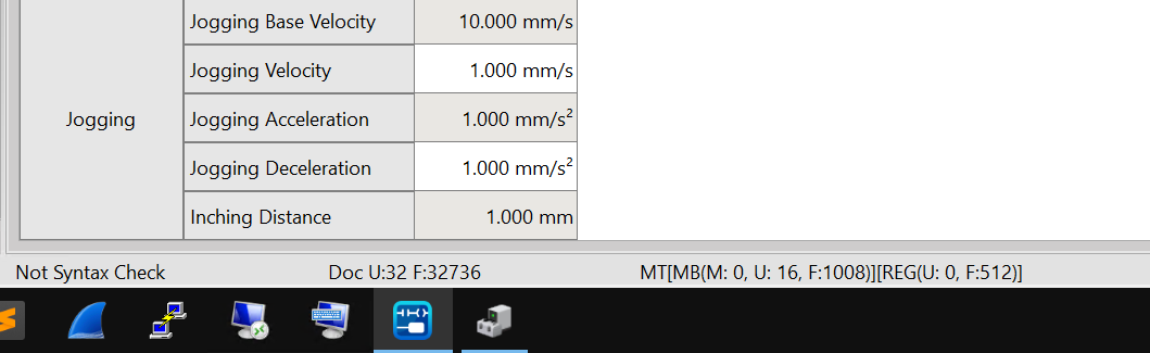
The Jog Speed setting can be configured from Motion Axis → Jogging.
You can verify the operation from this video.