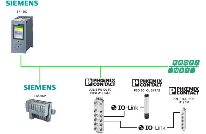
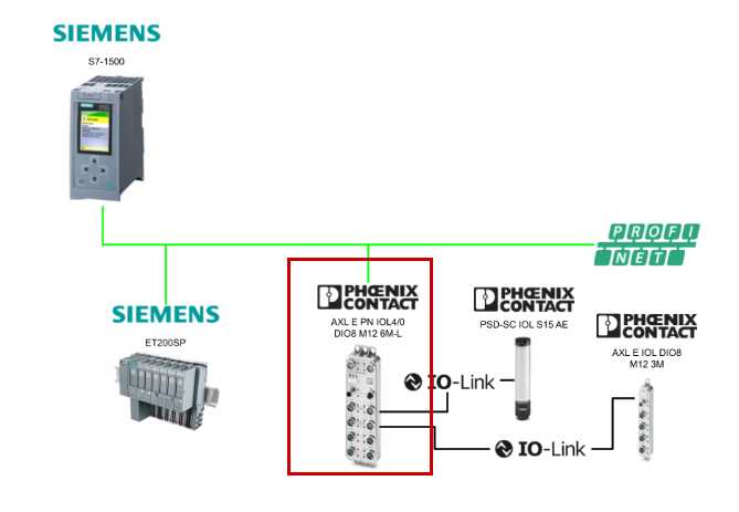
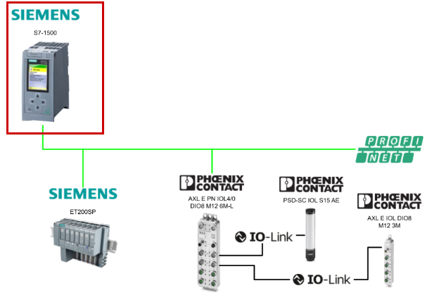
This article explains the procedure for connecting the Siemens S7-1500 and the Phoenix Contact AXL E PN IOL4/0 DIO8 M12 6M-L via Profinet. The following is the IO-Link device used in this setup:
- AXL E IOL DIO8 M12 3M
- PSD-SC IOL S15 AE
Alright, let’s enjoy the FA!
Foreword
Thank you from the bottom of my heart for visiting my technical blog and YouTube channel.
We are currently running the “Takahashi Chris” radio show with Full-san (full@桜 八重 (@fulhause) / X) which I deliver every Wednesday night.
Sharing, not hoarding, technical knowledge
We publish technical information related to factory production technology and control systems for free, through blogs and videos.
With the belief that “knowledge should be accessible to everyone,” we share practical know-how and real-world troubleshooting cases from our own field experience.
The reason we keep it all free is simple: to help reduce the number of people who struggle because they simply didn’t know.
If you’ve ever thought:
- “Will this PLC and device combination actually work?”
- “I’m having trouble with EtherCAT communication—can someone test it?”
- “I want to try this remote I/O, but we don’t have the testing environment in-house…”
Feel free to reach out!If lending equipment or sharing your configuration is possible, we’re happy to verify it and share the results through articles and videos.
(We can keep company/product names anonymous if requested.)
How can you support us?
Currently, our activities are nearly all unpaid, but creating articles and videos takes time and a proper testing environment.If you’d like to support us in continuing and expanding this content, your kind help would mean a lot.
Membership (Support our radio show)
This support plan is designed to enhance radio with Mr Full.
https://note.com/fulhause/membership/join
Amazon Gift List (equipment & books for content production)
Lists equipment and books required for content creation.
https://www.amazon.co.jp/hz/wishlist/ls/H7W3RRD7C5QG?ref_=wl_share
Patreon (Support articles & video creation)
Your small monthly support will help to improve the environment for writing and verifying articles.
https://www.patreon.com/user?u=84249391
Paypal
A little help goes a long way.
https://paypal.me/soup01threes?country.x=JP&locale.x=ja_JP
Just trying to share things that could’ve helped someone—if only they’d known.
Your support helps make knowledge sharing more open and sustainable.
Thank you for being with us.
soup01threes*gmail.com
Technical knowledge shouldn’t be kept to ourselves.
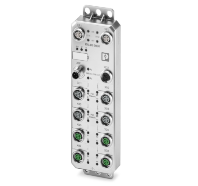
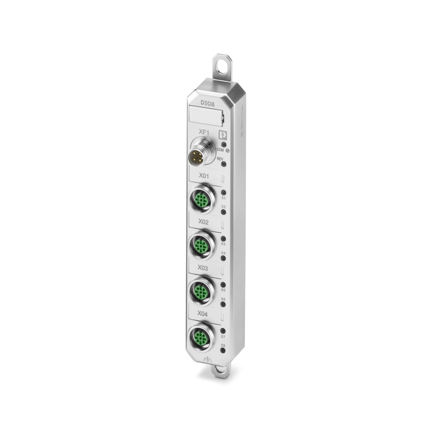
AXL E PN IOL4/0 DIO8 M12 6M-L?
The Axioline E device is designed for use within a PROFINET network and enables the operation of up to four IO-Link sensors and actuators. In addition, the Axioline E device supports the acquisition and output of digital signals. It is also suitable for use without a control cabinet in harsh industrial environments.
Features
Here are the main specifications of the Axioline E device.
- Connection via M12 connectors supporting push-pull quick-connect or screw-type connections;
- Mapping as a PROFINET device compliant with PROFINET Specification V2.4 (Conformance Class C (IRT Switch));
- Supports PROFINET system redundancy S2;
- PROFINET support with a minimum cycle time of 1 ms
- IO-Link specification V1.1.2
- Two Ethernet ports (with integrated switch)
- Data transfer rate: 100 Mbps
- Short-circuit and overload protection
- Protection rating: IP65/IP67/IP69
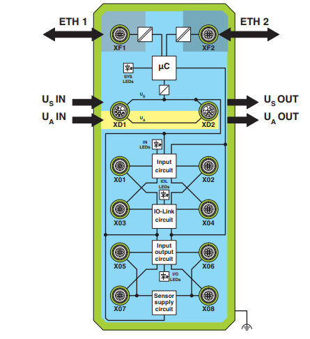
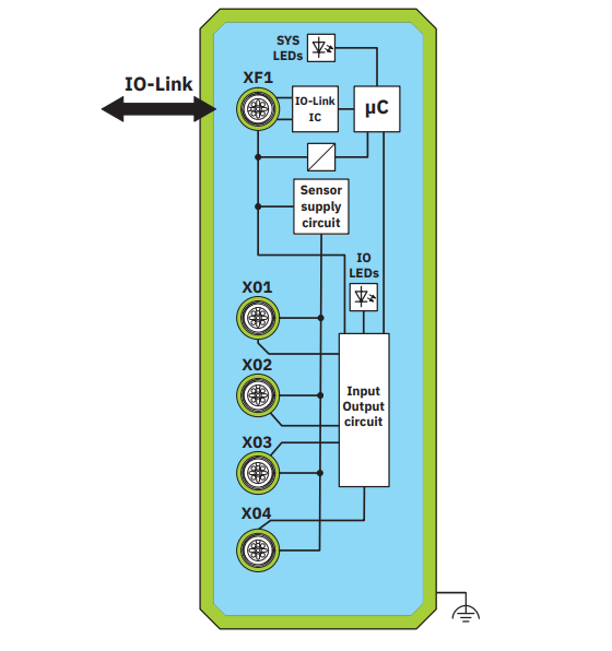
Internal Circuit Diagram
This shows the internal wiring of the Axioline E device connector.
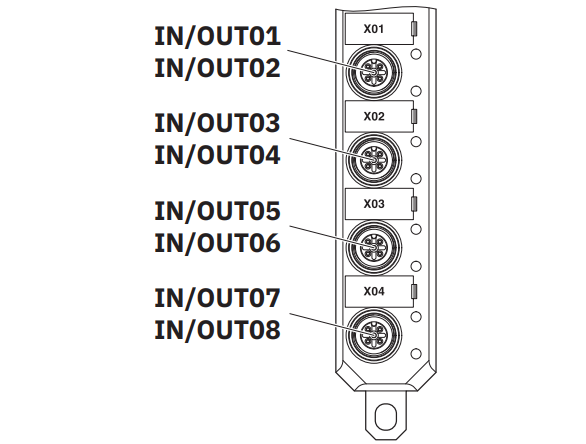
Connecting IO-Link Ports and Digital I/O
Here is the connection diagram for the IO-Link port and DIDO on the Axioline E device.
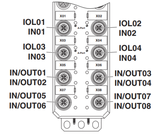
Connection | Name | Meaning |
|---|---|---|
X01 … X04 | IN01 … IN04 | Input1 … 4(Pin2) |
IOL01 … IOL04 | IO-Link A PORT1 … 4 | |
X05 … X08 | IN/OUT01 … IN/OUT08 | In/Out1 … 8 |
Pin Assignments for the US/UA Power Supply
This is the pinout and L-code for the Axioline E device power supply.
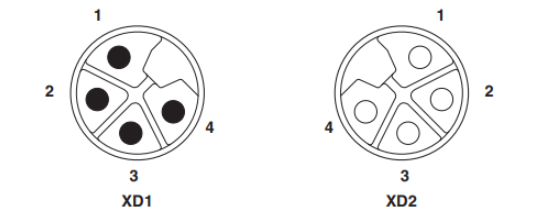
ピン | IN (XD1) | OUT (XD2) | Wire color |
|---|---|---|---|
1 | +24 V DC (U_S) | +24 V DC (U_S) | Blown |
2 | GND (U_A) | GND (U_A) | White |
3 | GND (U_S) | GND (U_S) | Green |
4 | +24 V DC (U_A) | +24 V DC (U_A) | Black |
Factory Setting
The following features and settings are available in the default configuration at the time of shipment.
PROFINET
項目 | 値 |
|---|---|
Device name | No name assigned(Name not yet assigned) |
IP address | 0.0.0.0 |
Subnet mask | 0.0.0.0 |
Default Gateway | 0.0.0.0 |
Device designation | AXL E PN IOL4/0 DIO8..-L |
Vendor ID | 00B0hex |
Device ID | 0180hex |
AXL E IOL DIO8 M12 3M – Digital module
このAxioline Eデバイスは、IO-Link Aポートを介してIO-Linkマスターに接続することができます。このデバイスを使用することで、IO-Link経由でデジタル信号の取得と出力が可能になります。また、IO-Linkマスターを介することで、さまざまなネットワーク内での使用にも対応しています。
Features
- Connection to the IO-Link master via an M12 connector (Code A, 4-pin)
- Type A port
- Compliant with IO-Link specification V1.1.3
- Up to 8 I/O connections via M12 connector (Code A, 5-pin)
- Diagnostics and status indicators
- Single-channel diagnostics
- Short-circuit and overload protection for sensor power supply
- Built-in device nameplate data
- Protection rating IP65/IP67/IP69
Layout
Here is the layout of the AXL E IOL DIO8 M12 3M.
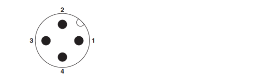
Pin layout
Pin | IO-Link Port A (XF1) |
|---|---|
1 | +24 V DC (L+) |
2 | Unused |
3 | GND (L-) |
4 | C/Q、IO-Link data transmission channel |
Be careful not to damage the sensor. When using a channel as an input, do not configure it as an output. Doing so may damage the connected sensor. Use each channel as either an input or an output.
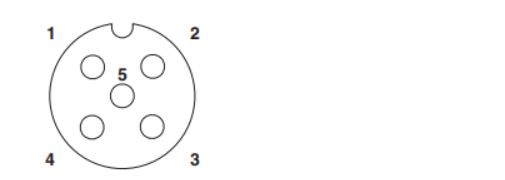
Pin | X01 … X04 |
|---|---|
1 | +24 V DC (L+) |
2 | Inputs/Outputs: 2, 4, 6, 8 |
3 | GND (L-) |
4 | Inputs/Outputs 1, 3, 5, 7 |
5 | Functional grounding |
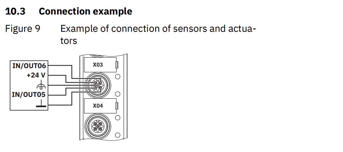
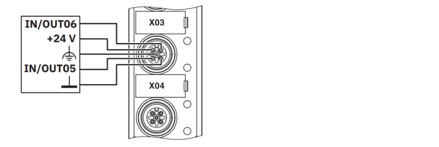
Wiring Example
This is a wiring example for the AXL E IOL DIO8 M12 3M.
In-process data
Digital input
Byte | 0 | ||||||
|---|---|---|---|---|---|---|---|
Bit | 7 | 6 | 5 | 4 | 3 | 2 | 1 |
LED | 08 | 07 | 06 | 05 | 04 | 03 | 02 |
Port | X04 | X03 | X02 | X01 | |||
Pin | 2 | 4 | 2 | 4 | 2 | 4 | 2 |
Signal | IN08 | IN07 | IN06 | IN05 | IN04 | IN03 | IN02 |
Device status data
Byte | 1 | ||||||
|---|---|---|---|---|---|---|---|
Bit | 7 | 6 | 5 | 4 | 3 | 2 | 1 |
Error | Reserved | Input | Reserved | L+ | Reserved |
Byte | 2 | ||||||
|---|---|---|---|---|---|---|---|
Bit | 7 | 6 | 5 | 4 | 3 | 2 | 1 |
Error | Digital Output Overload OR Short Circuit | ||||||
Port | X04 | X03 | X02 | X01 | |||
Pin | 2 | 4 | 2 | 4 | 2 | 4 | 2 |
Signal | OUT08 | OUT07 | OUT06 | OUT05 | OUT04 | OUT03 | OUT02 |
Byte | Bit | Error | Meaning |
|---|---|---|---|
1 | 7 … 4 | Reserved | Reserved |
3 | Input | 0: No error in the sensor power supply for digital inputs | |
1: Overload/short circuit in the sensor power supply for digital inputs | |||
2 | Reserved | Reserved | |
1 | L+ | 0: No low voltage on L+ | |
1: Low voltage to L+ | |||
0 | Reserved | Reserved | |
2 | 7 … 0 | Output | 0: No errors in the digital output |
1: Overload/short circuit at OUTxx |
OUT Process Data
Digital output
Byte | 0 | ||||||
|---|---|---|---|---|---|---|---|
Bit | 7 | 6 | 5 | 4 | 3 | 2 | 1 |
LED | 08 | 07 | 06 | 05 | 04 | 03 | 02 |
Port | X04 | X03 | X02 | X01 | |||
Pin | 2 | 4 | 2 | 4 | 2 | 4 | 2 |
Signal | OUT08 | OUT07 | OUT06 | OUT05 | OUT04 | OUT03 | OUT02 |
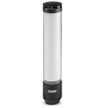
PSD-SC IOL S15 AE – Signal tower?
This signal tower is designed to indicate the status of machines and systems.
Each segment of the display surface can be individually configured for color, brightness, and lighting effects.
The signal tower can be integrated into various networks via an IO-Link master.
By integrating IODD (Device Description Files) into automation software tools such as PLCnext Engineer, you can configure signal towers centrally. Extended parameters and diagnostic data can be read from and written to the PLC on an ad-hoc basis via ISDU objects.
特長
- Versatile usage
-
4 operating modes
- Signal Tower Mode
- Auto-Scale Mode
- Fill Level Mode
- Individual Mode
- Compliant with IO-Link Specification V1.1
- Connects to an IO-Link master via an M12 connector
- Protection rating: IP66/IP69K
Type
Type | Number of segments | Voices |
|---|---|---|
PSD-SC IOL S15 AE | 15 | Yes |
PSD-SC IOL S9 AE | 9 | Yes |
PSD-SC IOL S9 | 9 | No |
Pin layout
This is the pin configuration for the M12 connector on the PSD-SC IOL S15 AE.
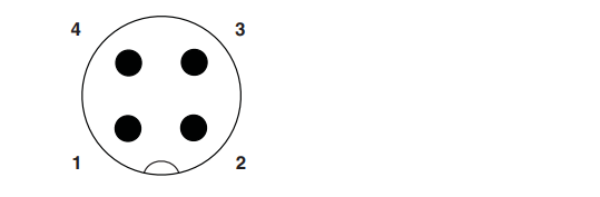
IO-Link Port A
If the current consumption exceeds 200 mA, some IO-Link masters require an external auxiliary power supply (2L+).
Pin | Features | Wire color |
|---|---|---|
1 | +24 V DC (L+) | Brown |
2 | +24 V DC (2L+)、オプション | While |
3 | GND (L-) | Blue |
4 | C/Q、IO-Linkデータ伝送チャネル | Black |
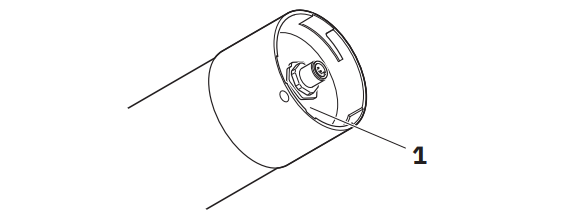
Status LED
The status LED indicates the operational status of the signal tower. The LED is located beneath the nameplate on the bottom of the signal tower.
Name | Status | Description |
|---|---|---|
Status LED | Red flashing (500 ms on, 500 ms off) | Power supply voltage present, no IO-Link communication |
Green flashing (on for 900 ms, off for 100 ms) | Power supply voltage present, IO-Link communication normal | |
OFF | Please check the power supply voltage and the connection cables. |
Process data
PSD-SC IOL S15 AE | PSD-SC IOL S9 AE | PSD-SC IOL S9 | |
|---|---|---|---|
Input process data | 0バイト | 0バイト | 0バイト |
Output process data | 3バイト | 3バイト | 2バイト |
OUT Process Data
Byte 0 | Byte 1 | Byte 2 |
|---|---|---|
Audio features | Optical functions | |
This feature is available only on devices equipped with Audio. | Individual Mode (Signal Mode) | |
Signal Tower Mode (Signal Mode) | ||
Auto-scale mode (Signal mode) | ||
Unused | Fill Level Mode (Level Mode) |
Operating Mode
The signal tower has four operating modes.
- Signal Tower Mode: Individual segments can be combined to form a single tier. This allows you to create a traditional signal tower.
- Auto-Scale Mode: Segments are automatically and evenly distributed based on the number of controlled pins and status messages. For example, if only one status message is active, the entire surface of the signal tower will light up in a single color.
- Fill Level Mode: Use segments as fill level indicators.
- Individual Mode: Each segment can be configured and controlled individually.
You can also select the operating mode using the “Signal mode” parameter.
Basic Features
You can use the optical parameters to configure the following settings for each segment.
- Color
- Lighting effect
- Brightness
These parameters allow you to freely select colors for each segment, providing maximum flexibility in choosing the lighting effect. You can also combine these parameters with one another.
For devices equipped with a siren, additional audio parameters are available. You can use these parameters to define 10 individual tones or modify 10 preset tones.
Global parameters are available on each device for general settings.
Autoscaling Mode
Auto-scale mode is the default operating mode at shipment.
In this mode, the segments of the signal tower are automatically and evenly distributed based on the number of controlled pins (bits) and the status message.
For example, if only one status message is active, the entire surface of the signal tower lights up in a single color to ensure maximum visibility.
If multiple signals are present, the illuminated area is divided proportionally. If the segments cannot be divided evenly, the color with the highest priority is assigned to the last segment or the remaining segments.
Process Data: Auto-Scale Mode
The settings use parameters from segments 1 through 5.
Bit | 15 | 14 | 13 | 12 | 11 | 10 | 9 | 8 | 7 | 6 | 5 | 4 | 3 | 2 | 1 | 0 |
|---|---|---|---|---|---|---|---|---|---|---|---|---|---|---|---|---|
– | – | – | – | – | – | – | – | – | – | – | Seg 5 | Seg 4 | Seg 3 | Seg 2 | Seg 1 |

Implementation
Now let’s actually create a project.
Phoenix Contact Side
First, we will prepare the Phoenix Contact AXL E PN IOL4/0 DIO8 M12 6M-L.
Download the GSDML file
Click the link below to download the GDSML file for the AXL E PN IOL4/0 DIO8 M12 6M-L.
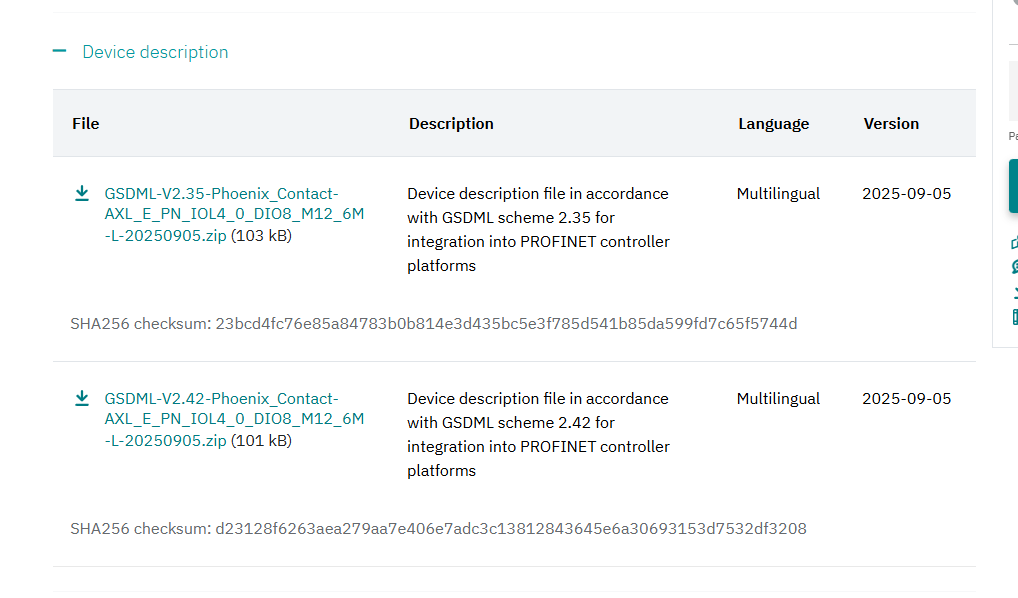
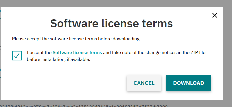
Agree to the license terms and click “Download.”
Siemens Side
Next, we will set up the Siemens side.
Install the GSDML file
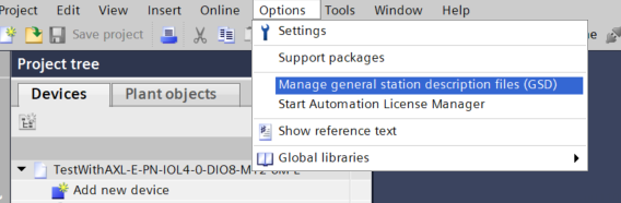
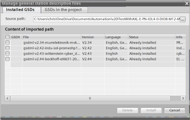
Next, click Options → Manage general station description files.
This is the GSDML File installation screen; click the … button.
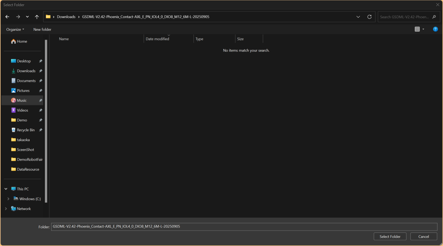
Select the folder containing the GSDML file you just downloaded.
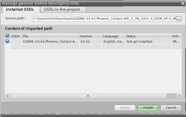
Done!Once the GSDML file is recognized, click the Install button.
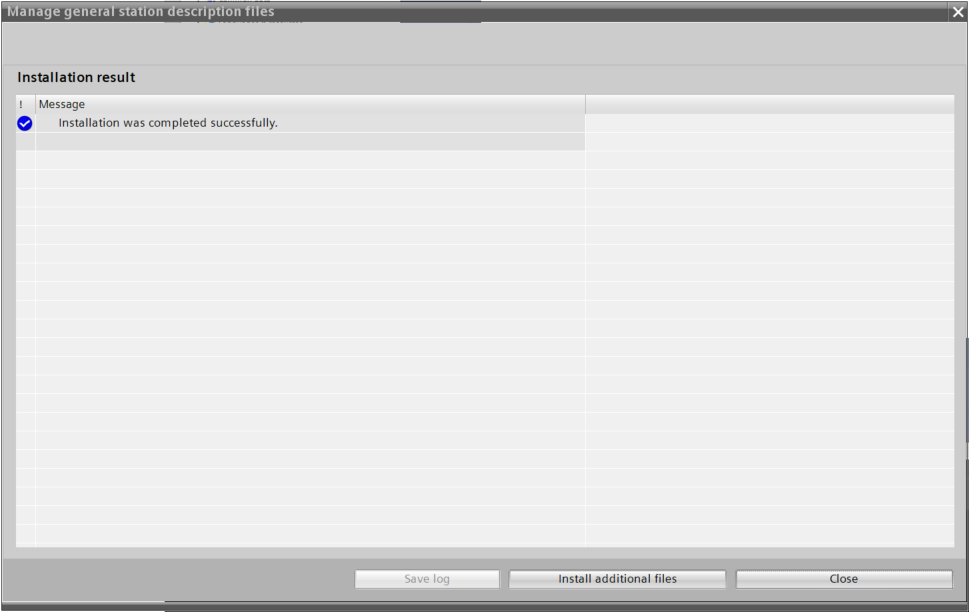
Done!The GSDML file has now been installed.
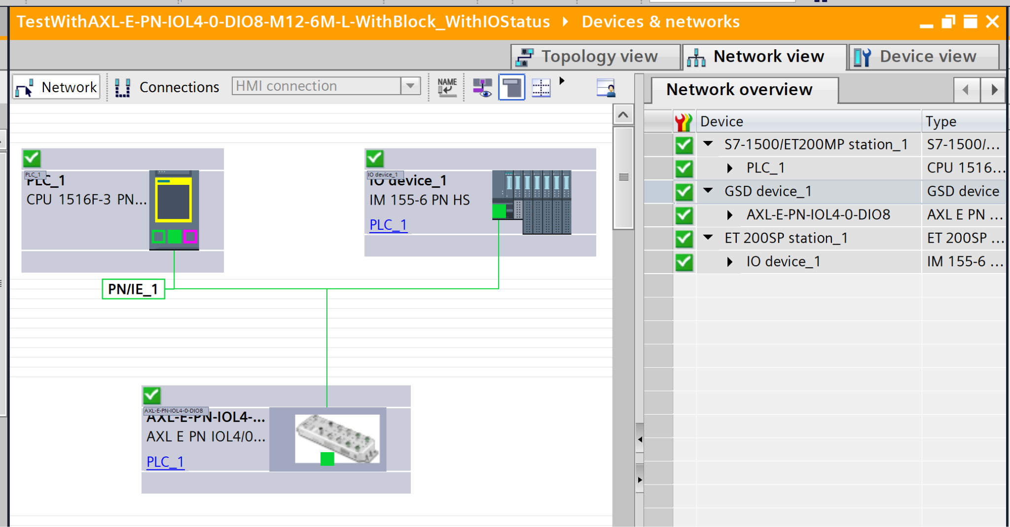
Configure Profinet Network
Next, we will set up a Profinet network.
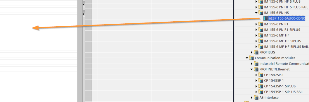
IOLINK
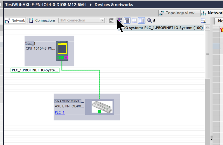
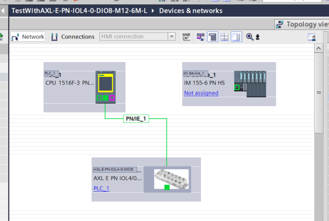
In this article, we will add the AXL E PN IOL4/0 DIO8 M12 6M-L to the Profinet network.
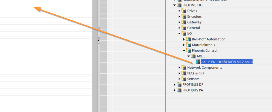
Done!AXL E PN IOL4/0 DIO8 M12 6M-L has been added.
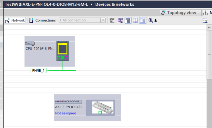
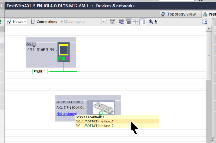
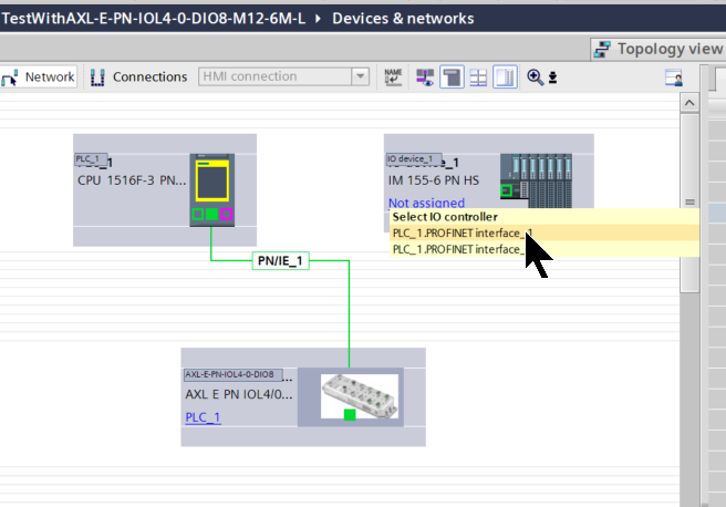
Assign a Profinet network
Click “Not assigned” next to the AXL E PN IOL4/0 DIO8 M12 6M-L entry you just added, and assign the appropriate Profient network.
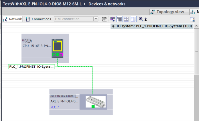
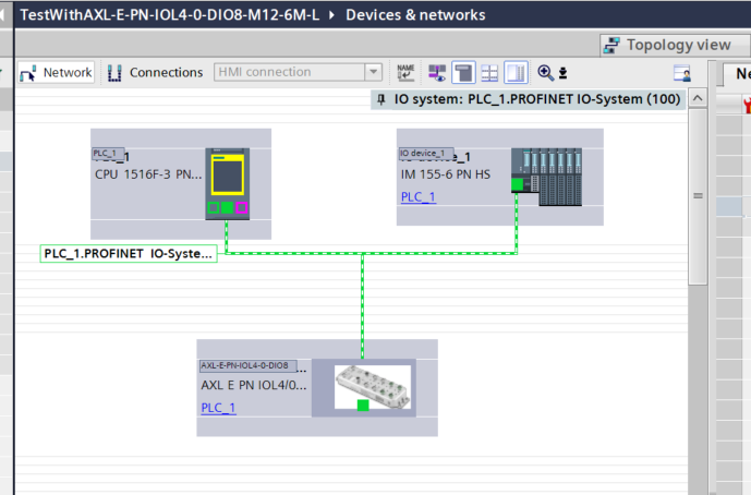
Done!
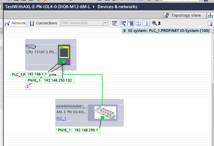
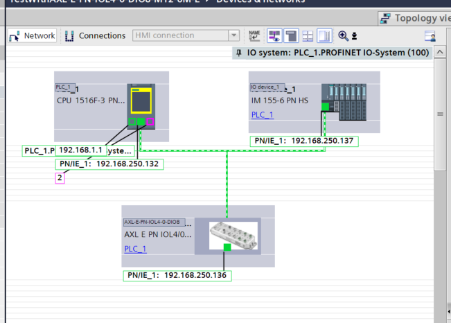
Change your IP address
Click the button shown below to display the network’s IP address.
Next, please change the IP address to match your network configuration.
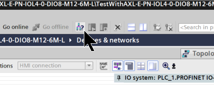
Assign an IP address to the device
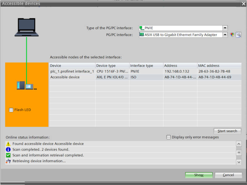
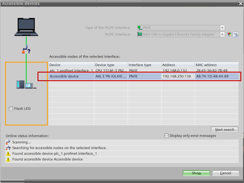
Next, click the button shown below to configure the IP address of the Profinet device.
Click “Start Search.”
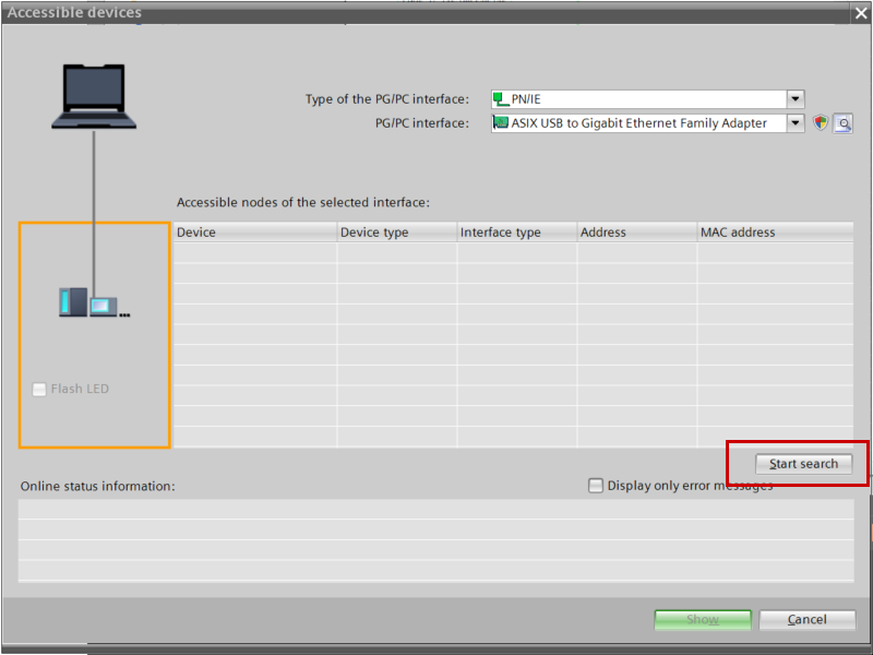
Done!Next, click the Show button.
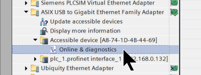
Next, click “Online & Diagnostics.”
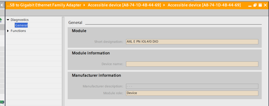
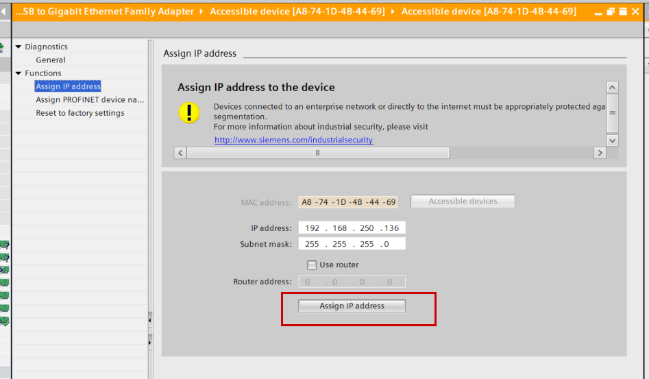
This is the diagnostic screen for the Profinet device.
Click Functions → Assign IP address.
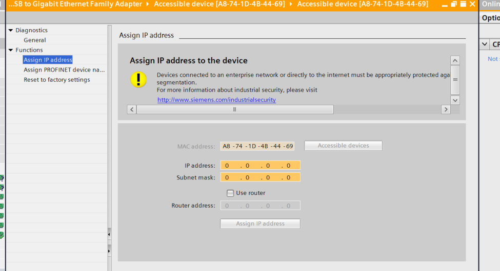
Configure the IP address according to your network configuration, then click “Assign IP address.”
Done!
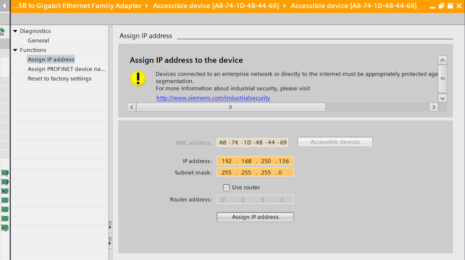
The IP address of the Profient device (AXL E PN IOL4/0 DIO8 M12 6M-L) has been changed.
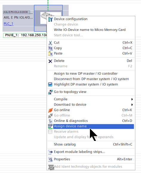
Assign a device name
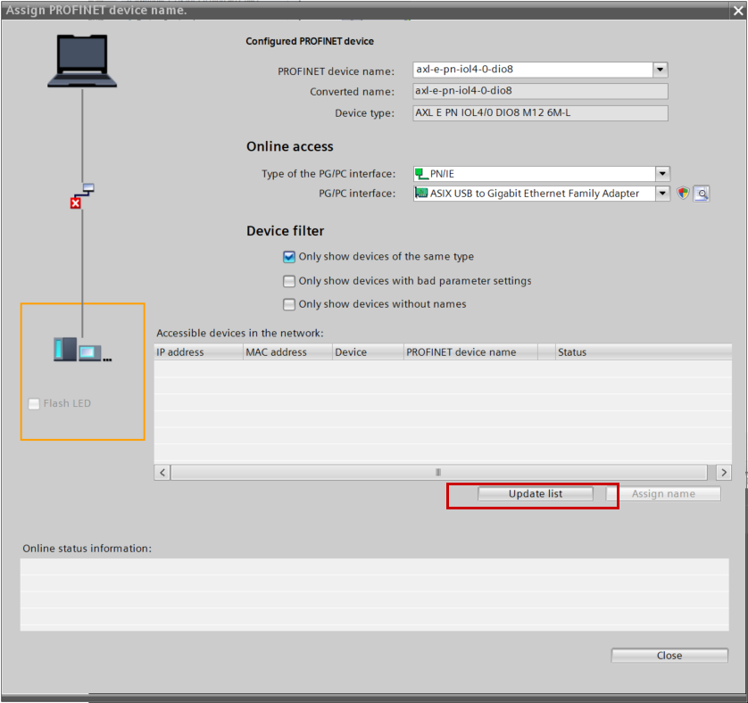
Next, to assign the device name “AXL E PN IOL4/0 DIO8 M12 6M-L,” right-click the device and select “Assign device name.”
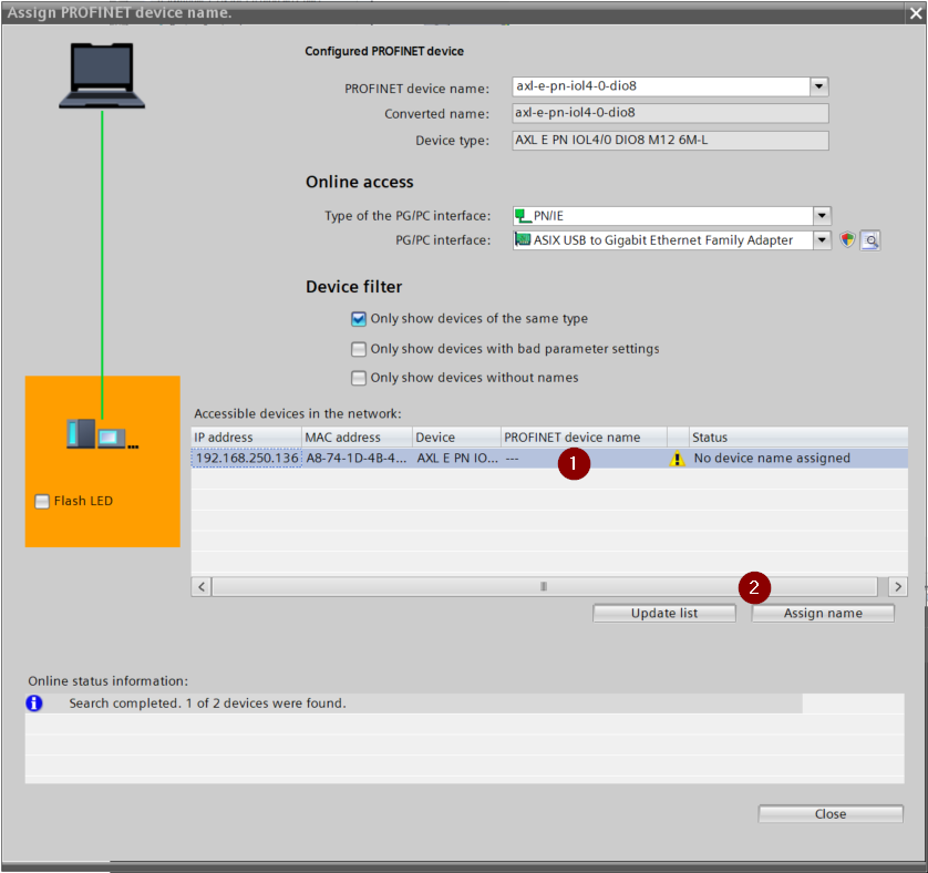
Click “Update List.”
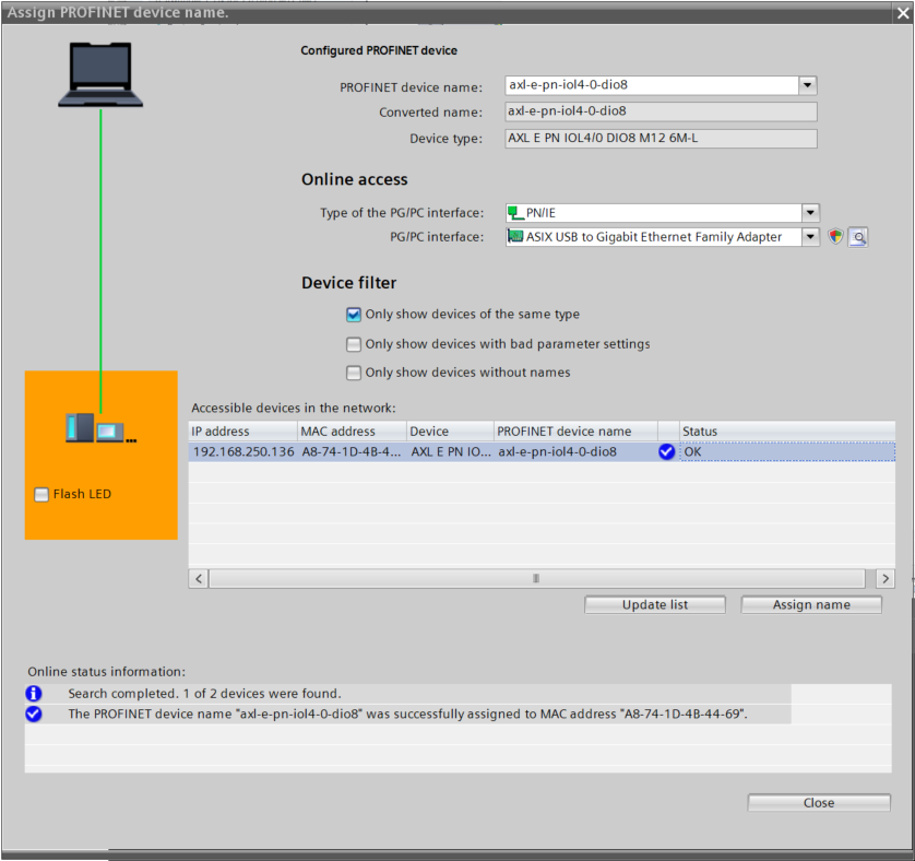
Select AXL E PN IOL4/0 DIO8 M12 6M-L, then click “Assign name.”
Done!
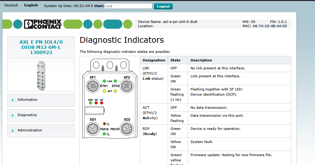
Check the web server
Next, access the AXL E PN IOL4/0 DIO8 M12 6M-L web server. By default, use the following username and password to log in to the web server:
- root,password
- fwupdater,private
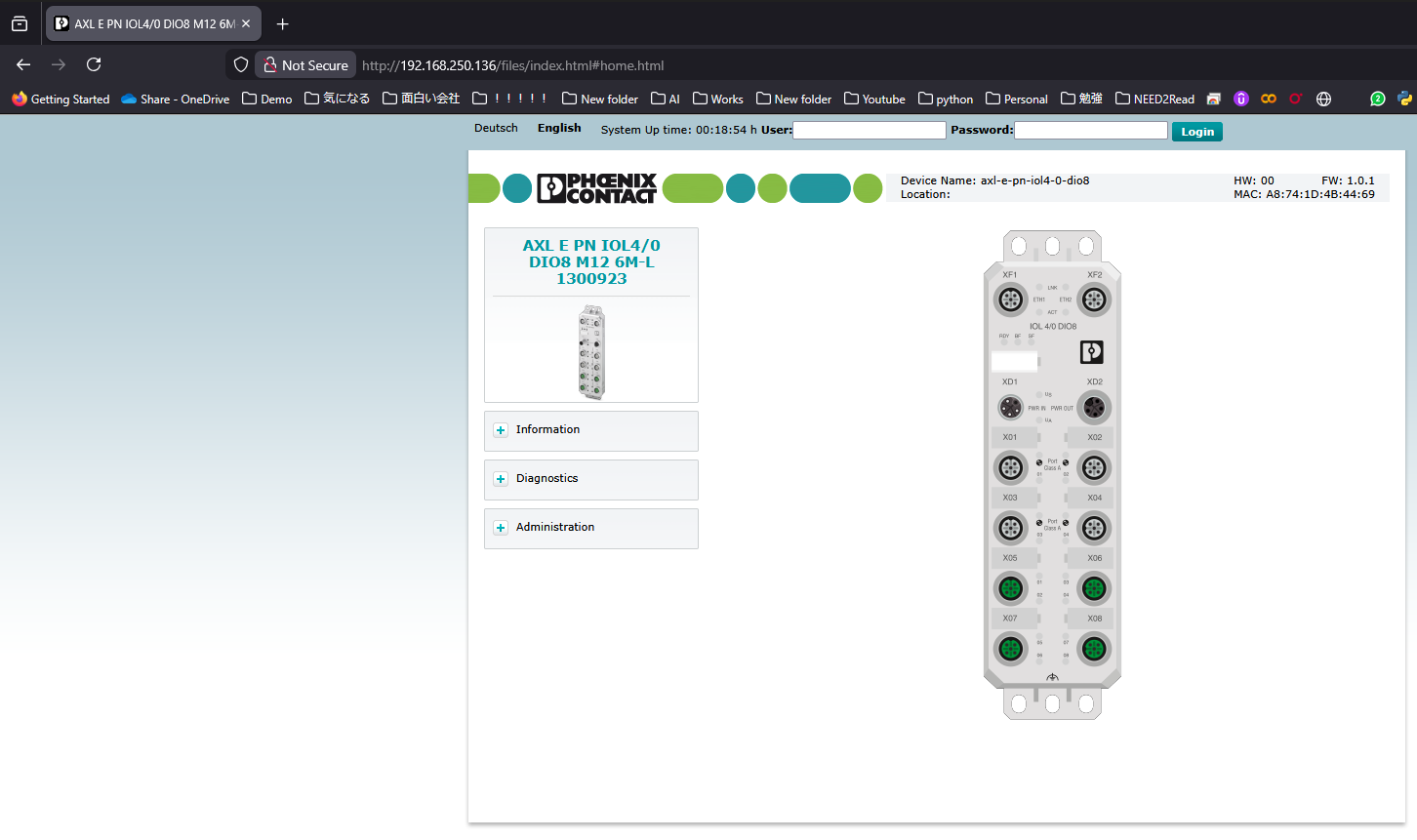
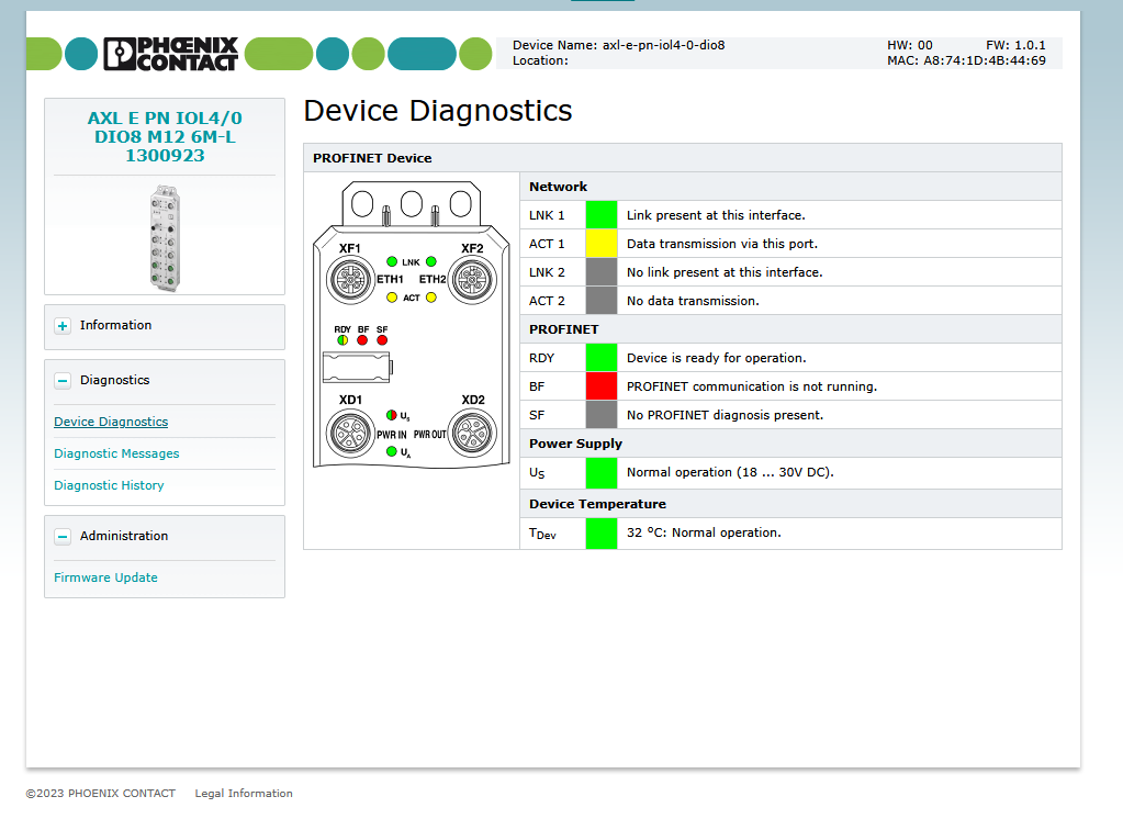
You can check the status of all LEDs via the web server.
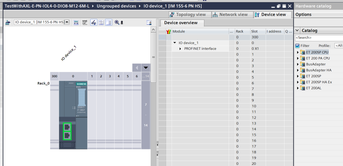
Configuring the IO-Link Slot
Next, configure the IO-Link slot for the AXL E PN IOL4/0 DIO8 M12 6M-L.
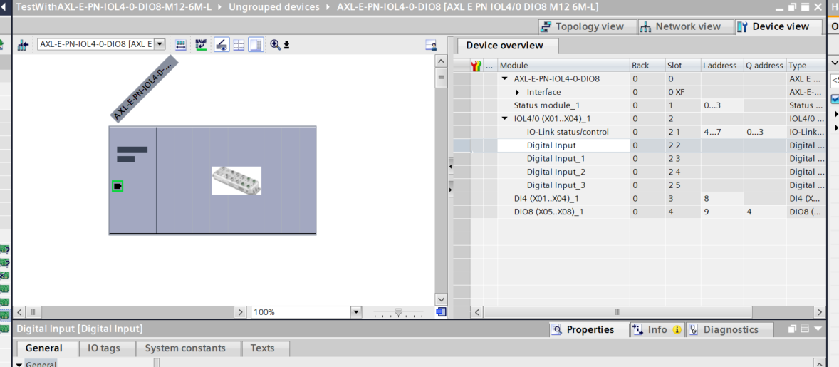
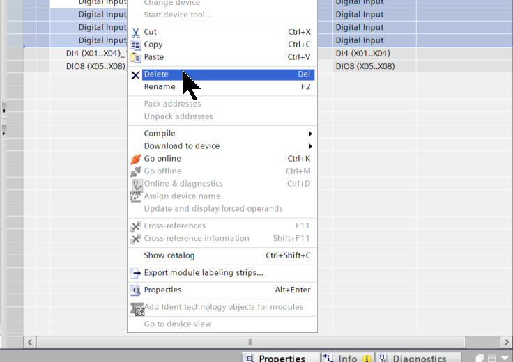
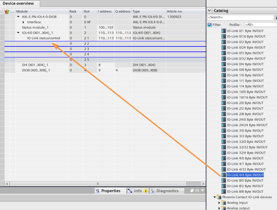
By default, all slots for the AXL E PN IOL4/0 DIO8 M12 6M-L are configured as DI. Select the four slots, right-click, and select “Delete.”
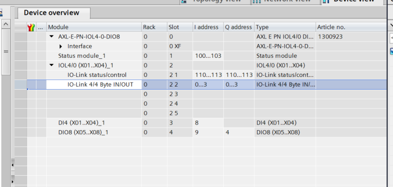
Next, add the IO-Link slot from the Catalog on the right.
Done!
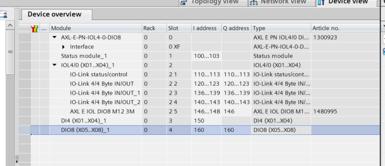
Also, since the device used in PORT4 this time is also the AXL E IOL DIO8 M12 3M from Phoenix Contact, you can add the AXL E IOL DIO8 M12 3M directly from Submodules → Digital Input/Output.
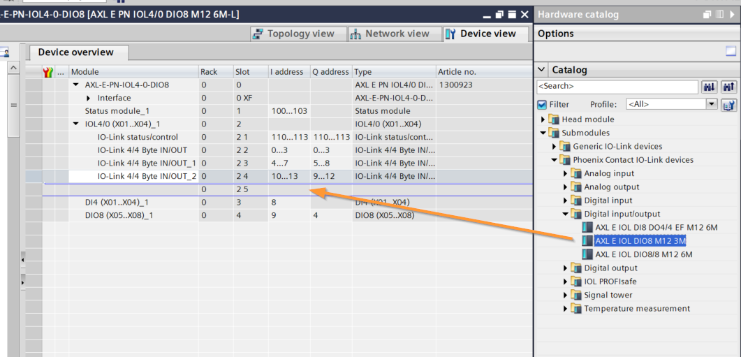
Done!
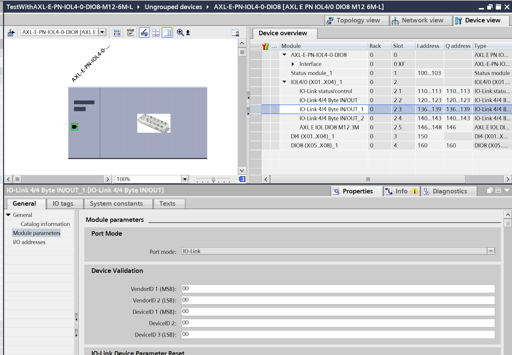
Configuring IO-Link Parameters
Next, we will configure the parameters for the IO-LINK device. Click on the PSD-SC IOL S15 AE installed on Port 2 and open Module Parameters.
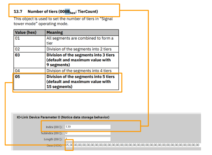
Numbers of tiers
Set the number of levels that the PSD-SC IOL S15 AE can display.
- Index=8B(HEX)=139(DEC)
- Subindex=0
- Lenght=1
- Data(HEX)=5=5 levels
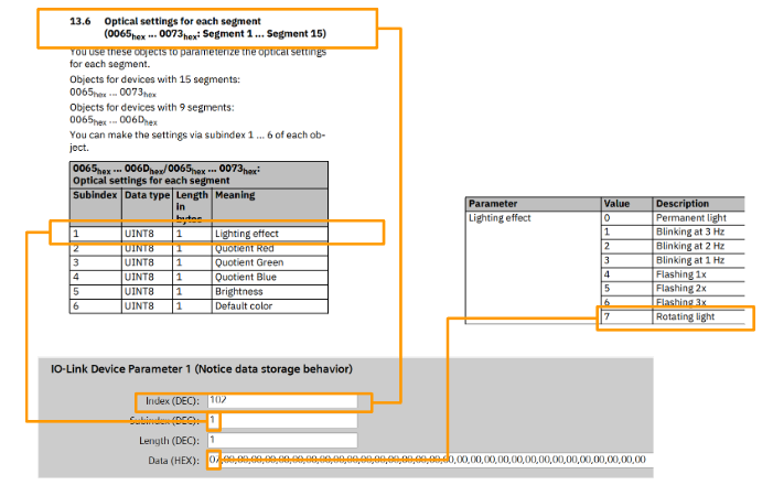
Optical Settings-Lighting Effect Segment 2
Configure the lighting effects for the PSD-SC IOL S15 AE.
- Index=66(HEX)=102(DEC)=Segment2
- Subindex=1=Lighting effects
- Lenght=1
- Data(HEX)=7=rotating beacon
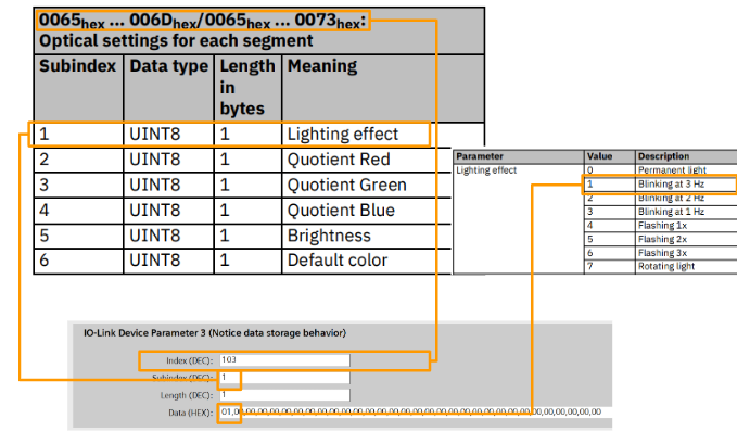
Optical Settings-Lighting Effect Segment 3
Configure the lighting effects for the PSD-SC IOL S15 AE.
- Index=67(HEX)=103(DEC)=Segment3
- Subindex=1=Lighting effects
- Lenght=1
- Data(HEX)=1=Flashing at 3 Hz
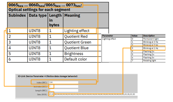
Optical Settings-Lighting Effect Segment 4
Configure the lighting effects for the PSD-SC IOL S15 AE.
- Index=68(HEX)=104(DEC)=Segment4
- Subindex=1=Lighting effects
- Lenght=1
- Data(HEX)=3=Flashing at 1 Hz
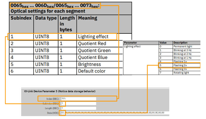
Optical Settings-Lighting Effect Segment 5
Configure the lighting effects for the PSD-SC IOL S15 AE.
- Index=69(HEX)=105(DEC)=Segment 5
- Subindex=1=Lighting effects
- Lenght=1
- Data(HEX)=5=Flashing 2x
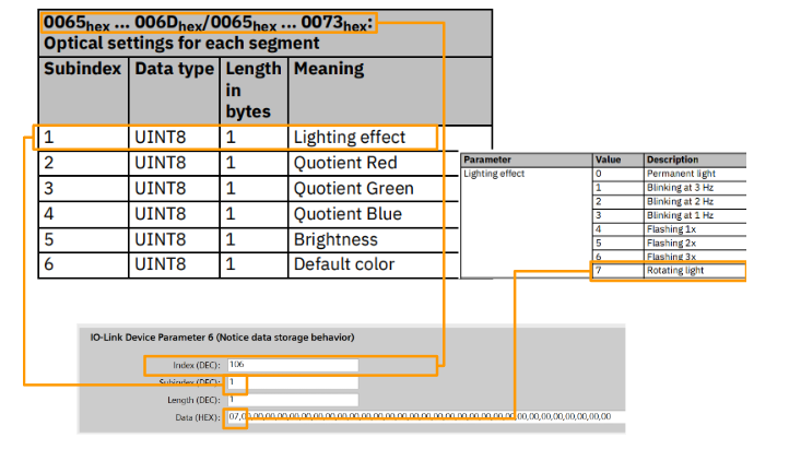
Optical Settings-Lighting Effect Segment 6
Configure the lighting effects for the PSD-SC IOL S15 AE.
- Index=6A(HEX)=106(DEC)=Segment 6
- Subindex=1=Lighting effects
- Lenght=1
- Data(HEX)=7=rotating beacon
ET200SP
Next, we will add the ET200SP Remote I/O to the Profinet network.
Done!The ET200SP has been added to the Profinet network.
Assign Profinet Network
Click “Not Assigned” and assign it to the appropriate Profinet network.
Done!
Change your IP address
Click the button shown below to display the network’s IP address, and then change the IP address to match your network.
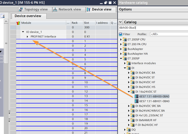
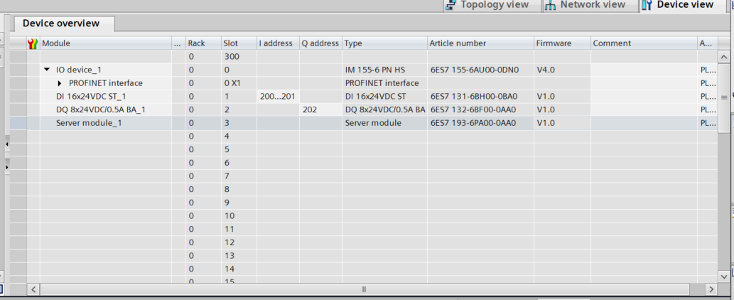
Slot Settings
Next, let’s configure the slots to match the modules actually installed on the ET200SP.
This is the DI module we’ll be using this time.
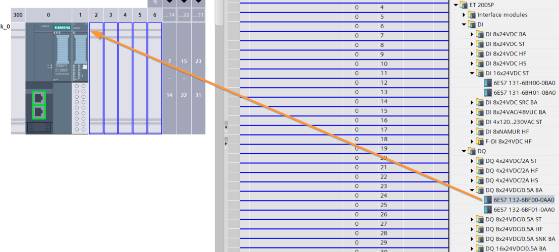
This is the DO module we’ll be using this time.
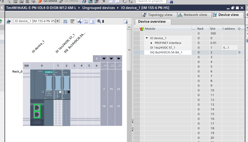
Done!
And don’t forget the Server Module!
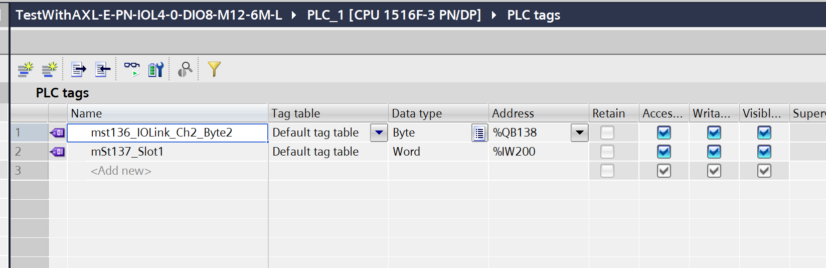
PLC Tags
These are the PLC tags defined in this article.
Program
Next, we’ll program the Siemens system.
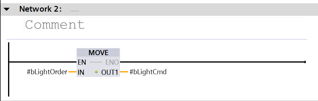
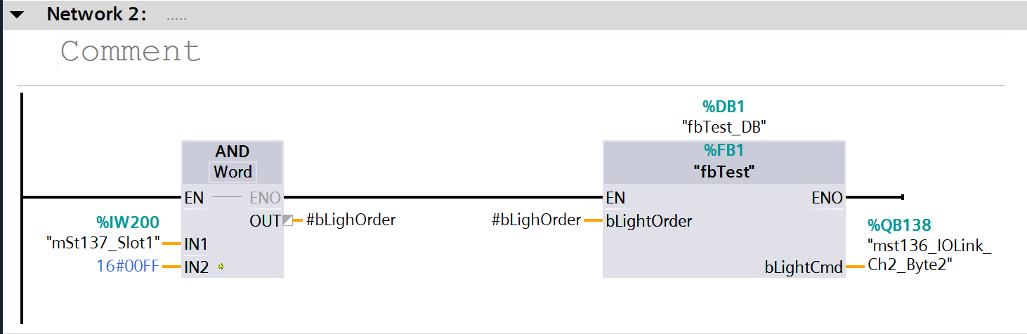
fbTest
This is a simple Facebook page for controlling the LEDs on the PSD-SC IOL S15 AE.
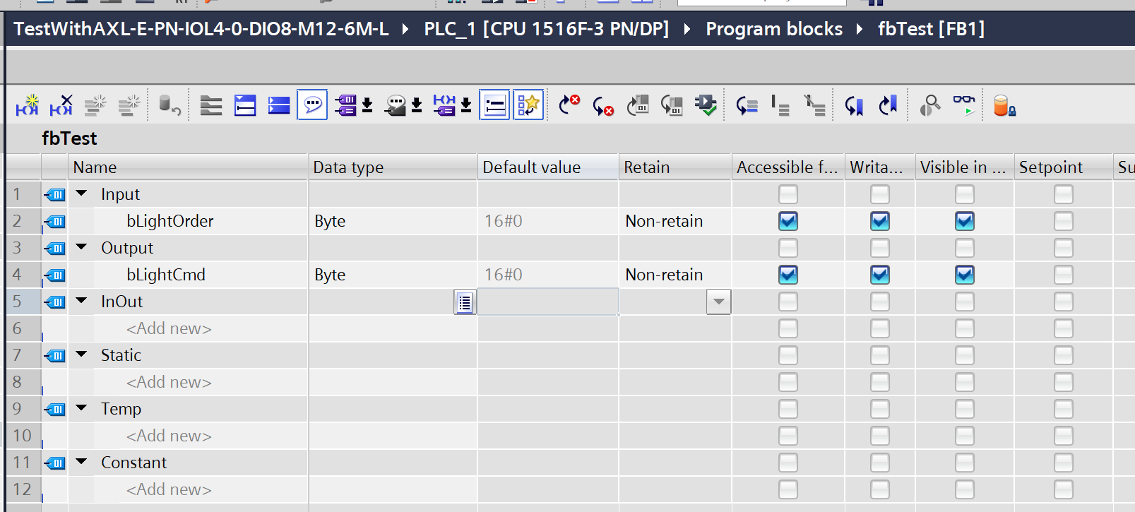
The program simply outputs the byte data exactly as it was entered.
OB1
Next, we will create the OB1 program.
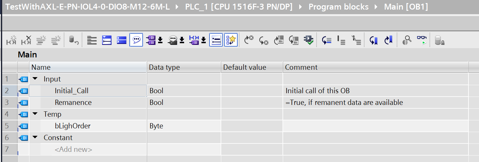
The display status of the PSD-SC IOL S15 AE changes depending on the status of the DI module installed in Slot 1 of the ET200SP.
Download
Please download the project to the S7-1500.
Results
We were able to establish Profinet communication between the Siemens PLC and the ET200SP·AXL E PN IOL4/0 DIO8 M12 6M-L.
You can see how it works in the video below.