This article describes how to set up an EtherCAT Slave using Omron’s CJ1W-ECT21 for EtherCAT communication with the Beckhoff TwinCAT 4026.
Let’s get started.
EtherCAT?
EtherCAT (Ethernet Control Automation Technology) is a high-performance industrial network system based on Ethernet that enables faster and more efficient communication, with each node transmitting Ethernet frames at high speed and short communication cycle times.
Although EtherCAT is a proprietary communication protocol, standard Ethernet technology is used for the physical layer, allowing Ethernet cables to be used in a wider range of applications.
In addition, EtherCAT can be used not only in large control systems, where high processing speeds and system integrity are required, but also in small and medium-sized control systems.

How it Works?
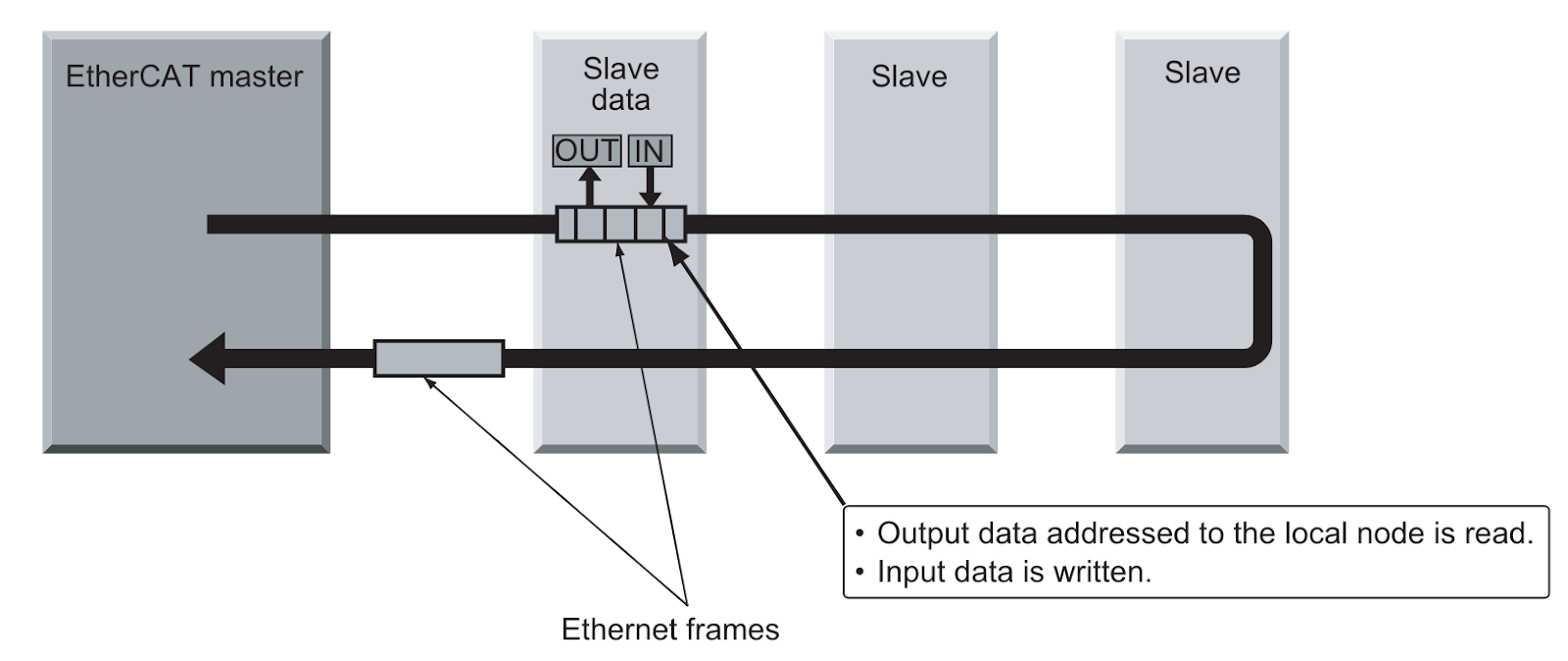
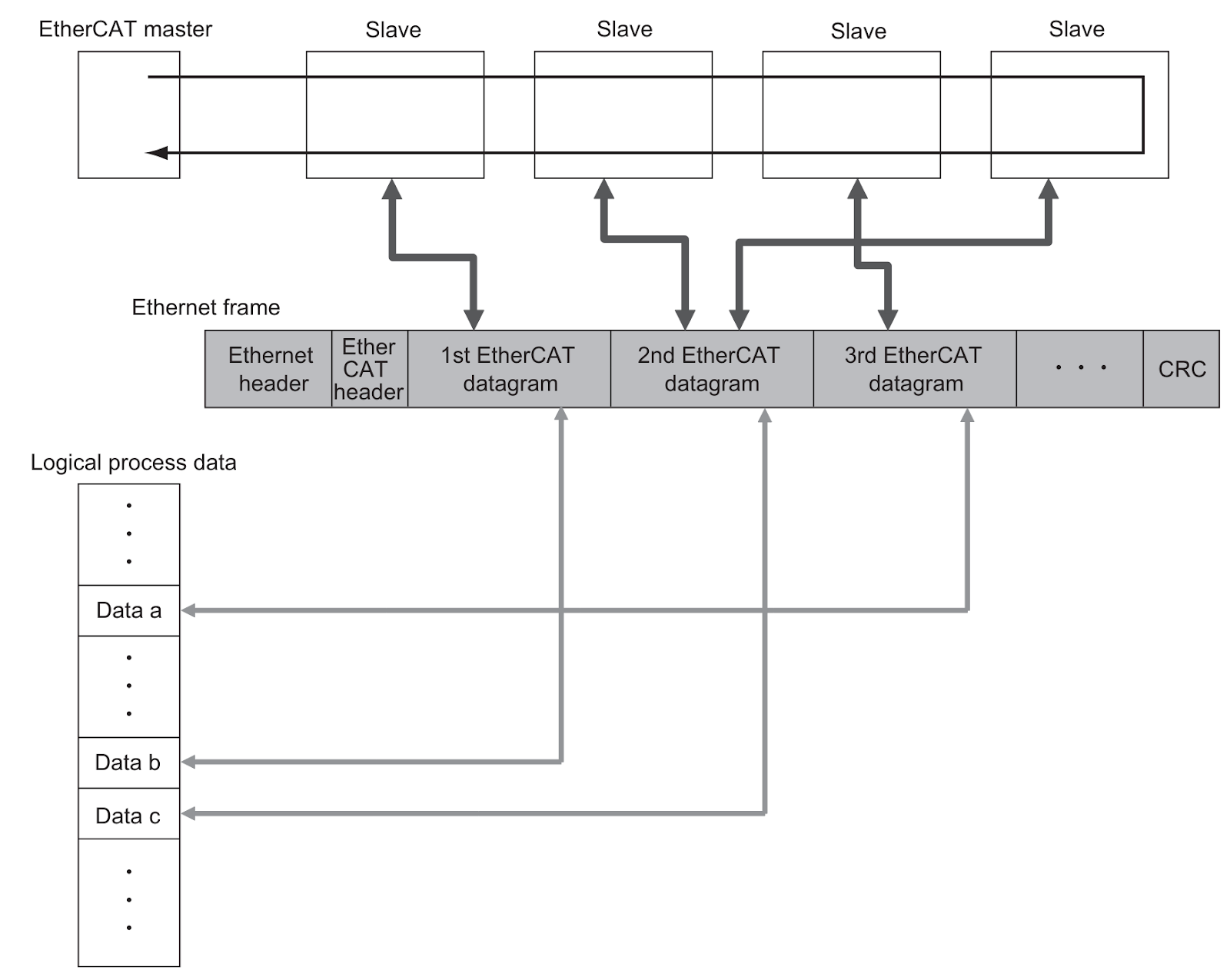
With EtherCAT, the Ethernet frame passes through all slave nodes, which can read and write data in the allocated area within the frame in a few nanoseconds.
Ethernet frames sent by the EtherCAT master pass through all EtherCAT slaves without stopping, so that the last slave sends back all frames, which then pass through all slaves again and are sent back to the EtherCAT master.
This mechanism ensures fast, real-time data transmission.
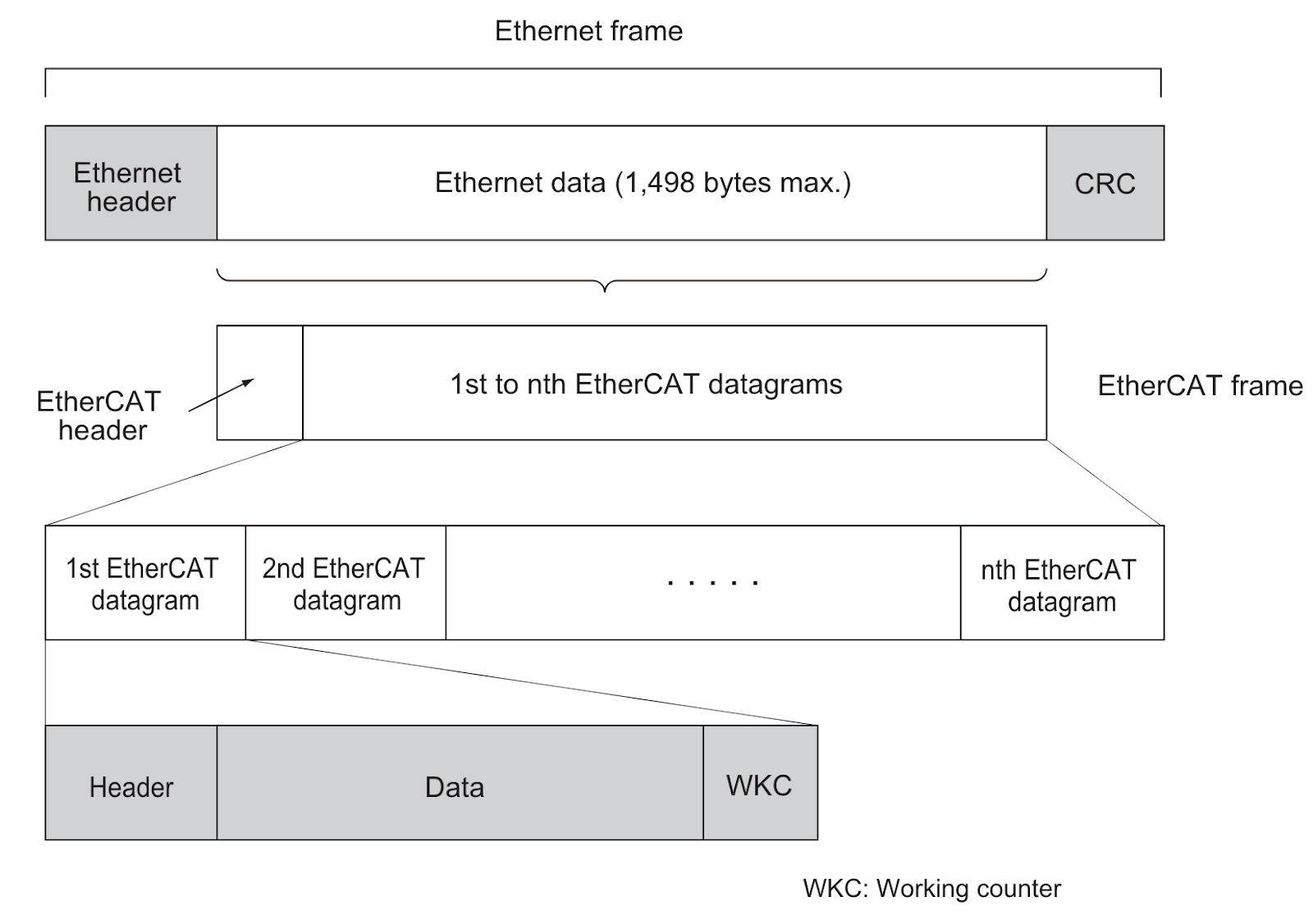
The data exchange, which takes place cyclically between EtherCAT master and EtherCAT slaves, uses EtherCAT datagrams stored directly in the Ethernet frame, each EtherCAT datagram consisting of a Header (containing the data length and one or more slave addresses), a Data, Working Counter (Check-Bit).
It may be easier to imagine that Ethernet frame as a train and the EtherCAT datagram as a train carriage.
Types of EtherCAT Communications
Two types of communication are possible with EtherCAT: PDO and SDO communication.
Process Data Communications (PDO Communications)
PDO communication is a communication method in which data is processed cyclically and in real-time; the EtherCAT master maps the logical process data space to the nodes and implements cyclic communication between the EtherCAT master and slaves.
Mailbox Communications (SDO Communications)
SDO communication is used for message communication. Depending on the needs of the application, the EtherCAT master sends commands to the slaves and the slaves reply to the EtherCAT master.
SDO communication is used to enable the following data communications
- Reading and writing process data
- Slave configuration
- Monitoring slave status
CJ1W-ECT21?
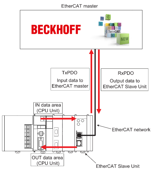
The Cj1W-ECT21 allows data to be exchanged between EtherCAT Master and CPU Units via the EtherCAT network.
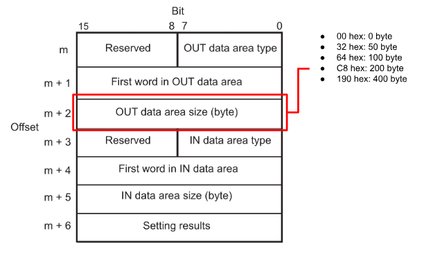
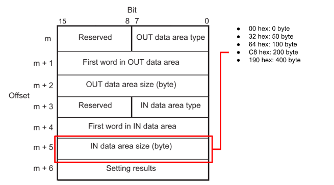
Data Exchange Sizes
The Cj1W-ECT21 allows the user to set the amount of data exchanged on the EtherCAT network from 0, 50, 100, 200 and 400 bytes.
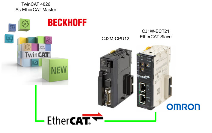
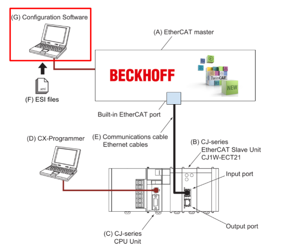
System Configuration
This is an example of an EtherCAT system construction.
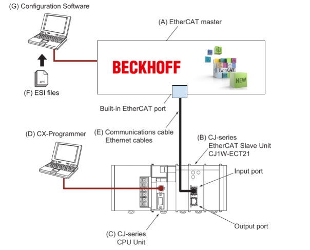
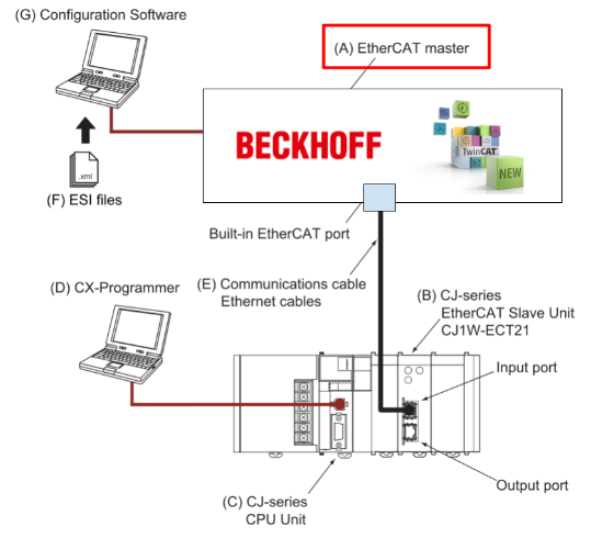
EtherCAT master
The EtherCAT master manages the EtherCAT network, monitors slave status and exchanges I/O data with the slaves.
CJ-series EtherCAT Slave Unit(CJ1W-ECT21)
CJ-series EtherCAT Slave Units on an EtherCAT network.
The following functions are realized.
- Process data communication with the EtherCAT master.
- Message communication with the EtherCAT master (SDO communication).
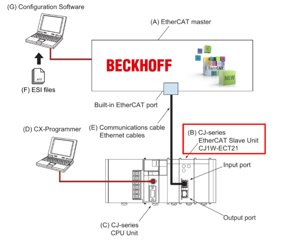
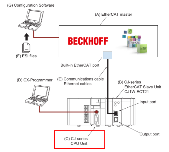
CJ-series CPU
Main unit that controls the CJ-series PLC and updates IO data for other units, slaves, etc.
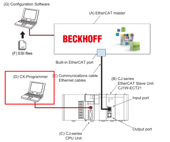
CX-Programmer
The CX-Programmer runs on a PC and is used to set the I/O communication area setting table for communication between CJ-series CPU Units and EtherCAT Slave Units, and to programme, monitor and debug CJ-series PLCs.
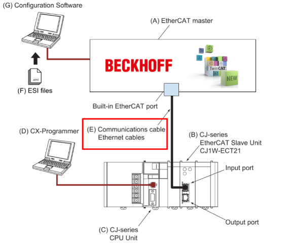
Communications Cable
Use double-shielded cables with aluminium tape and braid of Category 5 (100BASE-TX) or higher, and also use straight wiring.
ESI (EtherCAT Slave Information File)
The ESI File contains EtherCAT slave-specific information in XML format and can be loaded into the EtherCAT master configuration software for easy allocation of slave process data and other settings. The ESI File can also be obtained from the respective EtherCAT slave manufacturer.
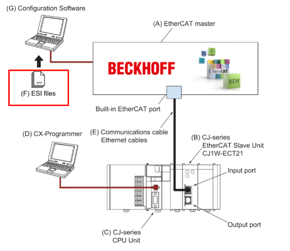
Configuration Software
The configuration software runs on a PC and is used to configure the EtherCAT network and EtherCAT slaves. (In this article, it will be the Beckhoff TwinCAT 4026.)
Layout
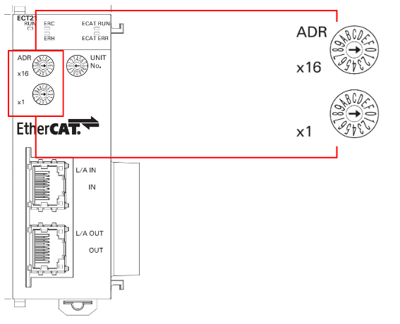
This is an outline drawing of the CJ1W-ECT21.
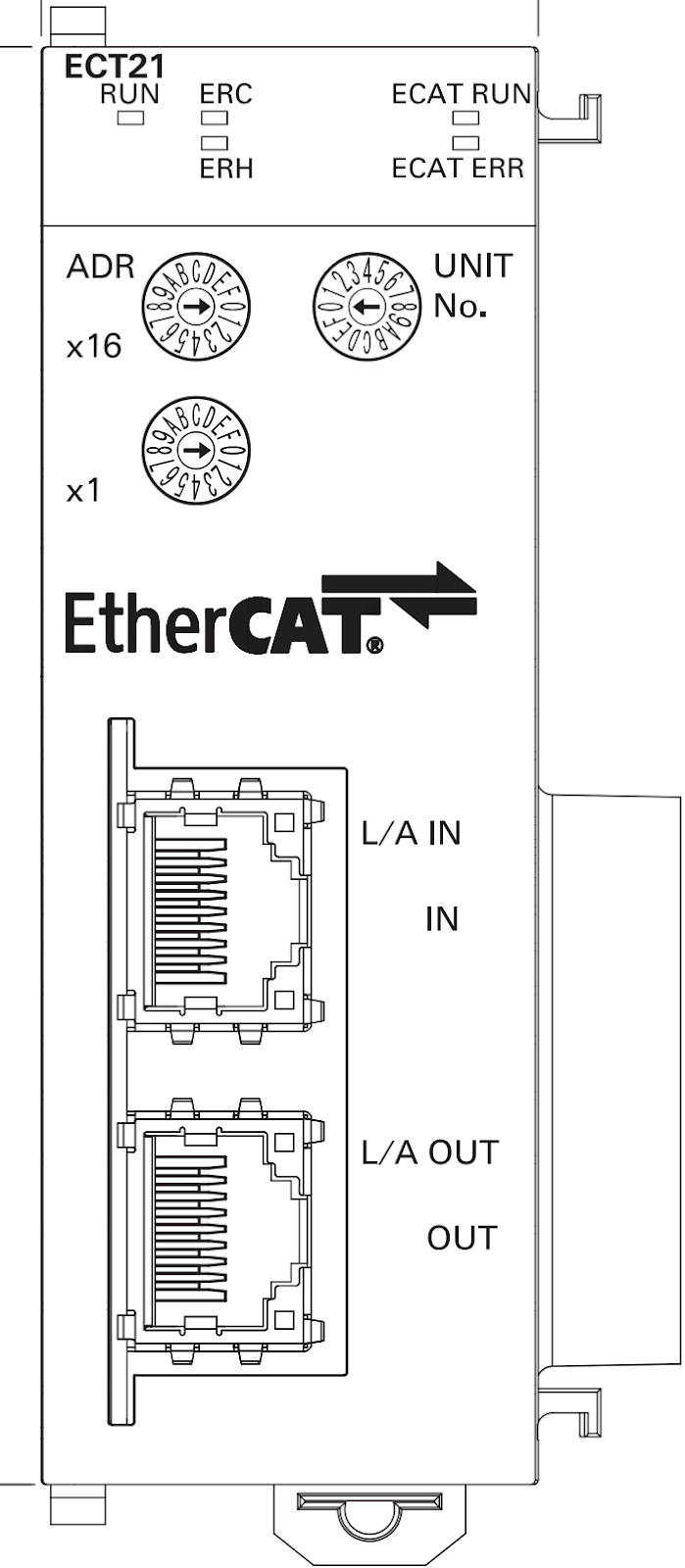
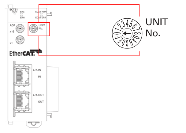
Unit Switch
Unit Switch sets the unit number of the EtherCAT Slave Unit as the CPU Bus Unit. The assignment of data area awards and DM area awards, in which data such as unit status, slave status, I/O communication area setting table and I/O communication area reference table are stored, to a unit is determined by its unit number setting.
And the range that can be set is from 0 to F. The factory setting is 0.
Node Address Switches
Node Address Switches are used to set the node address of an EtherCAT slave unit so that the EtherCAT master can recognise the EtherCAT slave unit.
If 1-255
Use the switch settings to set node addresses from 1 to 255. If these switches are not set to 00, the node address set by the switch is used.
If 0
If the switch is set to 00, set the node address range from 1 to 65535 using the EtherCAT master configuration software.
MAX Units?
Up to 16 EtherCAT slave units can be installed in a CJ-series PLC system if an expansion rack is available.
Memory Allocated
The following CPU unit words are allocated to the EtherCAT Slave Units
- CIO Area words :Contains Module status information.
CIO Area: n = CIO 1,500 + (25 x unit number) - DM Area words: contains I/O communication area setting table T.
DM エリア:m = D30,000 + (100 x unit number)
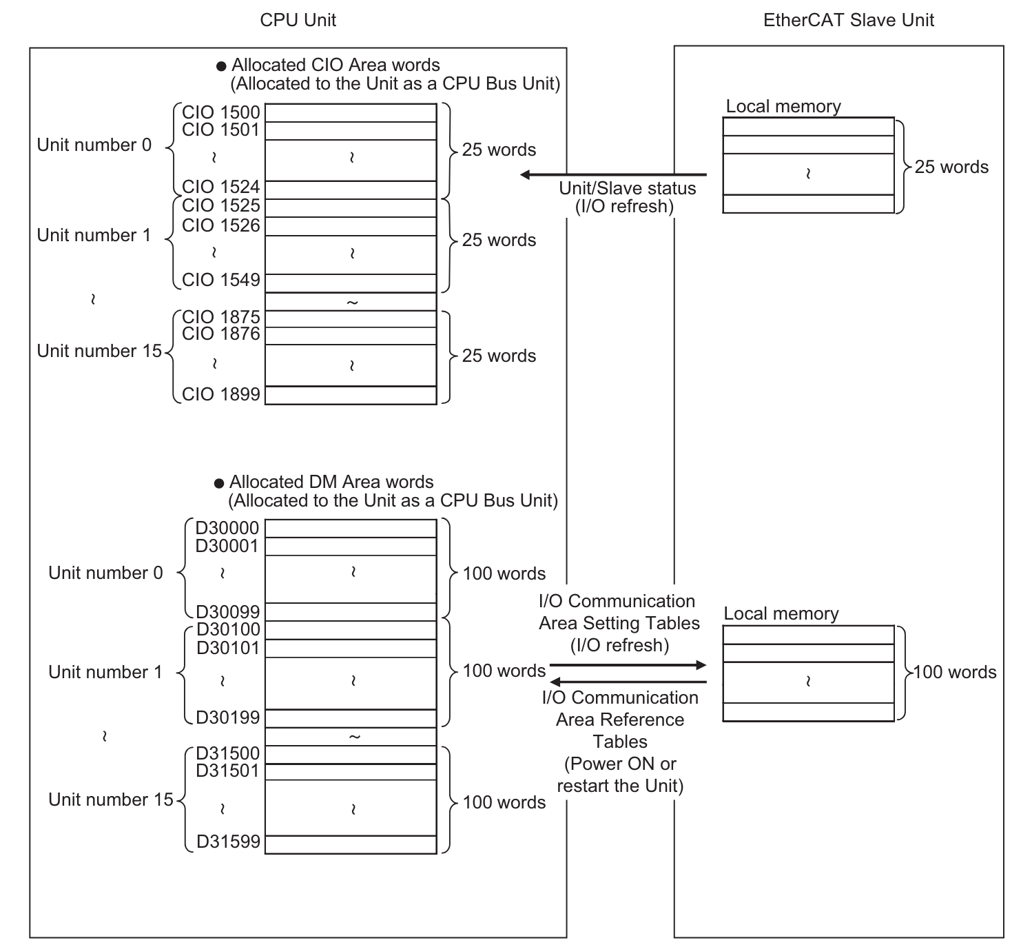
CIO Area Allocations
Start word n = CIO 1500 + (25 x unit number).
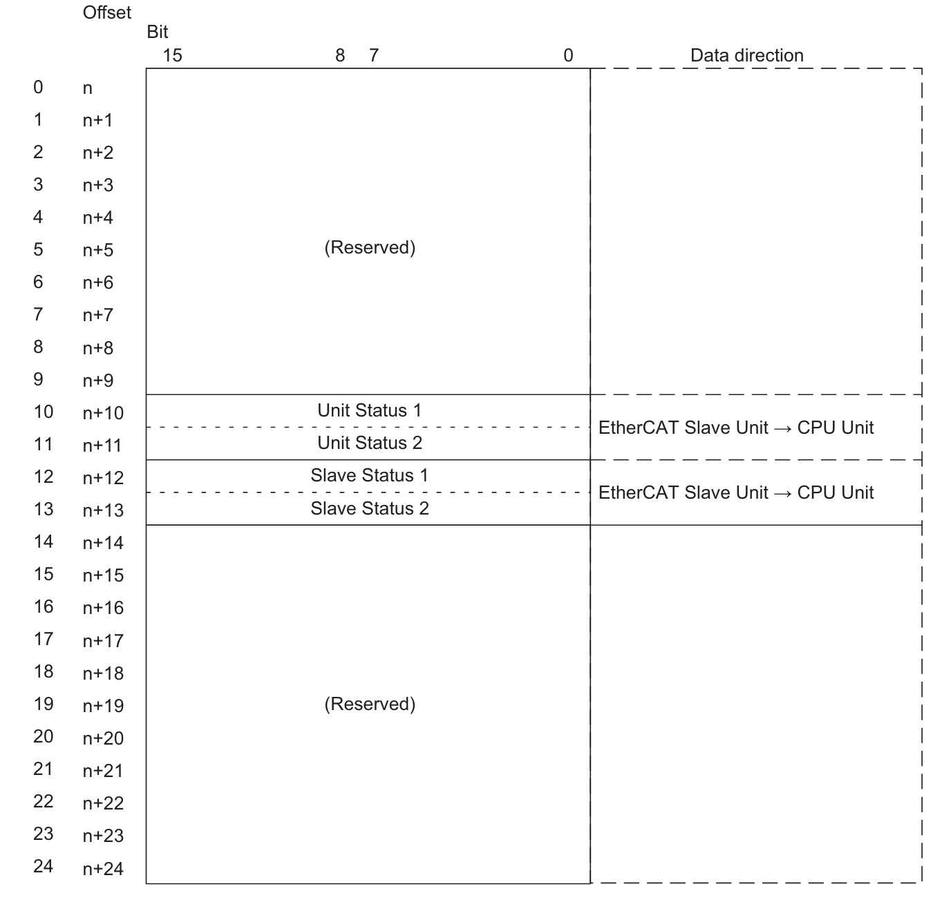
Unit Status 1 (n+10)
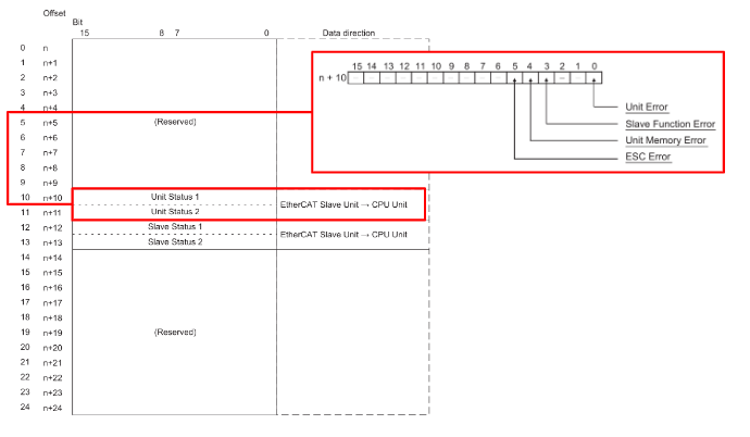
Unit Status 2 (n+11)
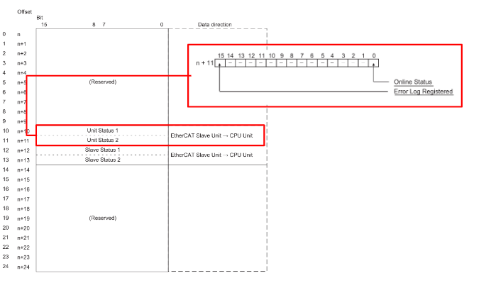
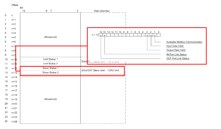
Slave Status 1 (n+12)
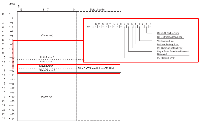
Slave Status 2 (n+13)
DM Area Allocations
Start word m = D30000 + (100 x unit number). It should be noted that the DM area is there to set the I/O words used by the EtherCAT slave unit, but the unit must be restarted for the changes in the I/O communication area configuration table to take effect.
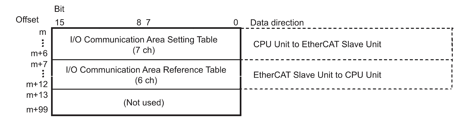
m 00 to 07 OUT data area
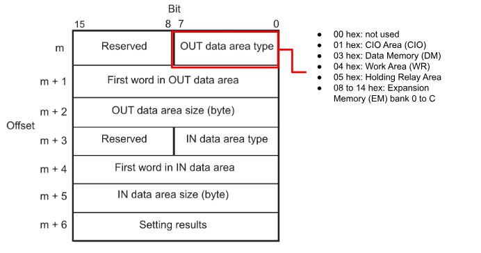
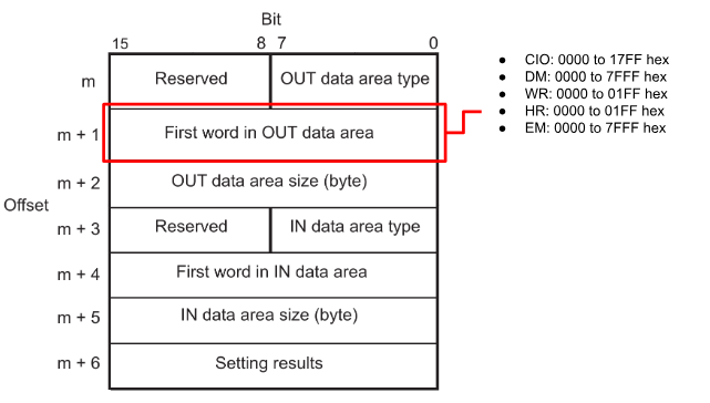
m + 1 00 to 15 First word in OUT
m + 2 00 to 15 OUT data area Size
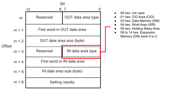
m + 3 00 to 07 IN data area
m + 4 00 to 15 First word in IN
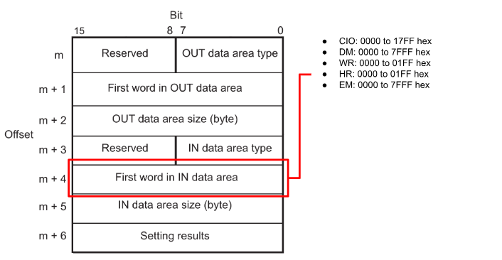
m + 5 00 to 15 IN data area size
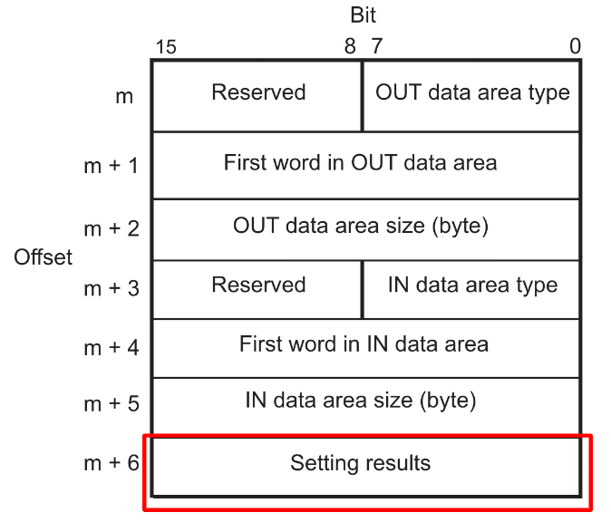
Status Code
This is the result of the settings. Please refer to the instruction manual for details.
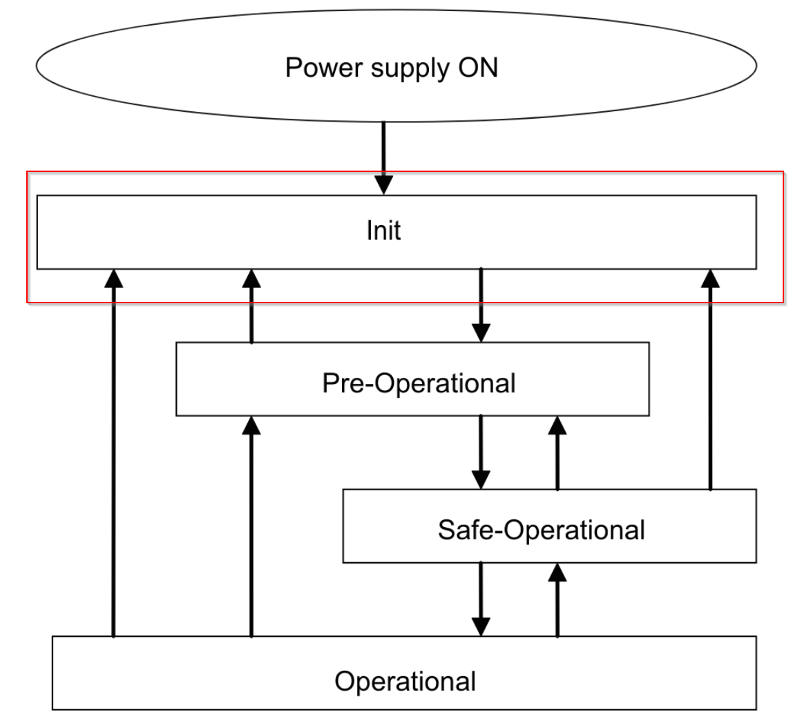
State transition
The state transition model of the communication control of an EtherCAT slave unit is controlled by the EtherCAT master. The following diagram shows the transition of the communication state from power on.
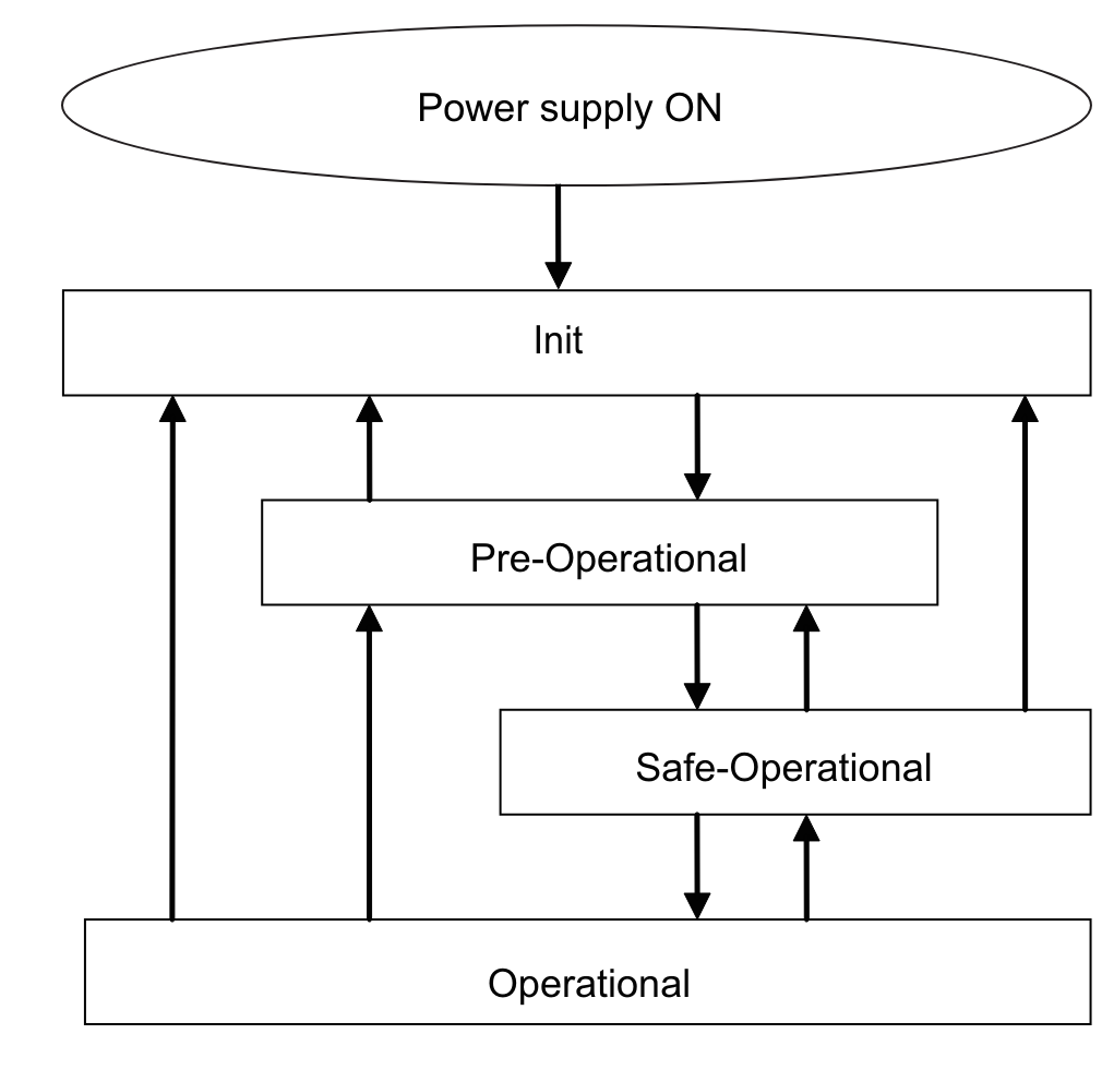
Init
Communication is being initialized and in this state the EtherCAT Master and EtherCAT Slave cannot communicate.
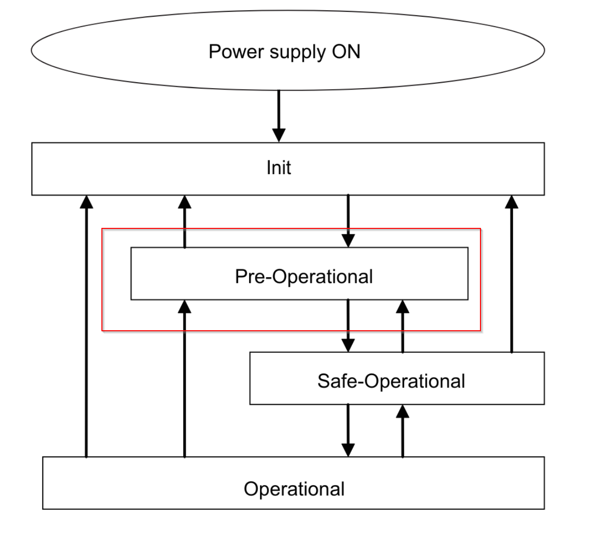
Pre-Operational
In this state, only SDO communication (message communication) is possible and this state is entered when Init is completed. Initialise the network settings in this state.
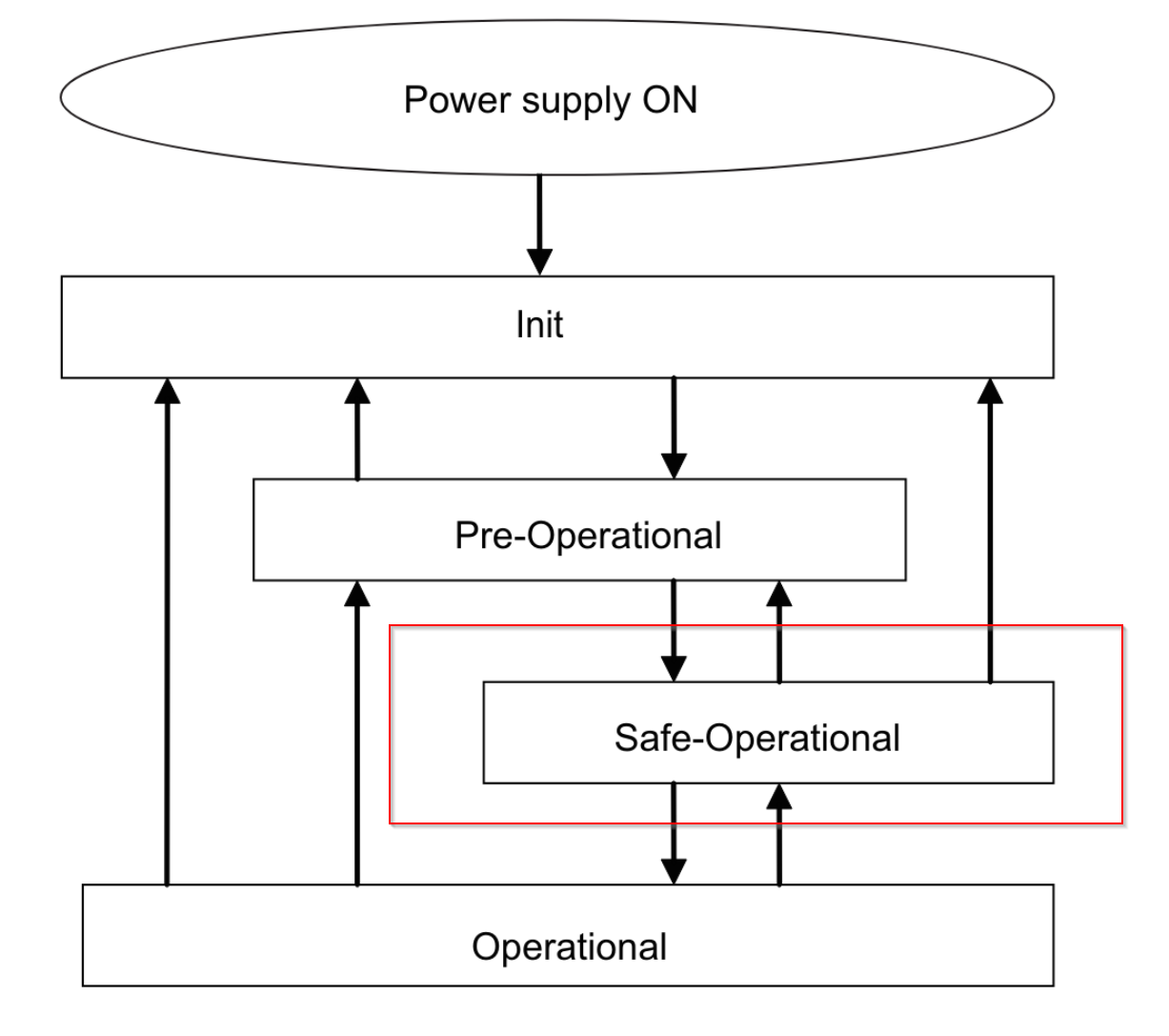
Safe-Operational
In this state, both SDO communication (message communication) and PDO transmission are possible. Status and other information is sent by the EtherCAT Slave Unit.
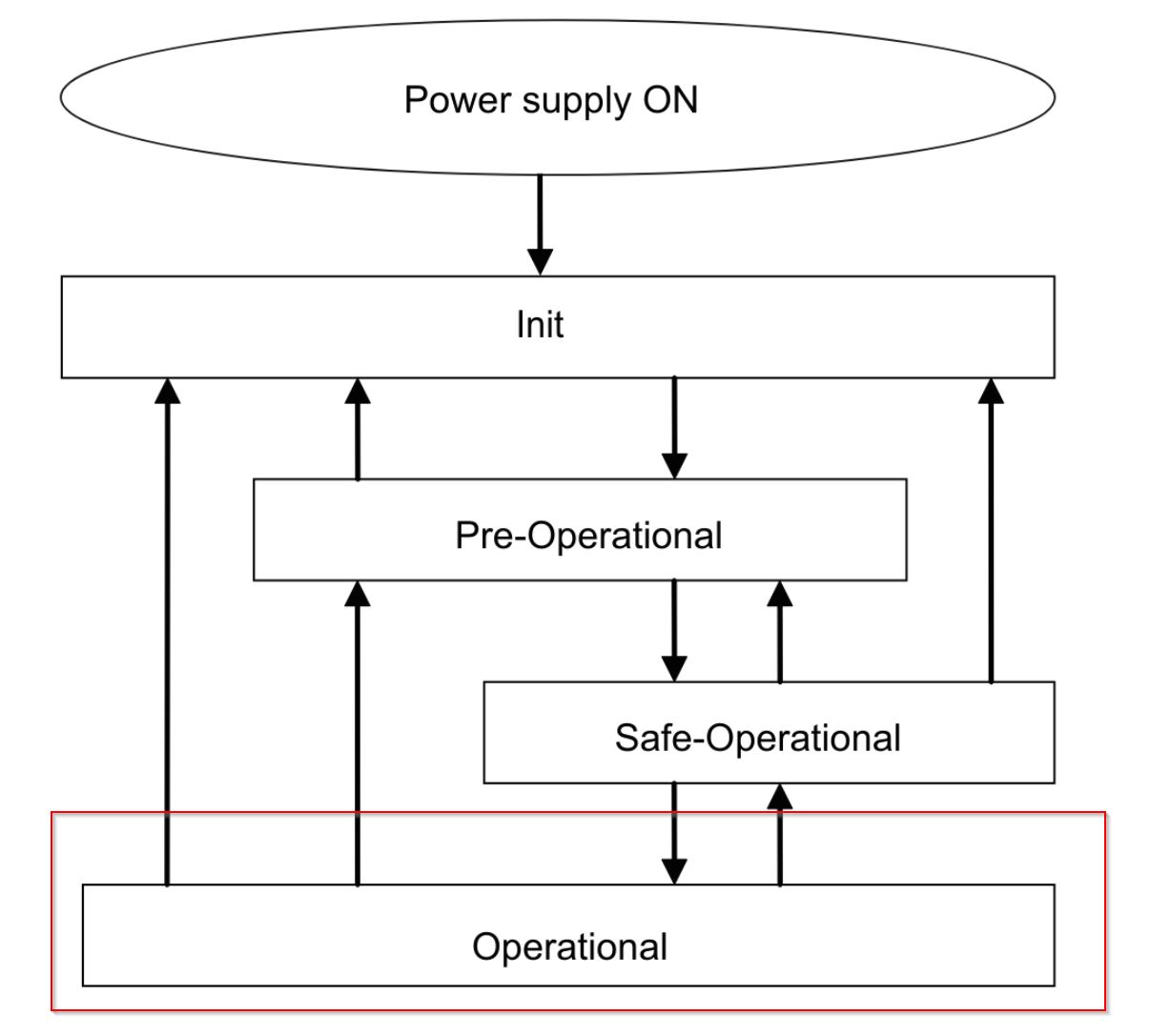
Operational
This is the normal state of communication. PDO communication is used to control I/O data.
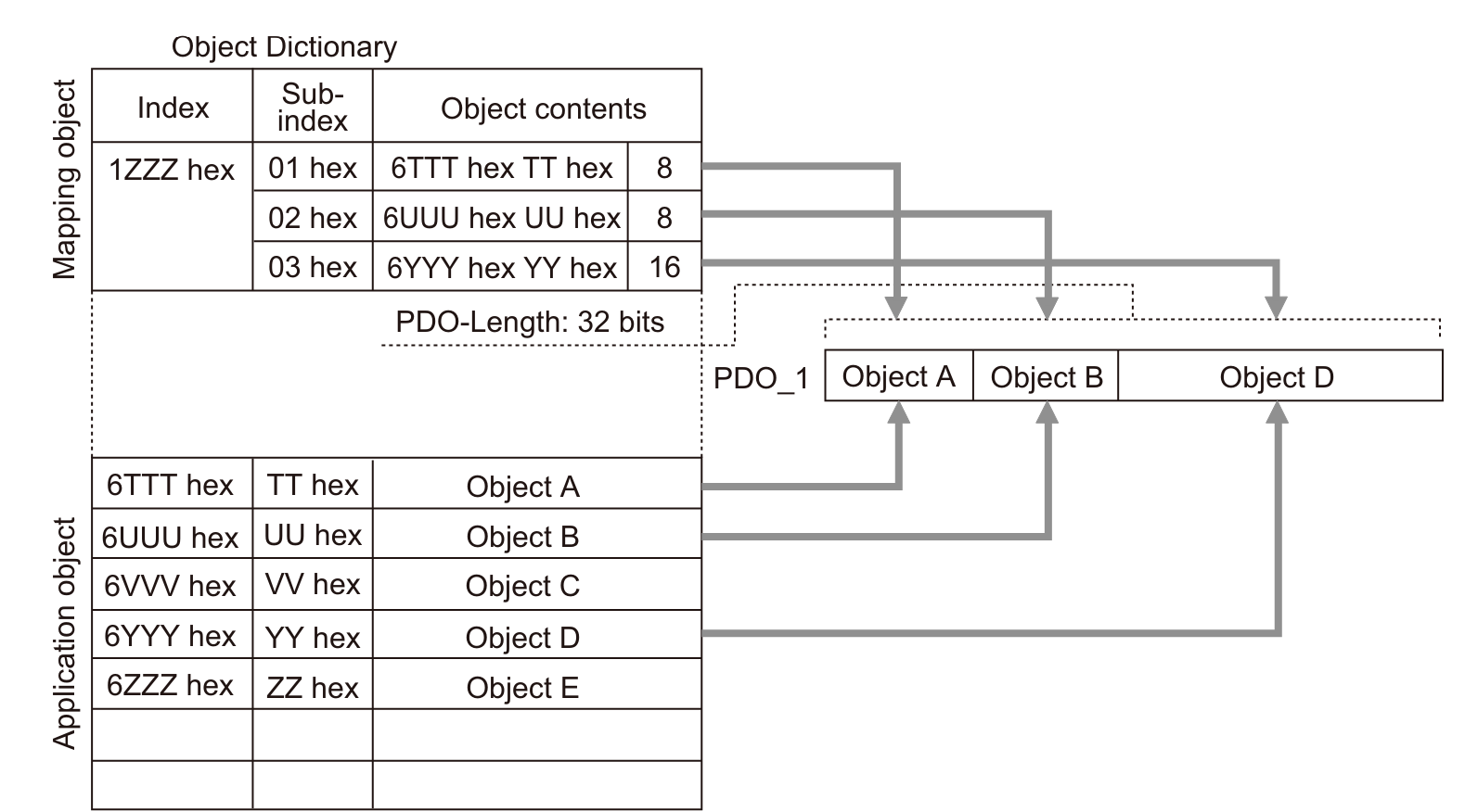
PDO Mappings
The PDO mapping object contains the I/O data of the EtherCAT slave unit.
- RxPDO PDO mapping objects are managed in the Object Dictionary at indexes 1600 to 17FF.
- TxPDO PDO mapping objects are managed by index 1A00 to 1BFF in the Object Dictionary.
RxPDO

TxPDO
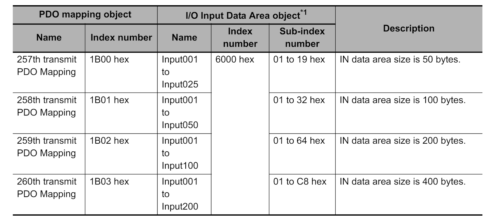
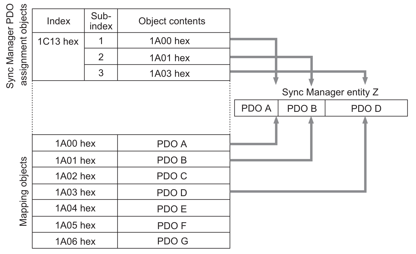
In addition, several PDOs can be assigned to an EtherCAT slave.
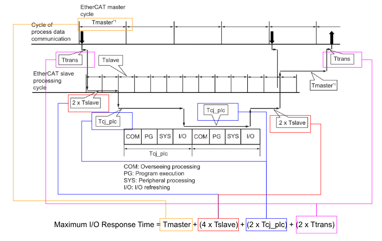
Communications Performance
The I/O response time of an EtherCAT Slave Unit is the time between when the CJ-series CPU Unit processes output data from the EtherCAT master and when the EtherCAT master inputs the processing results.
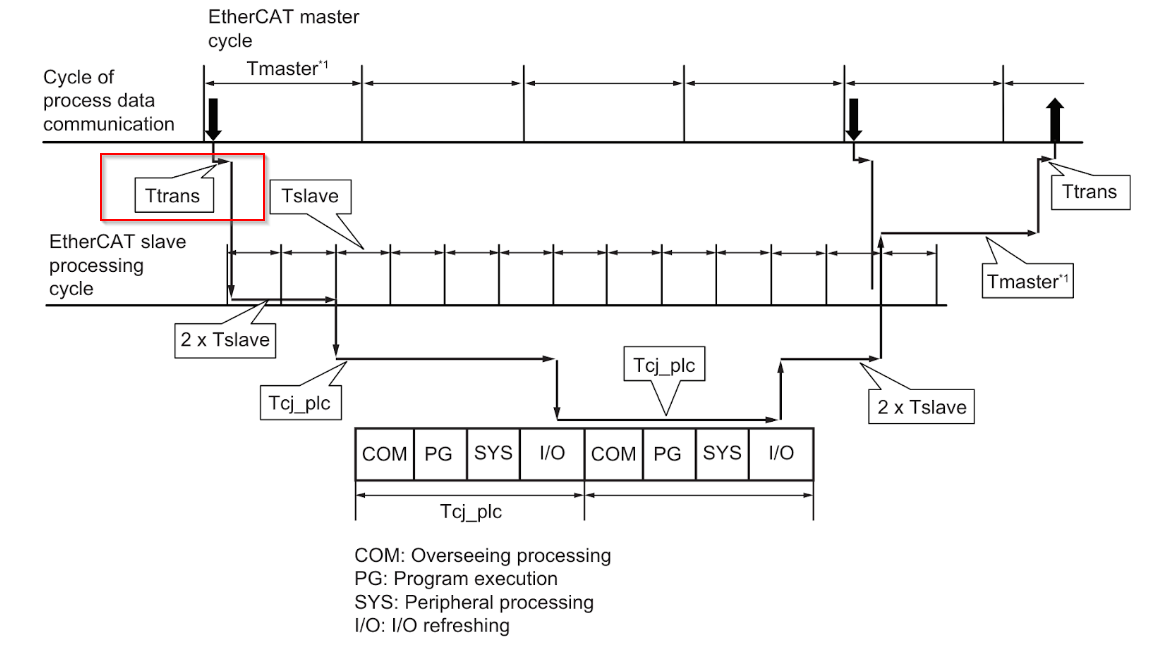
The timing chart for I/O response times is shown in the diagram below.
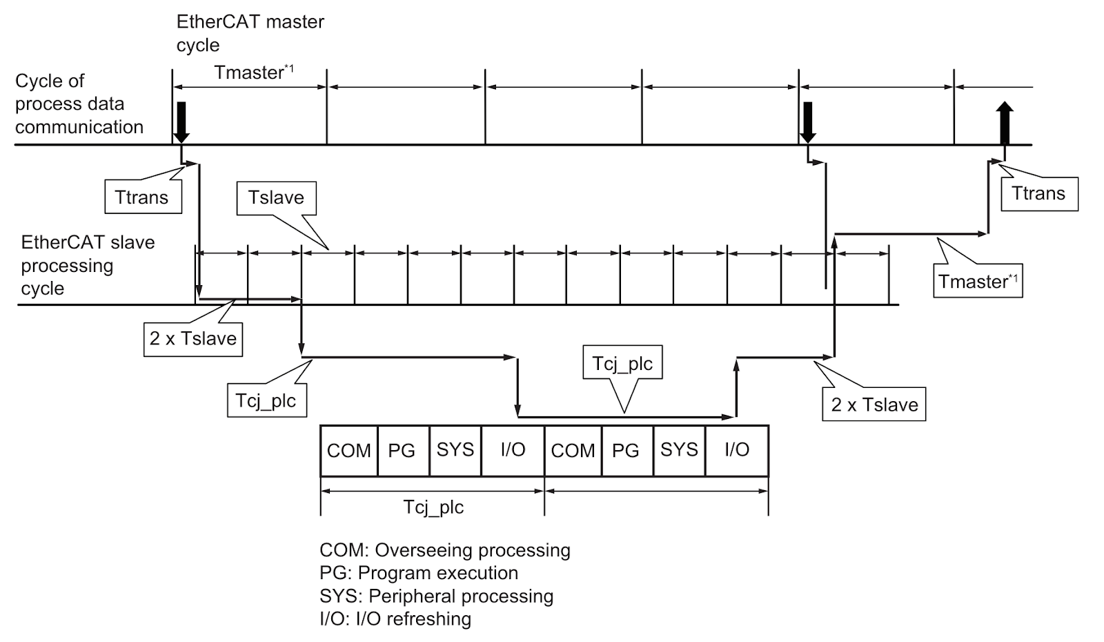
Tmaster
The cycle time of the EtherCAT Master assumes that the cycles of the EtherCAT Master are the same as those of the process data communication. For more information, please refer to the instruction manual of the EtherCAT Master used in your application.
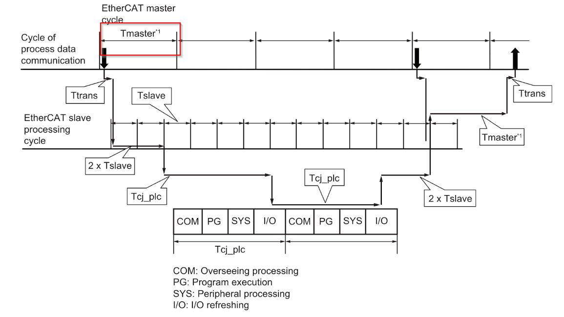
Tslave
This corresponds to the processing time of the EtherCAT slave unit.
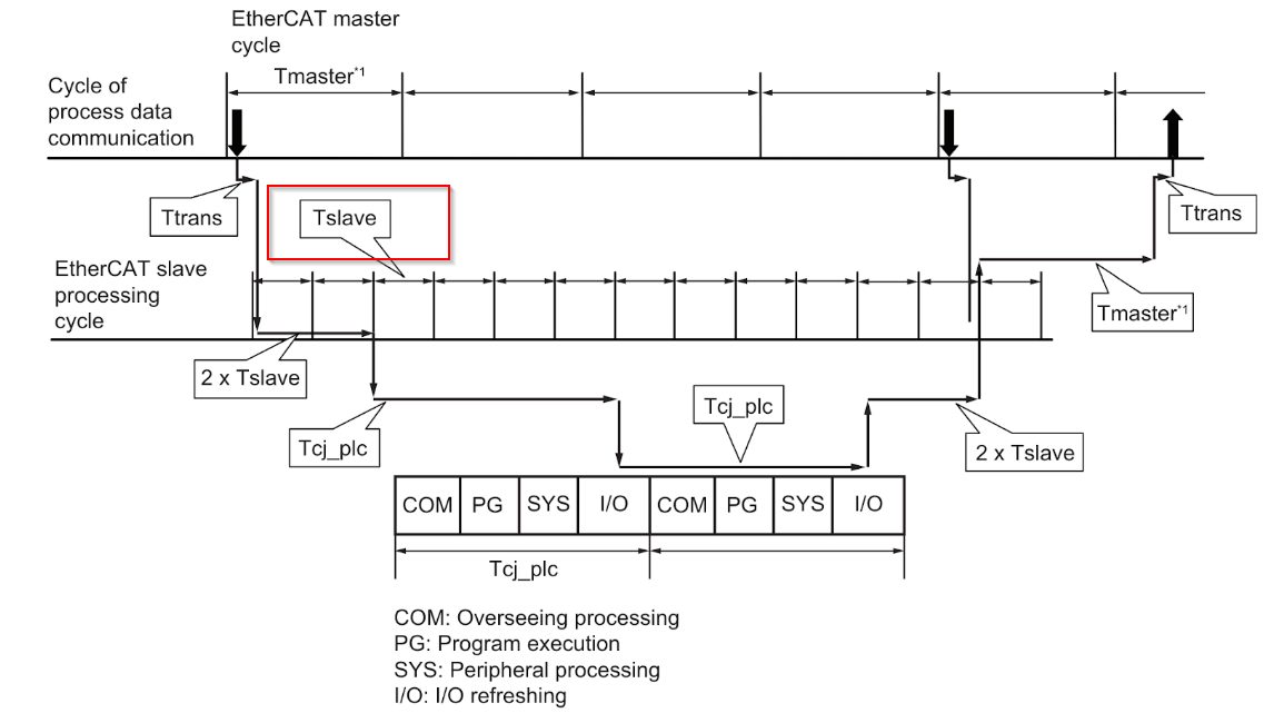
Tcj_plc
This corresponds to the cycle time of CJ-series CPU units.
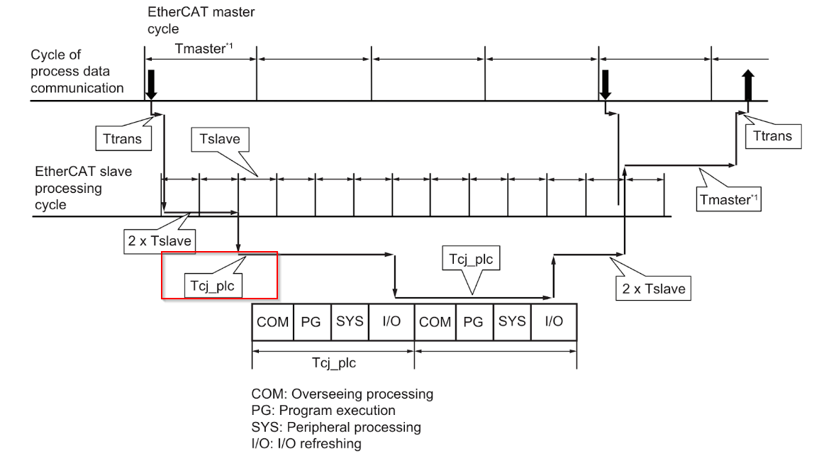
Ttrans
This corresponds to the transmission time of the EtherCAT master.
formula
The formula for calculating I/O response time is shown below.
Maximum I/O Response Time = Tmaster + (4 x Tslave) + (2 x Tcj_plc) + (2 x Ttrans)
Implementation
OMRON Side
Let’s build from CJ2B-ECT21.
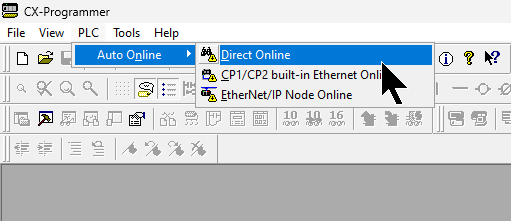
Read Configuration
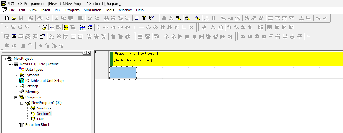
Start CX-Programmer and click PLC>Auto Online>Direct Online.
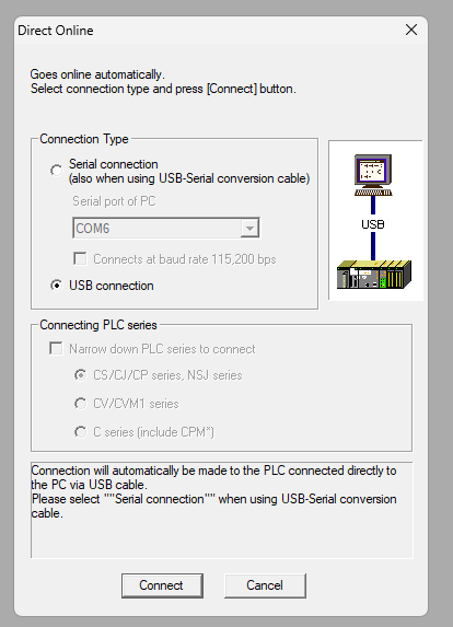
I am connected via USB, so I select USB Connection and proceed with Connect.
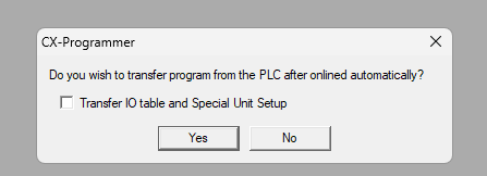
Proceed with Yes.
Done!The project and Hardware Configuration have been uploaded.
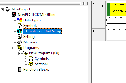
IO Table
Next, click on IO Table and Unit Setup to change the Hardware Configuration.
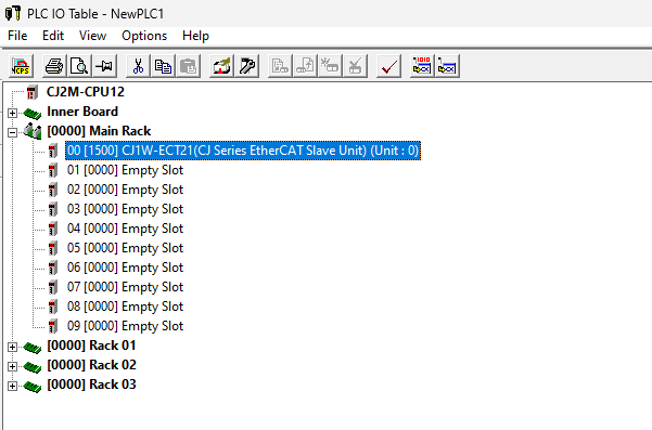
The PLC IO Table screen will appear and open the CJ1W-ECT21 used in this article.
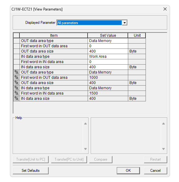
Configuration
This is the CJ1W-ECT21 settings screen.
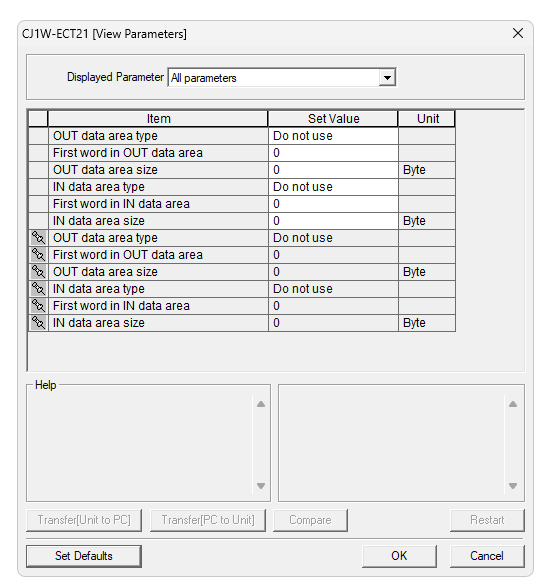
This is the setting for this time.
- Out Data area Type is Data Memory (D) and the first address is set to D0, 400 Byte.
- In Data area Type is Work Area (W) and the first address is set to W0, 400 Byte.
Transfer[PC to Unit]
Transfer the settings to the CJ1W-ECT21 using Transfer [PC to Unit].

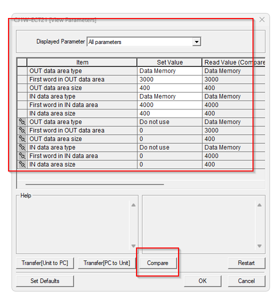
Compare
The Compare function can also be used to match Offline and Online settings.
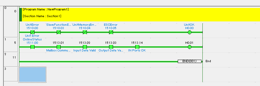
Program
This is a simple program that acquires the communication status between the CJ1W-ECT21 and the EtherCAT Master (in this case Beckhoff) or the status of the module itself.

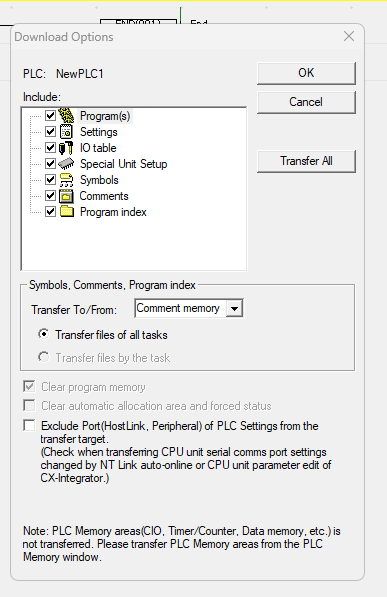
Download
Download your project to the CPU.

Click Transfer All and OK to transfer all data to the CPU.
Proceed with Yes.
Proceed with Yes.
Please wait a moment…
Done!
Switch the Omron CJ CPU to Run Mode with Yes.
Beckhoff Side
The next step is to build the Beckhoff side.
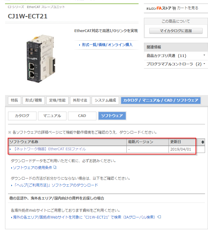
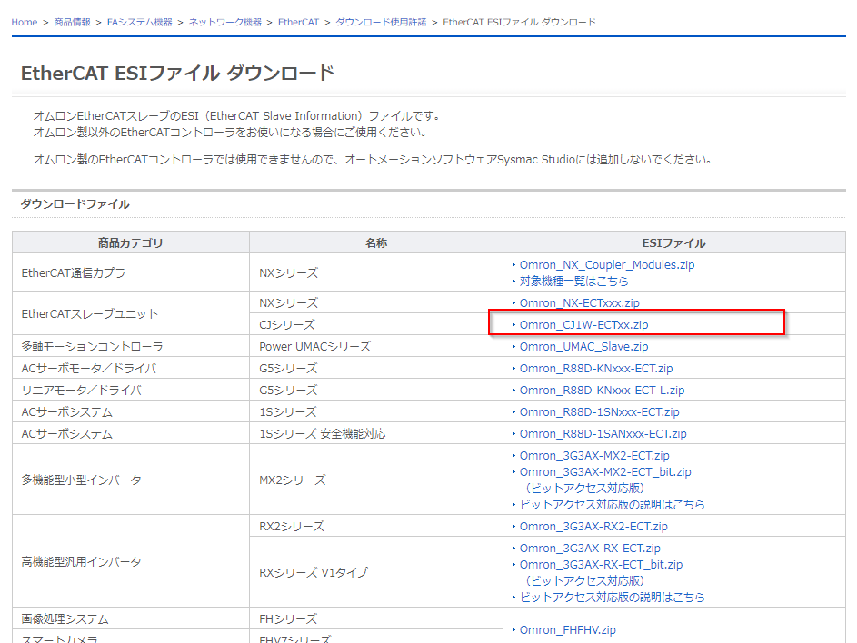
Download ESI File
Download the ESI File from the Omron website.
https://www.fa.omron.co.jp/products/family/3439/download/software.html
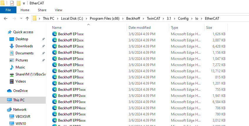
Install ESI File
ESI File is stored in Program Files(x86)/Beckhoff/TwinCAT/3.1/Config/io/EtherCAT.
The storage location of the ESI File and other files has changed since 4026.
New Project
To create a new project on the TwinCAT 4026, click on File>New>Project.
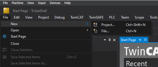
Select TwinCAT XAE Project (XML Format) and proceed with >Ok.
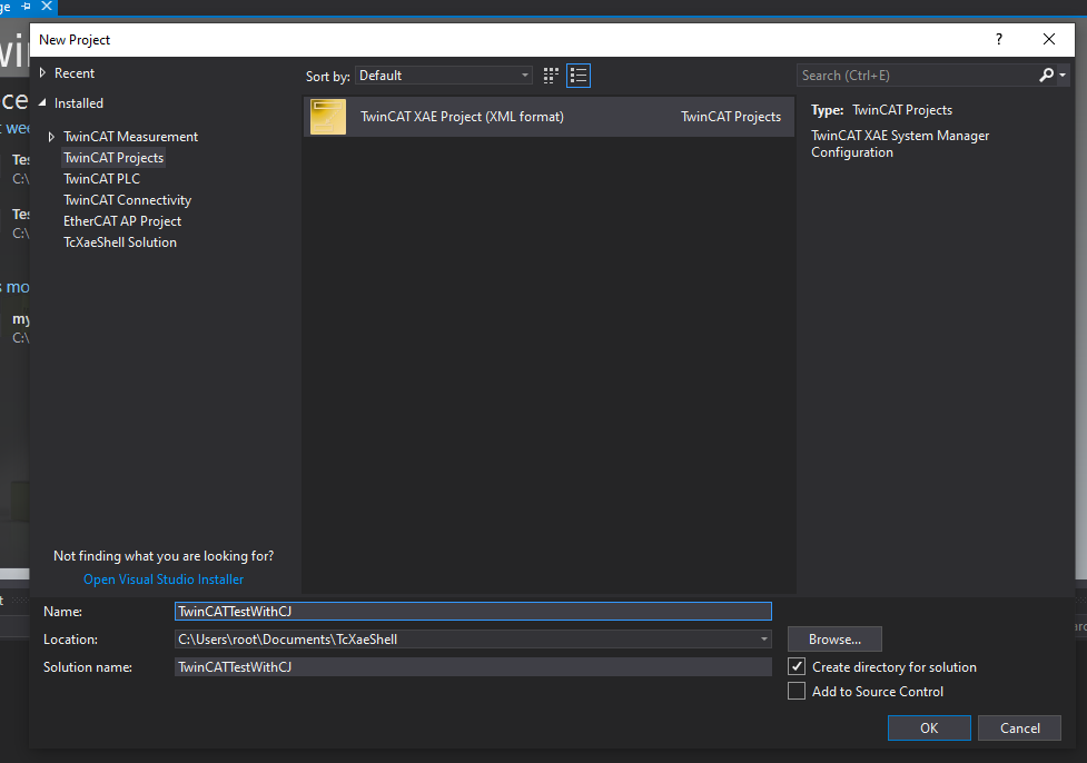
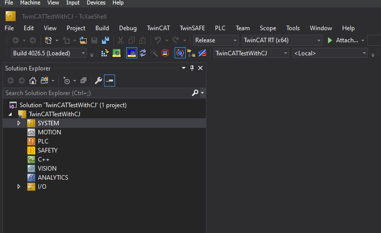
Done!New projects have been added.
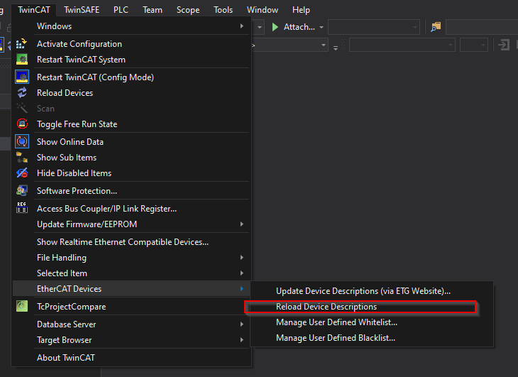
Reload ESI File
Reload the ESI File in TwinCAT>EtherCAT Devices>Reload Device Descriptions.
Add EtherCAT Master
To add an EtherCAT Master, go to Devices>Add New Item.
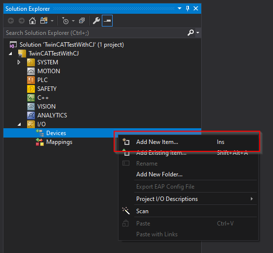
Add EtherCAT Master.
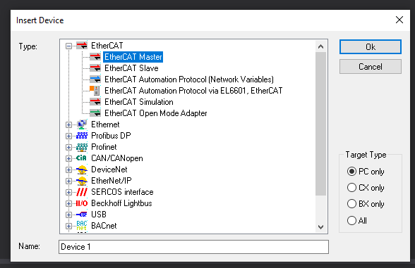
Configure the Ethernet Interface to be used as EtherCAT Master.
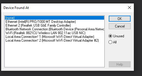
Done!EtherCAT Master has been added.

Scan Network
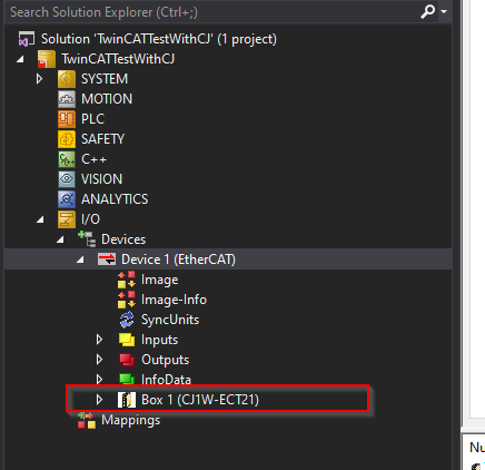
Next, use TwinCAT’s Scan network to search for CJ1W-ECT21.
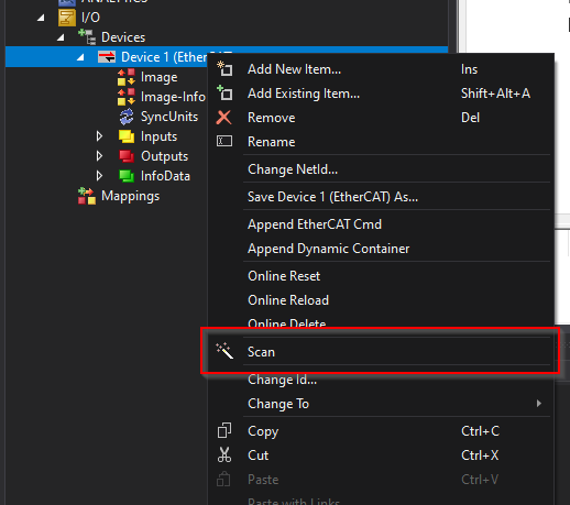
Done!CJ1W-ECT21 was found.
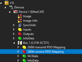
Configrure Slots
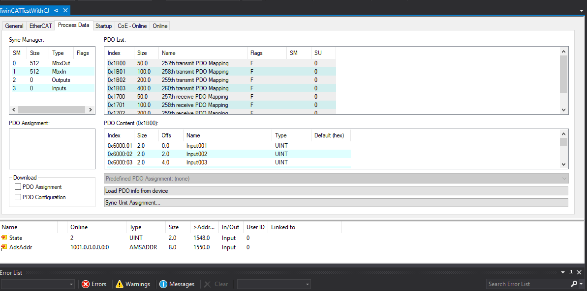
Double-click CJ1W-ECT21, open the Process Data tab and set up PDO Mapping.
Outputs
The CJ1W-ECT21 has just been set up with 400 Bytes of output data, so put a Check Box of 0x1703.
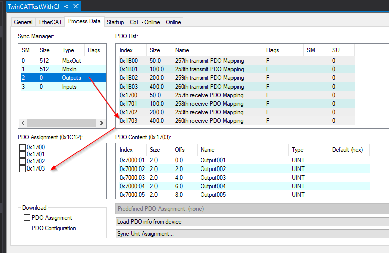
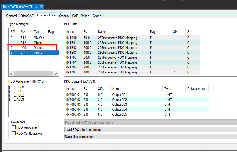
A 400 Bytes PDO has been added to the Outputs Slot.
Inputs
The CJ1W-ECT21 has just been set up with 400 Bytes of input data, so a Check Box of 0x1B03 is inserted.
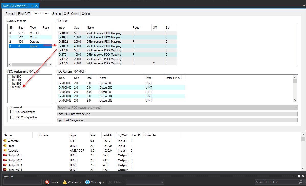
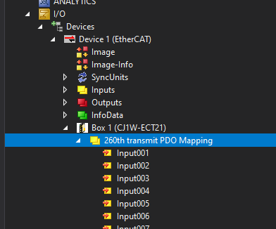
A 400 Bytes PDO has been added to the Inputs Slot.
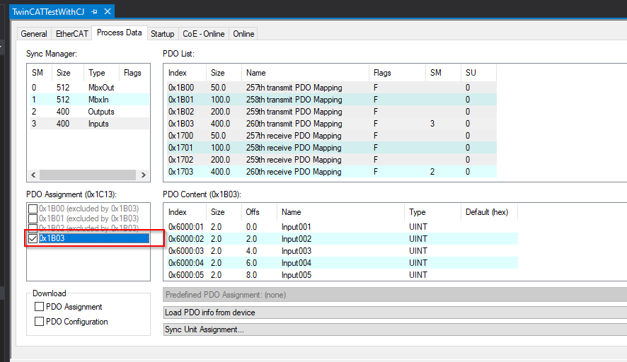
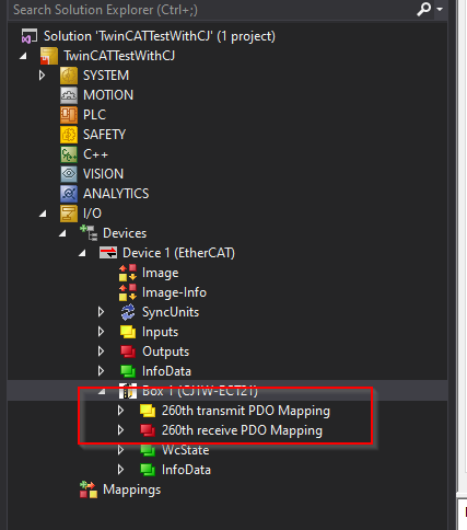
Result
PDO Mapping of inputs and outputs has been added.
Add PLC
Add a PLC: right-click on PLC>Add New Item.

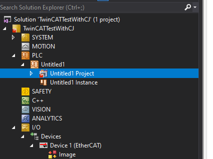
Select Standard PLC Project and add it with >Add.
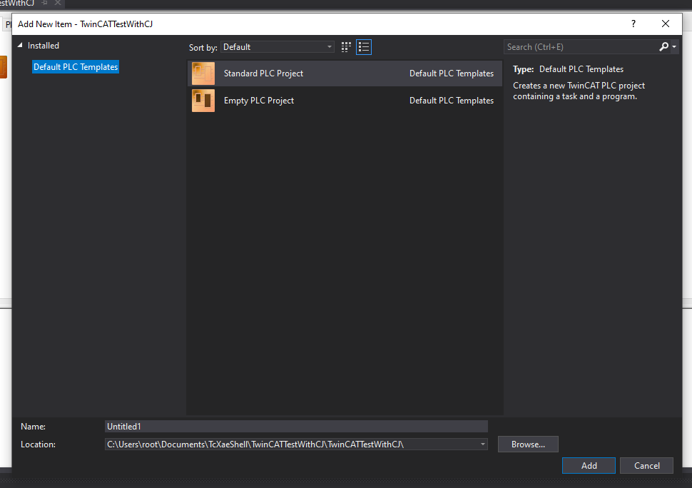
Done!PLC projects have been added.
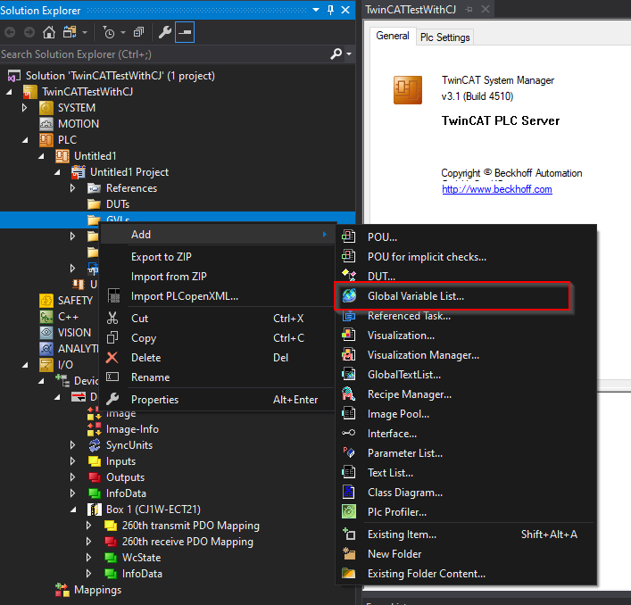
Add GVL
To add a GVL, add GVLs>Right click>Global Variable List.
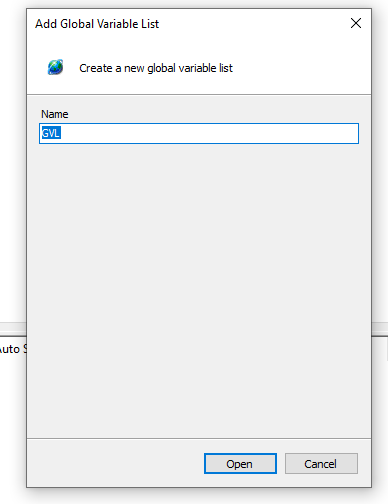
Enter the GVL name.
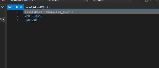
Done!
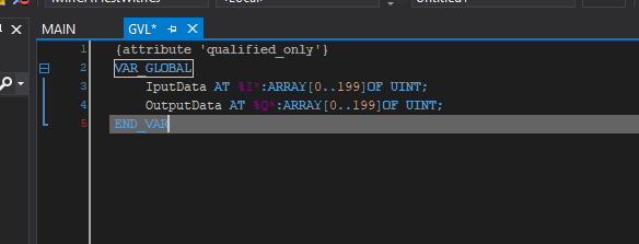
Define process input/output data.
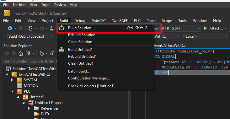
Build
Compile the project under Build>Build Solution.
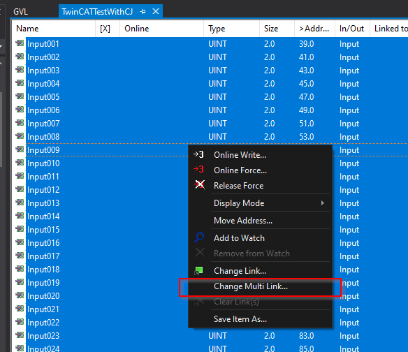
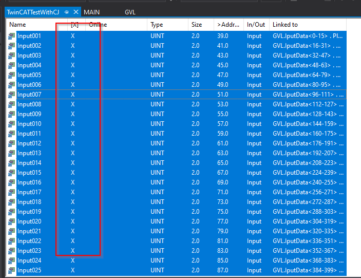
Map Input
Mapping with CJ1W-ECT21 input PDOs and projects.
Select all process input data > right-click > Change Mulit Link.
Link with the GVL.InputData defined earlier.
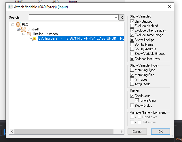
Done!The process input data mapped to the project is marked with an “X”.
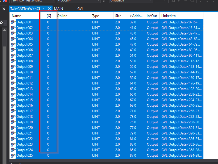
Map Output
Mapping CJ1W-ECT21 output PDOs and projects.
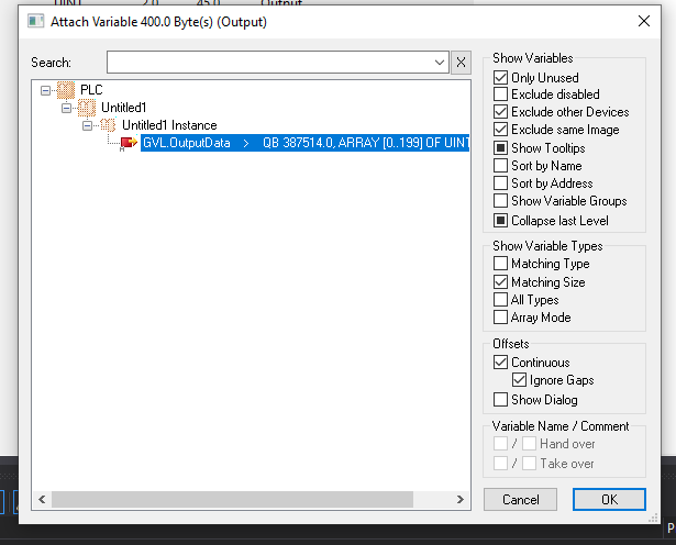
Select all process output data > right-click > Change Mulit Link.
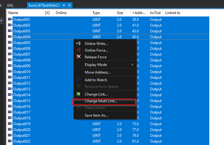
Link with the GVL.OutputData defined earlier.
Done! The process output data mapped to the project is marked with an “X”.
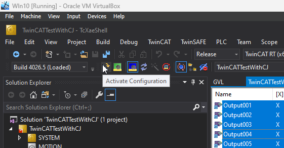
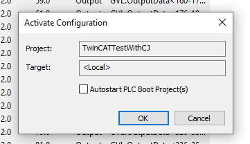
Activate Configuration
Download the Hardware Configuration to Runtime with Activate Configuration.
Proceed with Ok.
If no licence, proceed to licence entry with Yes.
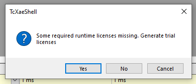
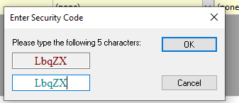
Enter licence.
Switch Runtme to Run mode with Ok.
Login
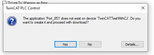
Click Login to download the User programme.

Proceed with Yes.
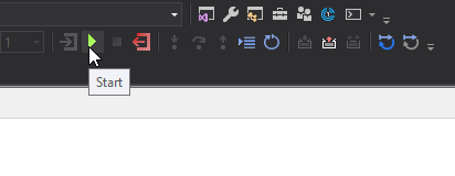
Start to start the programme with Start.
Result
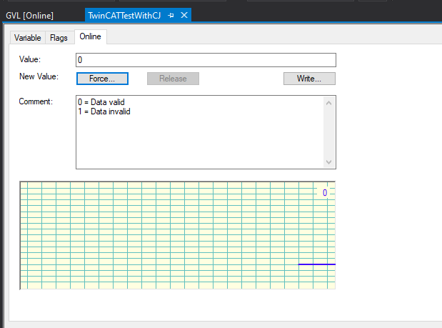
Check the communication status from the WcState variable in CJ1W-ECT21.
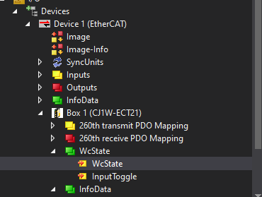
Currently 0 and the PDO data communicated and exchanged with the CJ1W-ECT21 is valid.
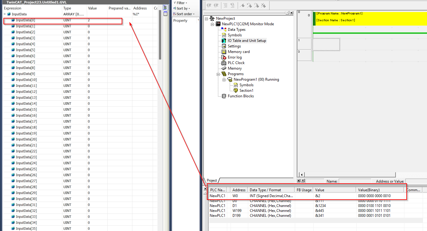
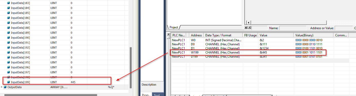
The data output from TwinCAT could be received by the CJ1W-ECT21.
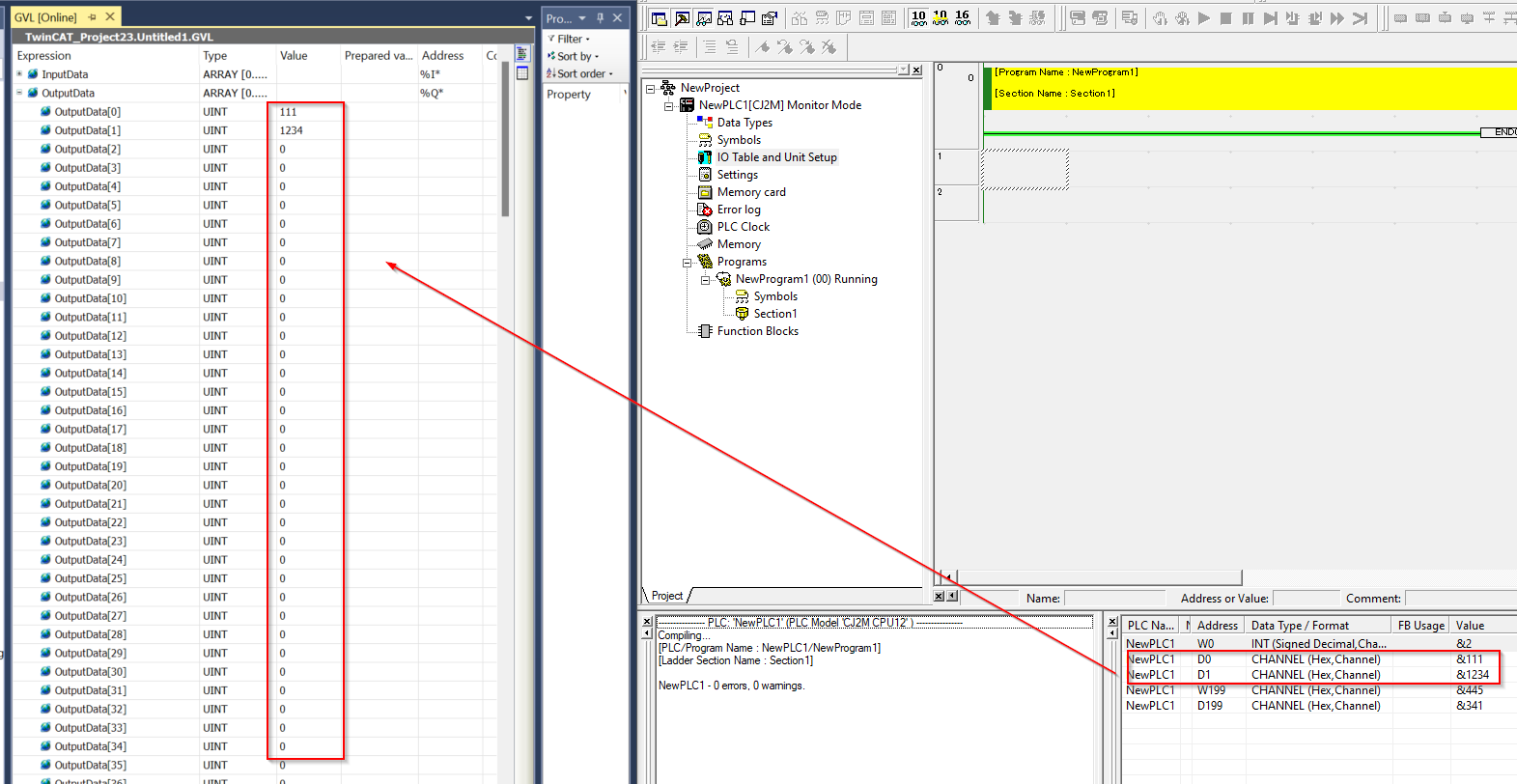
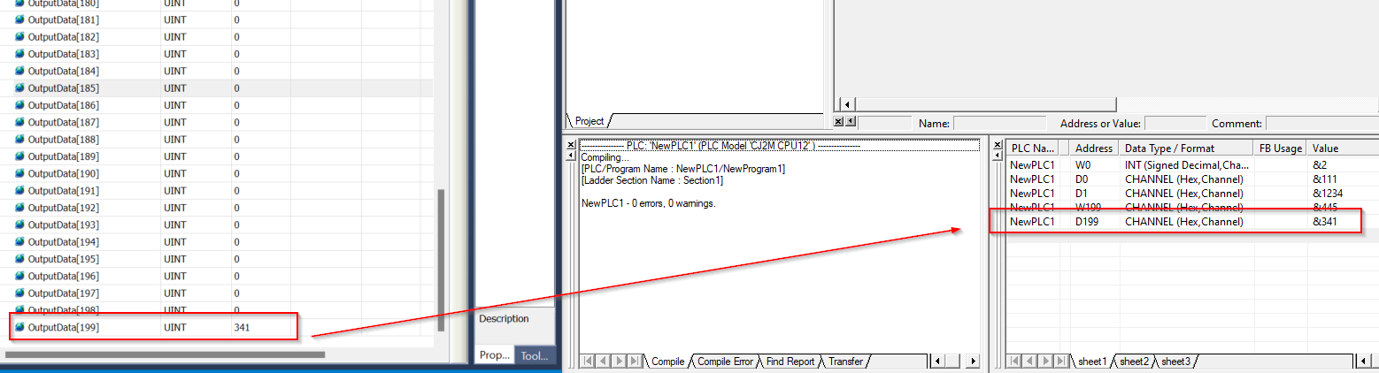
The data output from the CJ1W-ECT21 could be received by TwinCAT.
The current module status can also be checked from the CJ1W-ECT21 ladder.