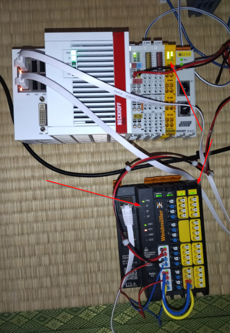
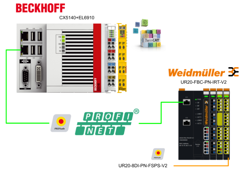
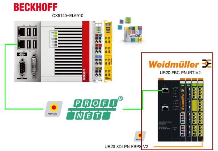
This article uses Beckhoff’s TwinSAFE Logic Terminal EL6910 to set up Profisafe Master and connect it to Weidmuller’s Profisafe Slave. The EL6910 is not only for FSoE!
Let’s enjoy FA.
PROFIsafe With EL6910
When implementing PROFIsafe communication in a TwinCAT application, the following points should be noted. There are also restrictions on the transmission of PROFIsafe within EtherCAT.
- PROFIsafe Telegram only via E-bus and PROFINET/PROFIBUS
According to the PROFIsafe policy, PROFIsafe can only be used via PROFIBUS and PROFINET fieldbuses or backplane buses (e.g. E-bus).
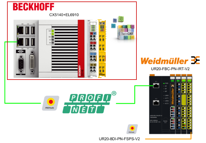
Valid PROFIsafe configurations
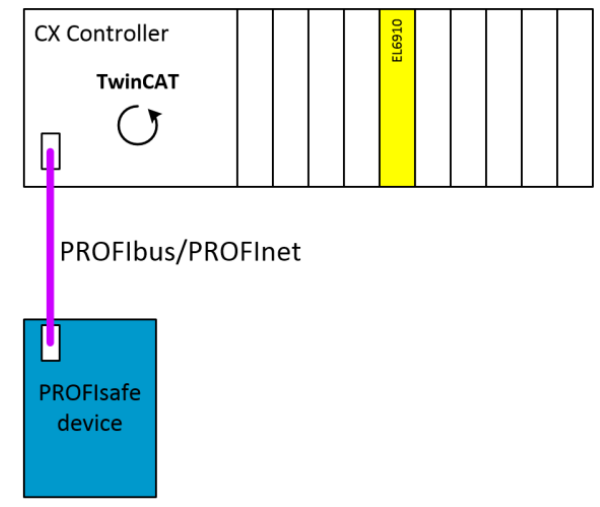
This configuration applies to PROFIsafe master and PROFIsafe slave configurations, e.g. when only EtherCAT terminals are connected to the CX controller and data exchange is only possible via PROFInet/PROFIbus. PROFIsafe can be used when only the EtherCAT terminal is connected to the CX controller and data exchange is only possible via PROFInet/PROFIbus.
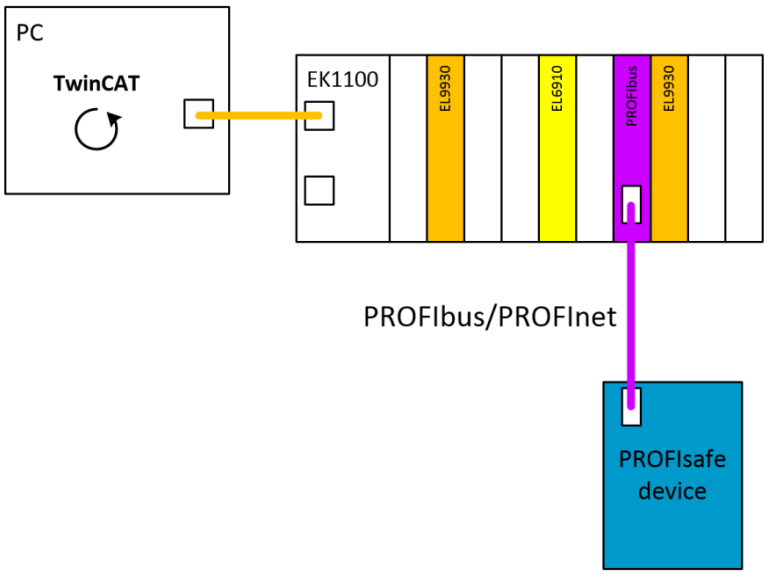
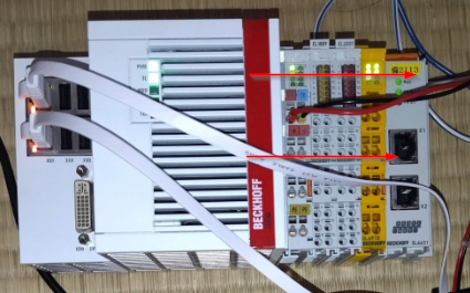
If, for example, a TwinCAT PC is used for data exchange with an EtherCAT terminal via EtherCAT, the PROFIsafe telegram must not go outside the EK1100 station. For this reason, the EL6910 is connected to the EK1100 station together with the EL6631/EL6731 PROFIbus master. The following configurations are therefore valid.
UR20-FBC-PN-IRT-V2?
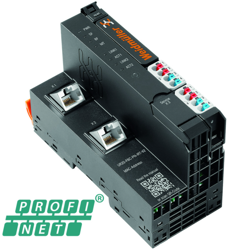
The UR20-FBC-PN-IRT or UR20-FBC-PN-IRT-V2 fieldbus coupler is a PROFINET I/O participant certified by the PROFINET user organization. The coupler is the head module of the u-remote system bus and can connect up to 64 active u-remote modules.
The PROFINET coupler has two Ethernet ports and the integrated switch supports line network structures. The coupler can be accessed by system-independent web server applications via the USB service interface or Ethernet.
Thus, all information such as diagnostics, status values and parameters can be read and all connected modules can be simulated or enforced.
The station’s mains power supply is built into the coupler. Power is supplied from two 4-pole connectors and is divided into input and output current paths.
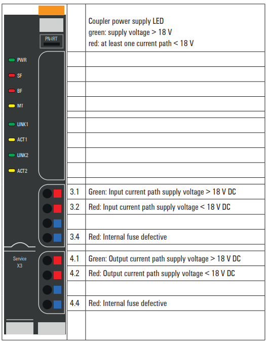
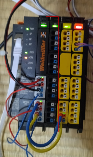
Layout
This is a Layout of the UR20-FBC-PN-IRT-V2.
UR20-8DI-PN-FSPS-V2?
The UR20-8DI-PN-FSPS or UR20-8DI-PN-FSPS-V2 digital input module is a safety I/O module for the PROFIsafe protocol。
The module can detect up to eight binary control signals; 2-wire, 3-wire or 4-wire connections allow two sensors to be connected to each connector.
If the supply current of 0.8 A per plug is not sufficient, the auxiliary output of another module in the same power segment (e.g. potential distribution module) must be used to realize the sensor supply.
Status LEDs are assigned to each channel. The module electronics supply power to the connected sensors from the input current path (IIN).
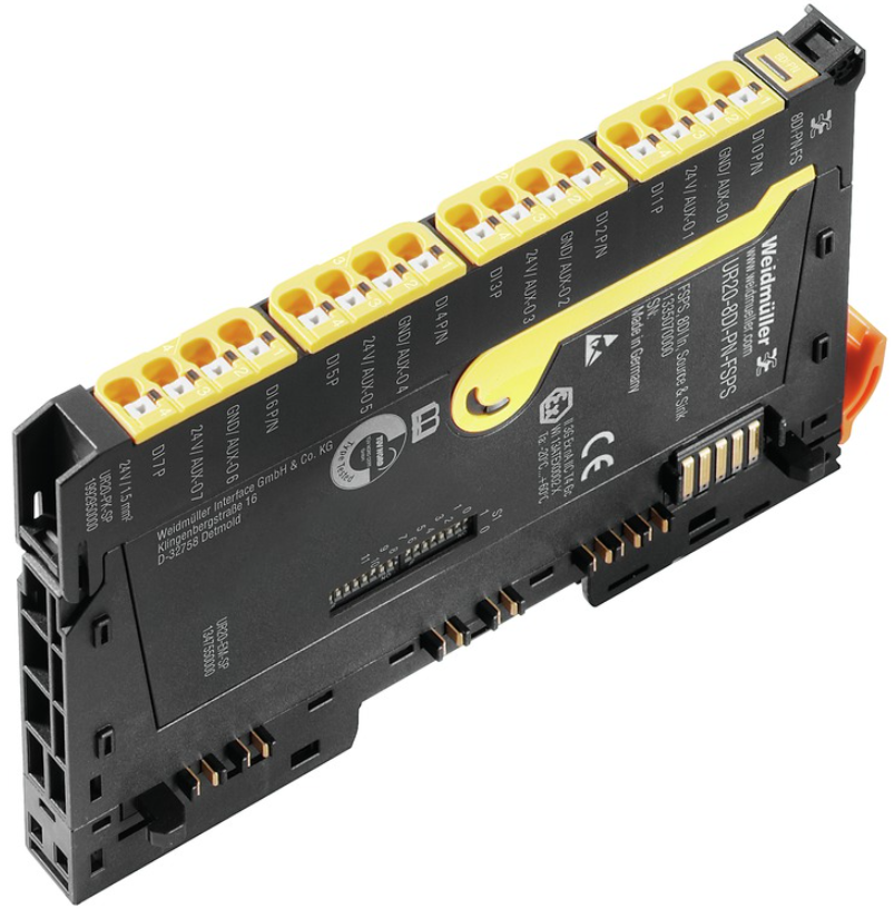
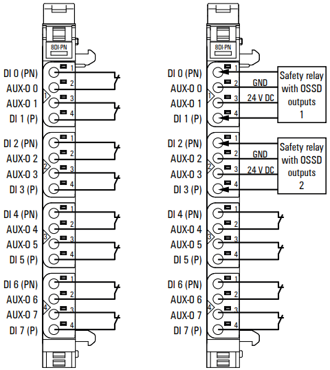
Layout
The test pulse check of an input can be parameterised as cross-circuit detection between input signals and supply voltage, between different input signals or between other signals.
The input is therefore only active when the signal of the dedicated auxiliary output is pending.
If a safety relay with an OSSD output that generates its own test pulse is connected, the test pulse must be disabled.
Safety sensors connected in dual-channel mode (category 4 safety architecture according to DIN EN ISO 13849) must be assigned PN and P inputs on one connector.
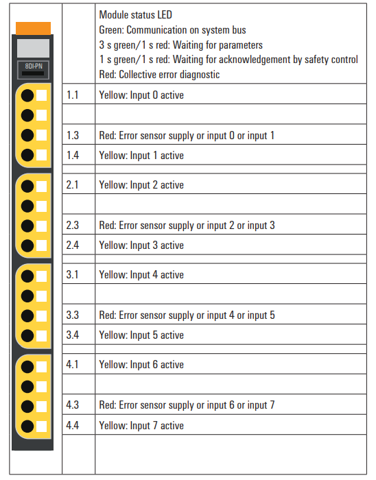
LED
This is the LED status of the UR20-8DI-PN-FSPS-V2.
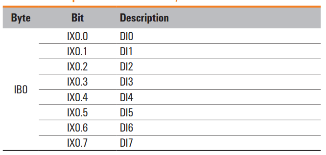
Mapping
This is the Mapping of the UR20-8DI-PN-FSPS-V2?
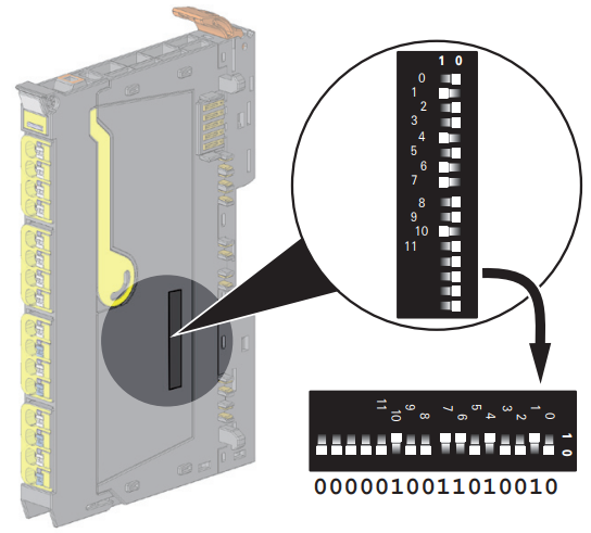
DIP Switch
This DIP switch is used to set the Profisafe address of the UR20-8DI-PN-FSPS-V2.
Implementation
Weidmueller Side
To use Profinet and Profisafe with Weidmuller’s Coupler, you need to download the tools from the Weidmuller Home Page.
Download GSDML File
Download the GSDML File for UR20-FBC-PN-IRT-V2 from the Link below.
https://catalog.weidmueller.com/catalog/Start.do?localeId=en&ObjectID=2566380000

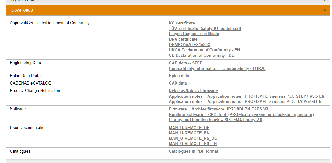
CPD-Tool_(PROFIsafe_parameter-checksum-generator)
To use Profisafe with UR20-8DI-PN-FSPS-V2, download and install the Check-Sum tool for parameters.
https://catalog.weidmueller.com/catalog/Start.do?localeId=en&ObjectID=2464590000
Beckhoff Side
The next step is to build the Beckhoff side.
Install GSDML File
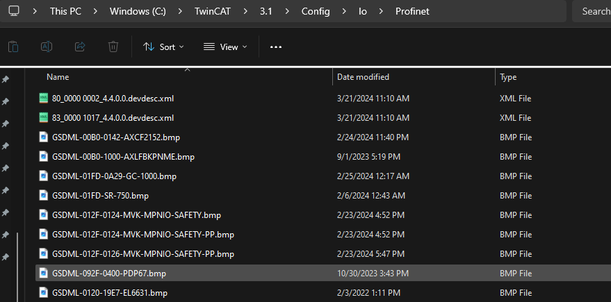
Store the UR20-FBC-PN-IRT-V2 GSDML File downloaded earlier in the following Directory.
C:\TwinCAT\3.1\Config\Io\Profinet
Add EtherCAT Master
To add an EtherCAT Master, go to I/O>Devices>Add New Item.
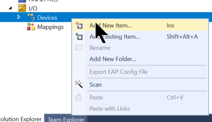
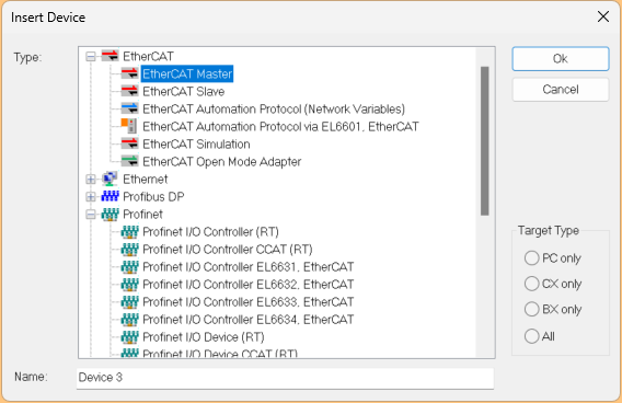
Add EtherCAT>EtherCAT Master.
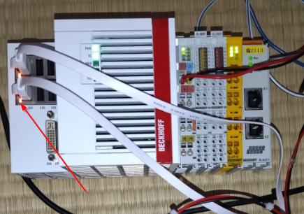
Ethernet Adapter
Configure the Ethernet Interface to be used as EtherCAT Master on the CX5140.
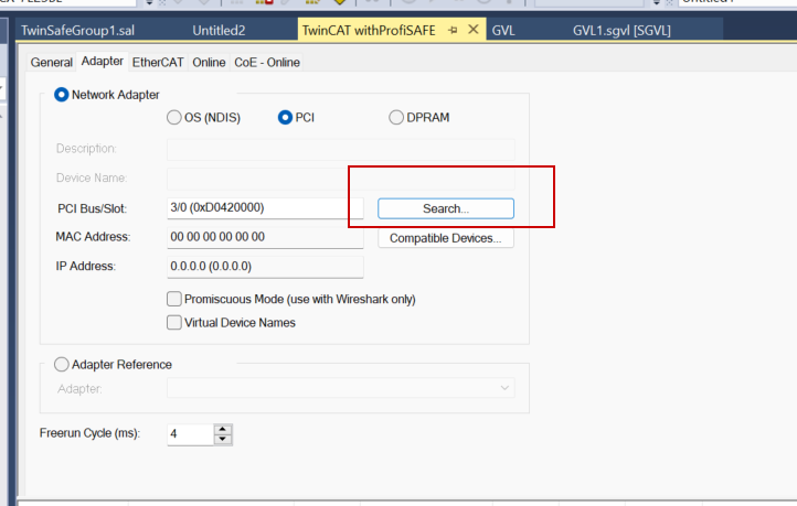
This time, select PCI Bus as you want to communicate PROFIsafe via EL6910.
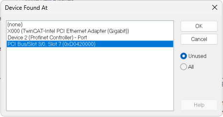
PCI Bus corresponds to the E-BUS next to the CX5140.
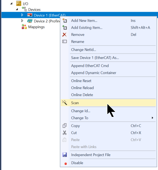
Scan Network
Right-click on EtherCAT Master>Scan to search for EtherCAT Slave.
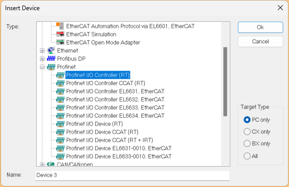
Add Profinet Master
Next, to add a Profinet Master, go to Devices>Add New Item.
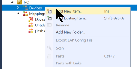
Select Profinet>Profinet I/O Controller (RT) and press >Ok.
Configure Adapter
Configure the Ethernet Interface to be used as Profinet.
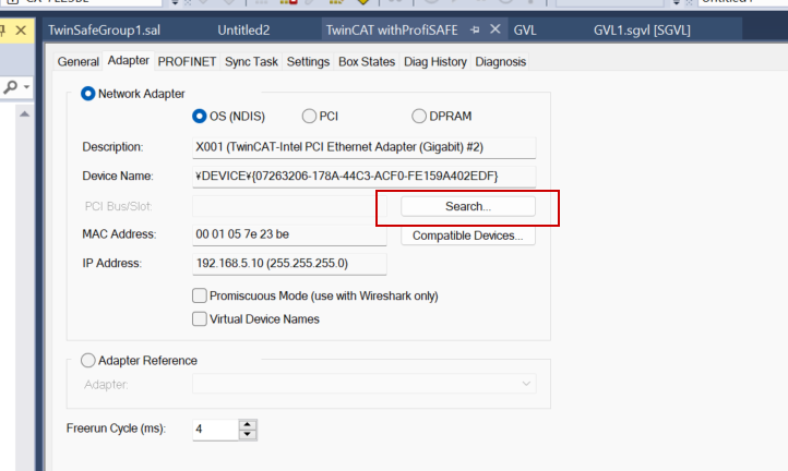
This article sets out X001.
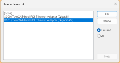
X001 is the second Ethernet Port on the CX5140.
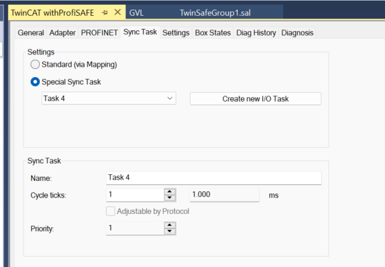
Sync Task
Configure Profinet’s execution tasks to suit your application.
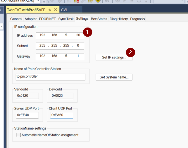
IP Setting
Next, set the IP address of the PROFINET Controller and click ‘Set IP Settings’ to apply the settings.
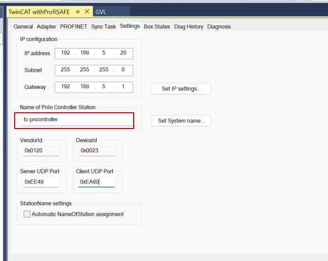
Controller Name
Set the Profinet Controller name to an easily recognisable name.
Configure Coupler
The next step is to add the Hardware Configuration of the Profinet CouplerUR20-FBC-PN-IRT-V2 to the TwinCAT project.

Add Coupler
Add UR20-FBC-PN-IRT-V2 Profinet Coupler.
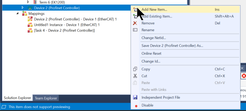
Right-click the Profinet Controller you have just added>Add New Item.
Select Weidmuller>I/O>UR20 System and proceed with >Ok.
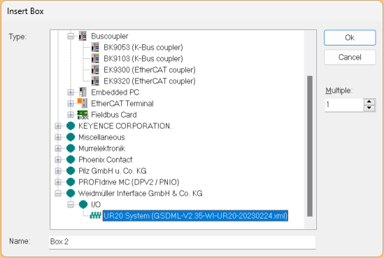
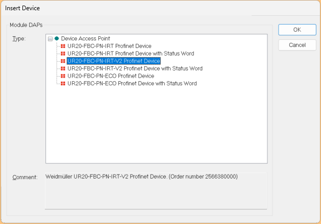
Add the UR20-FBC-PN-IRT-V2 used in this article.
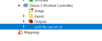
Done!
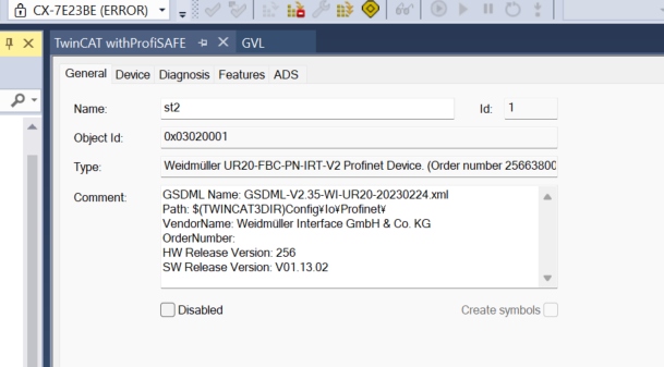
Station Name
Set the device name of the UR20-FBC-PN-IRT-V2 in the General Tab.
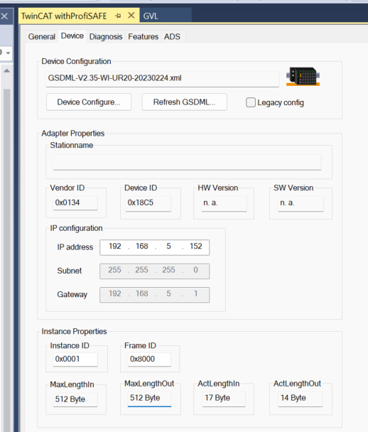
Device
Set the IP address of the UR20-FBC-PN-IRT-V2 Coupler in Device Tab.
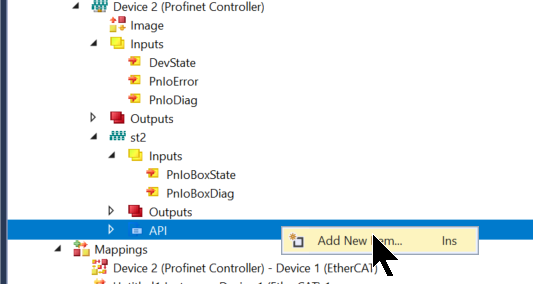
Configur Slot
Now that you have added the UR20-FBC-PN-IRT-V2 to the Profinet network, the next step is to build the module installed next to it: right-click on UR20-FBC-PN-IRT-V2>Add New Item.
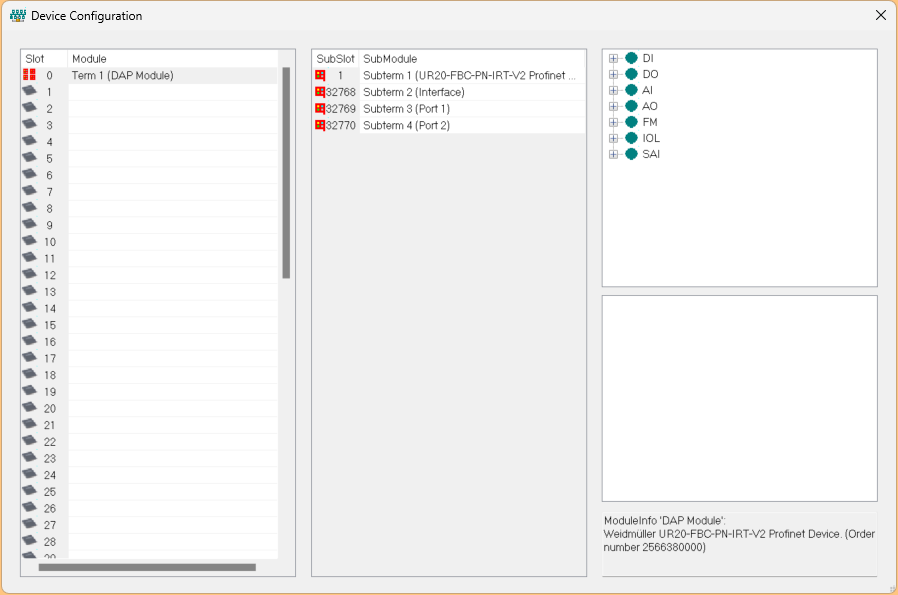
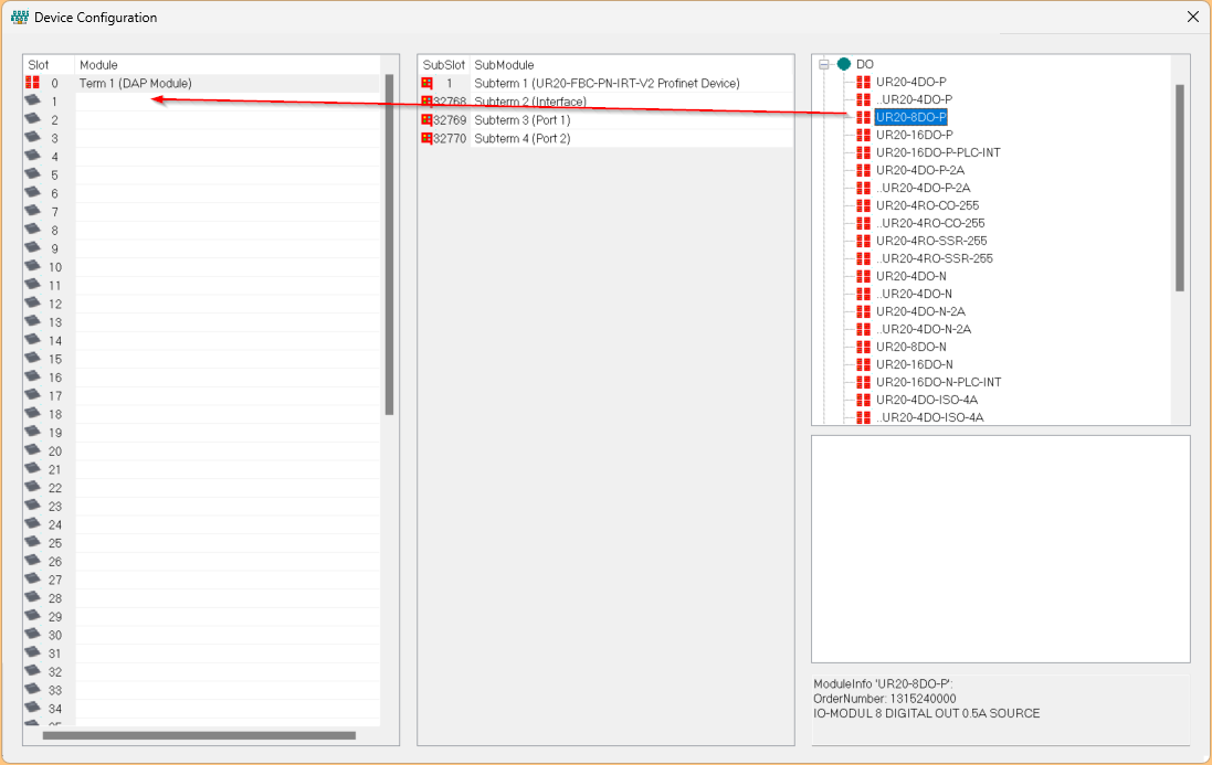
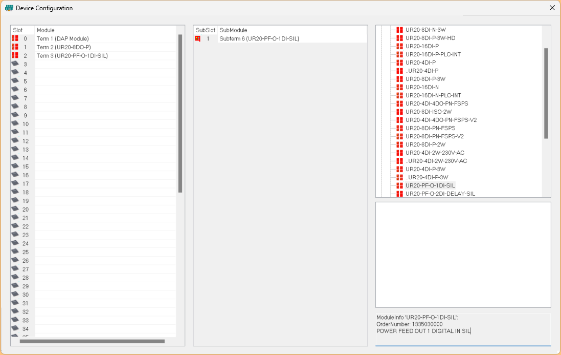
This is the Device Configuration screen of Profinet.
Add Module1
Slot 1 has UR20-8DO-P installed.
Choose DO>UR20-8DO-P and add it to Slot 1.
Done!
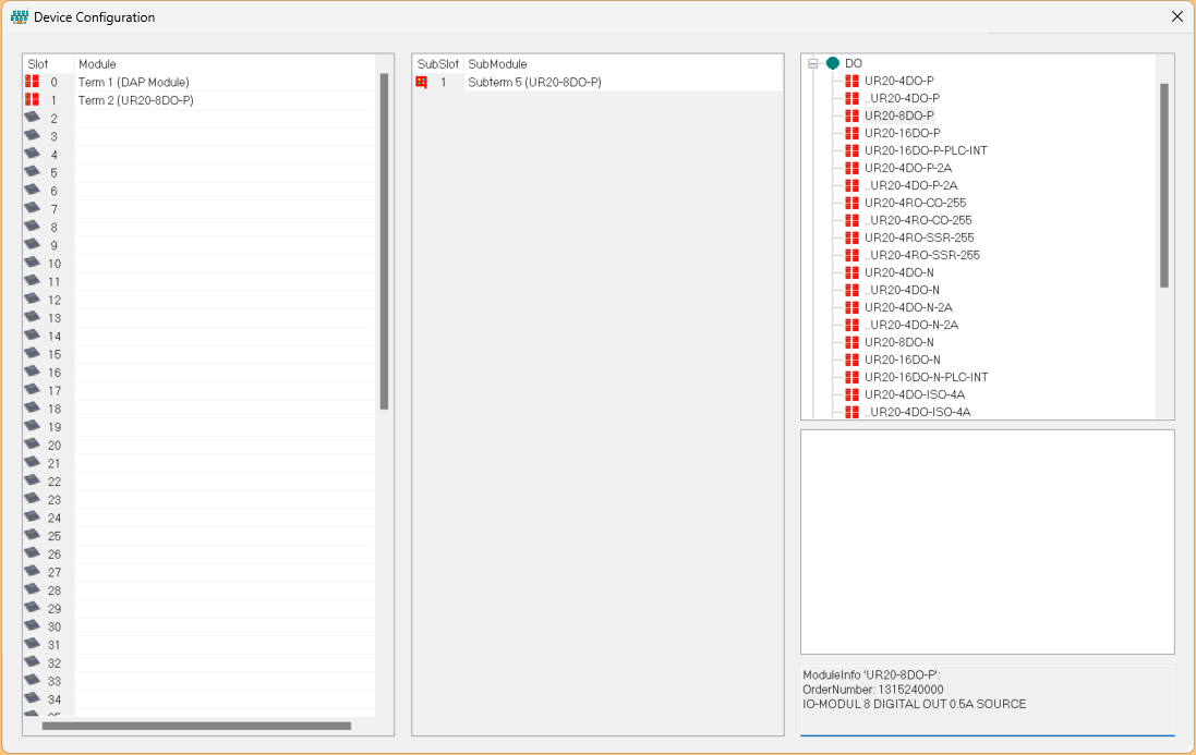
Add Module2
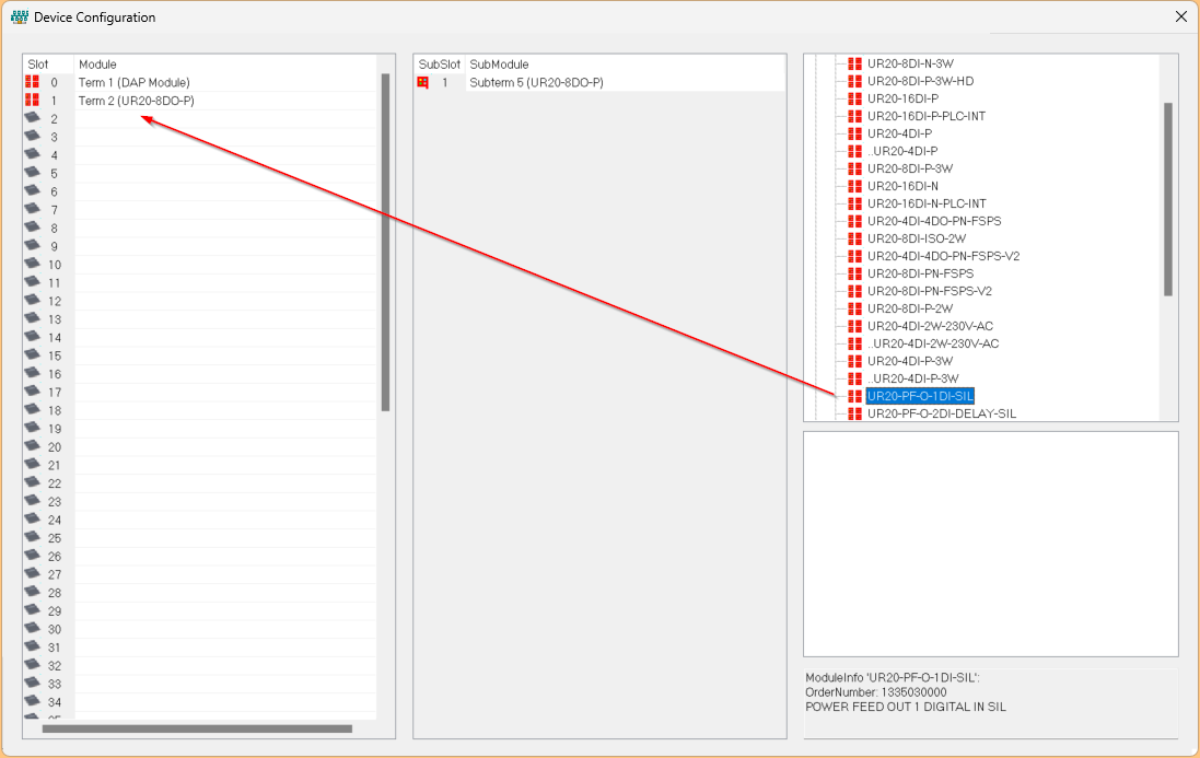
Slot 2 has UR20-PF-O-1DI-SIL installed.

Choose DI>UR20-PF-O-1DI-SIL and add it to Slot 2.
Done!
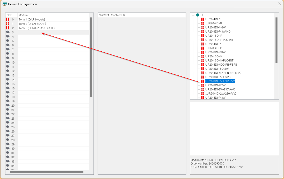
Add Module3
UR20-8DI-PN-FSPS-V2 is installed in Slot 3.

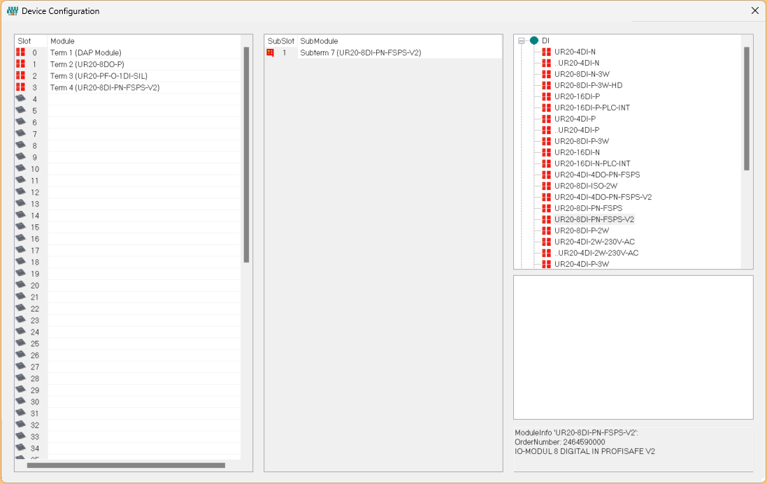
Choose DI>UR20-8DI-PN-FSPS-V2 and add it to Slot 3.
Done!
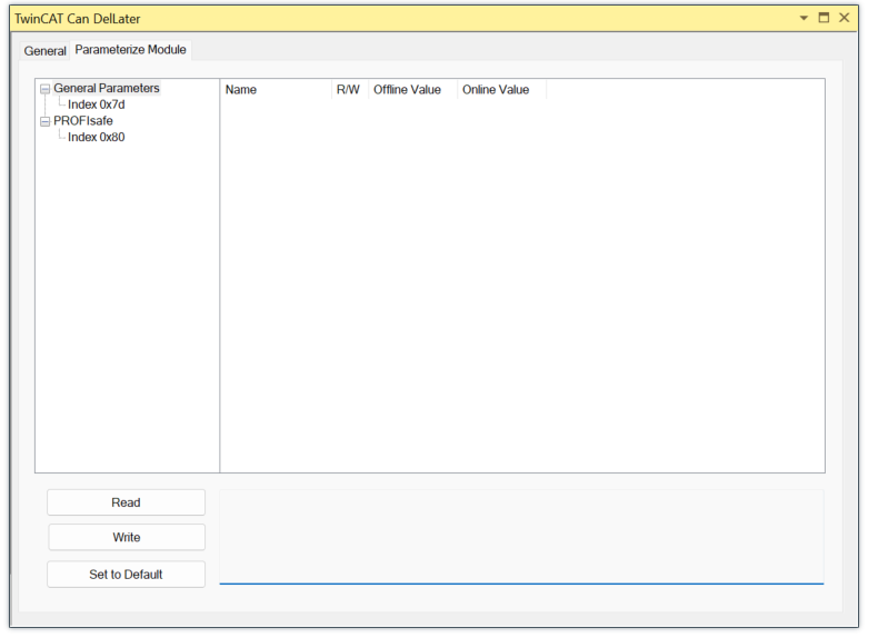
Parameters
Now we can set the parameters of the UR20-8DI-PN-FSPS-V2.
Open the Parameterize Module Tab to set the module.
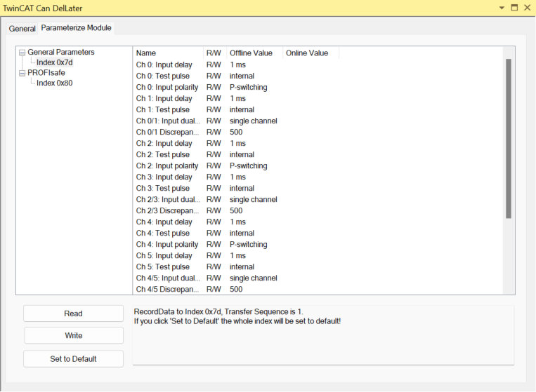
General Parameters
General Parameters are the input parameters for each channel and should be set according to your application.
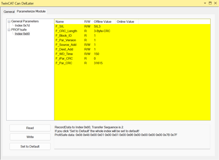
PROFIsafe
This is a parameter for PROFIsafe communication.
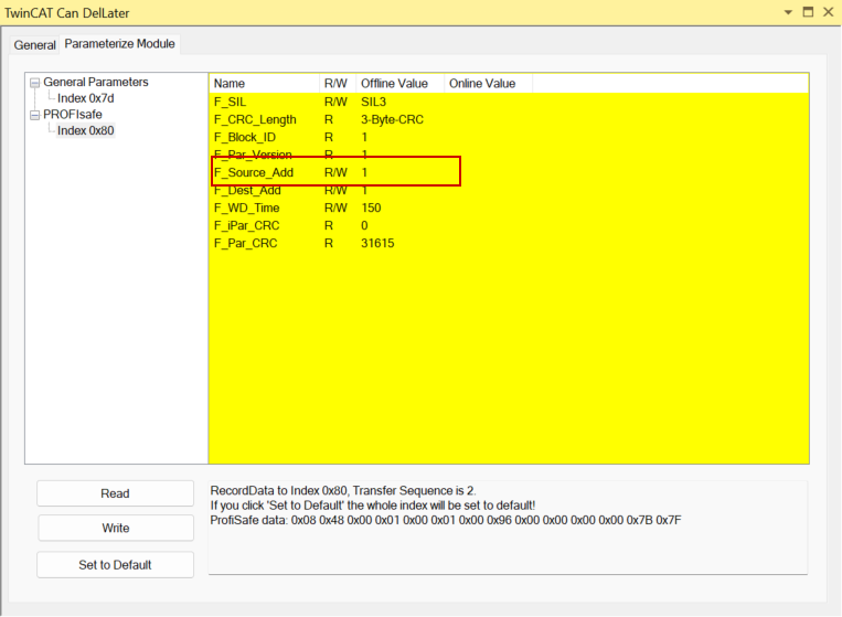
F_Source_Add
F_Source_Add becomes the FSoE address of the EL6910, we will set 1 in this time.
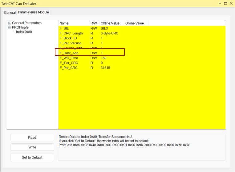
F_Dest_Add
F_Dest_Add should be set to the PROFIsafe address set on the UR20-8DI-PN-FSPS-V2 DIP switch.
F_WD_Time
F_WD_Time is the Watchdog setting.

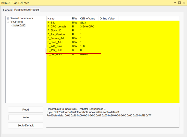
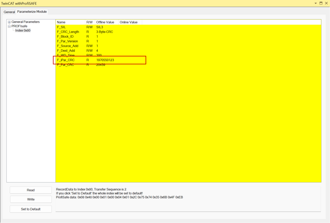
F_iPar_CRC
The last step is to set the CRC value of the parameter.
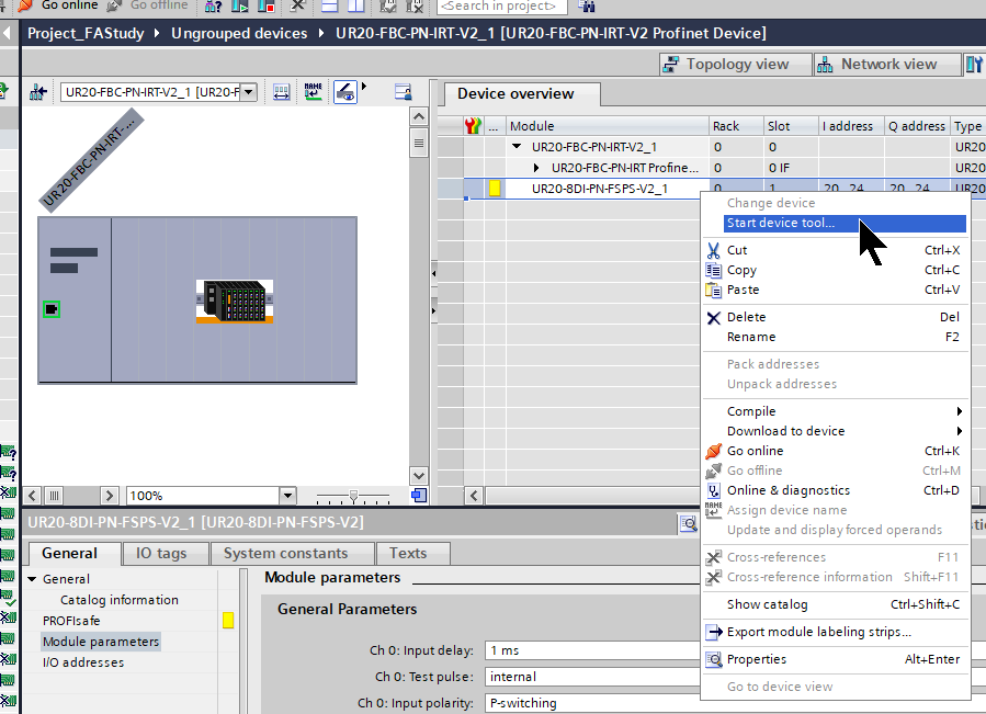
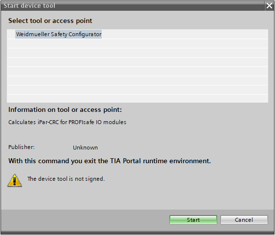
Weidmueller was only provided with the Parameters CRC tool specifically for Siemens’ TIA, so right-click on the UR20 Profinet Coupler with Weidmueller’s UR20-8DI-PN-FSPS-V2 added to the TIA>Start Click on device tool.
Proceed with Start.
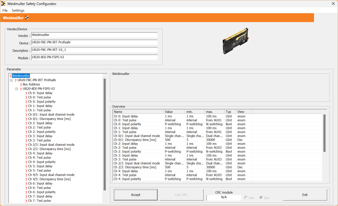
This is the Weidmuller Safety Configurator.
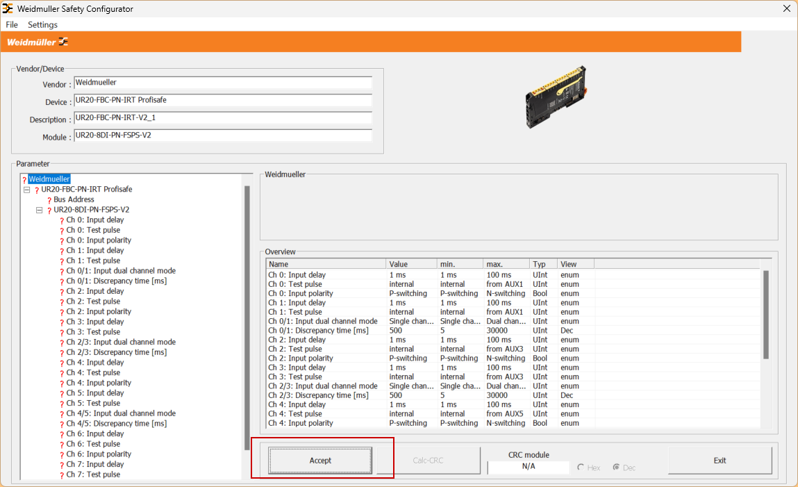
Accept the Parameters.
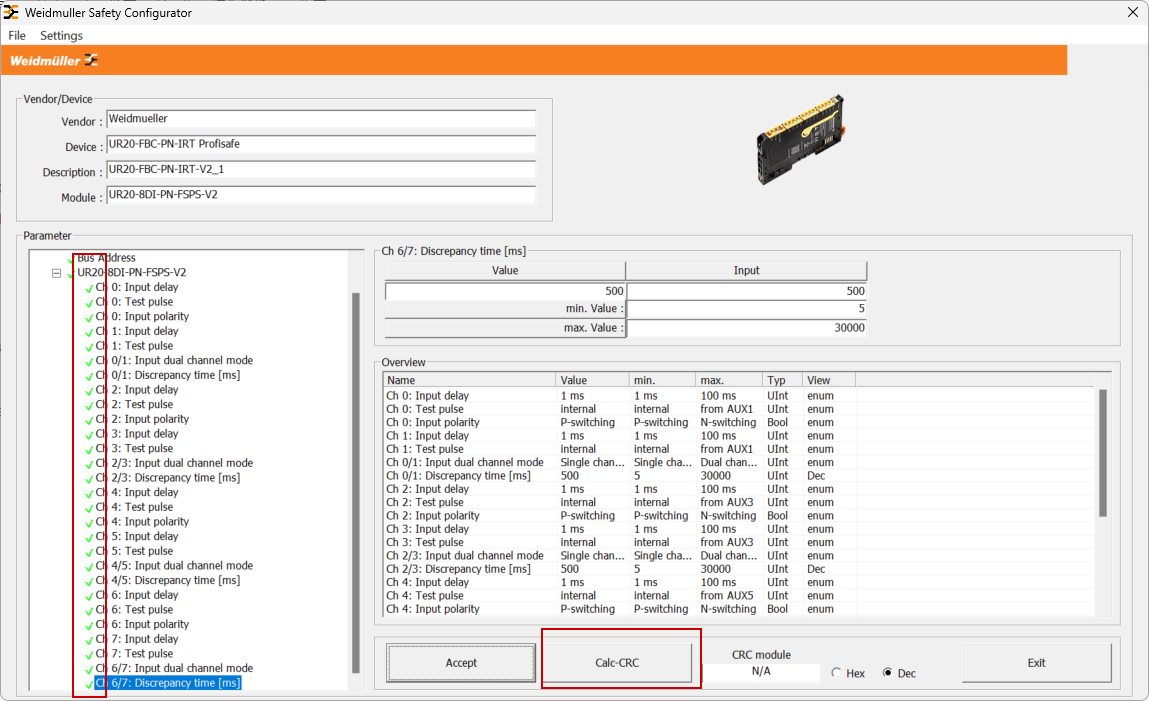
Set up all parameters and click on ‘Calc CRC’ to calculate the parameter CRC values for the module.
Done!The display can be switched to show the CRC value as Hex or Dec.
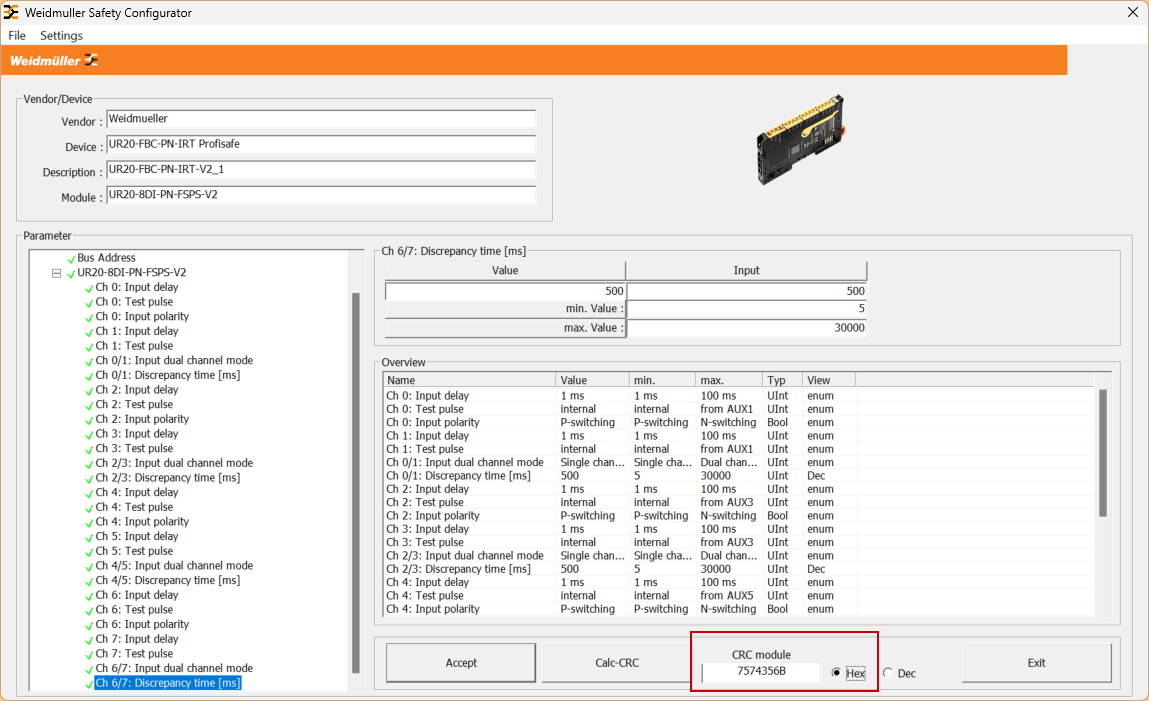
The CRC value is pasted into F_iPar_CRC.
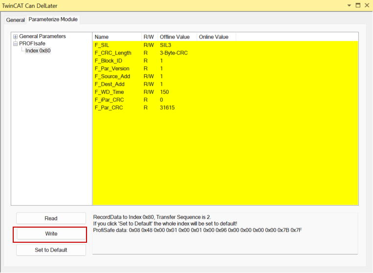
Write
Click Write to write the parameters to the module.
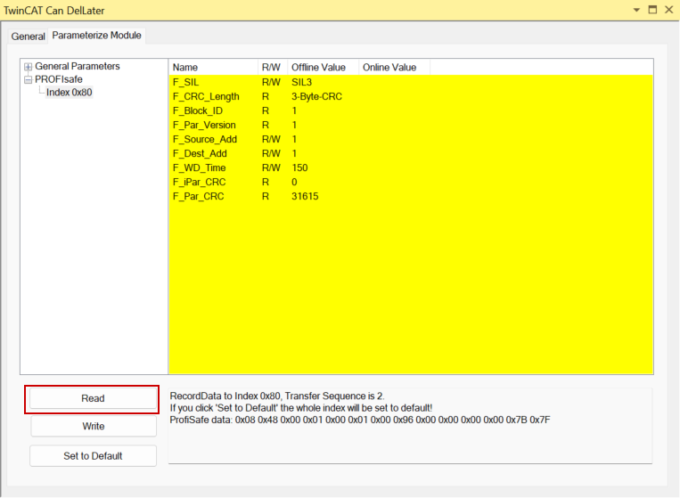
Read
Read to see if the parameters have been written.
Add PLC
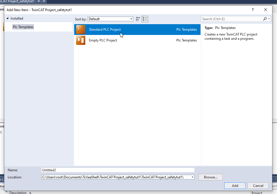
Create a PLC Project at PLC>Add New Item.
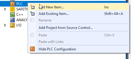
You can do this by selecting Standard PLC Project and >Add.
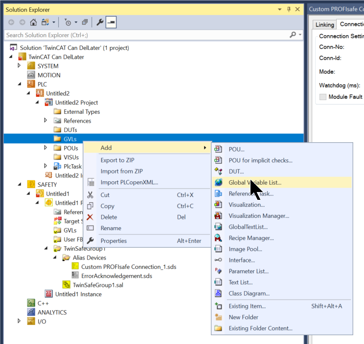
Add GVL
GVLs>Add>Global Variable List.
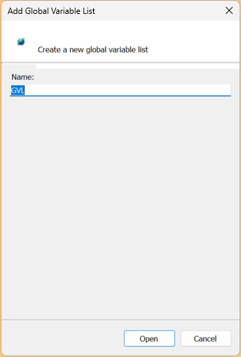
Set the Global Variable List name.
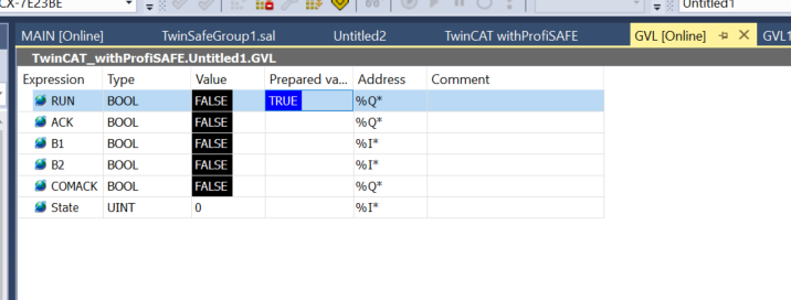
Define a Process IO to exchange data with the EL6910 as shown in the diagram below.
| {attribute ‘qualified_only’} VAR_GLOBAL RUN AT %Q*:BOOL; ACK AT %Q*:BOOL; B1 AT %I*:BOOL; B2 AT %I*:BOOL; COMACK AT %Q*:BOOL; State AT %I*:UINT; END_VAR |
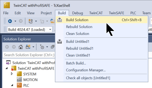
Build
Build the project using Build>Build Solution.
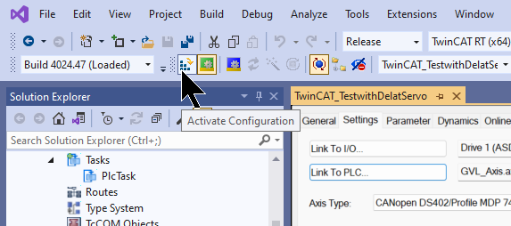
Active Configuration
Click Active Configuration and Download the project to Runtime once.
OK to proceed.
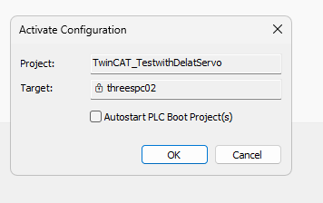
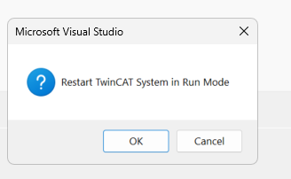
OK softens the TwinCAT Runtime to Run Mode.
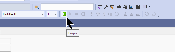
Login
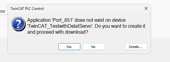
Download the programme in Login.
Proceed with Yes.
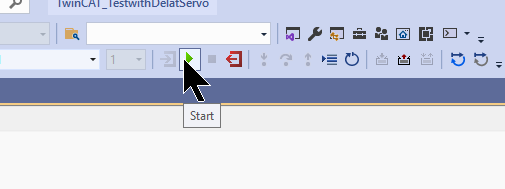
Start
Finally, the Start button executes the Runtime programme.
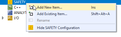
Add Safety Project
SAFETY>Right click>Add New Item.
Select TwinCAT Safety Project Preconfigured EndAck >Add.
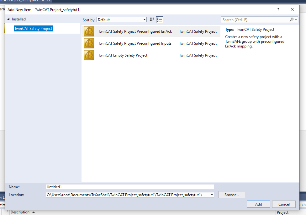
Since the EL6910 is used, select Hardware Safety PLC for Target >OK.
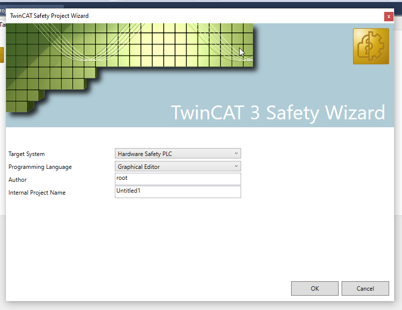
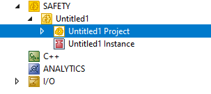
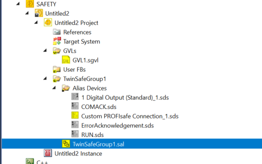
Safety Project has been added.
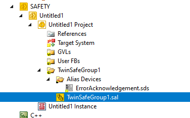
The TwinSAFEGroup is where the safety programme is set up.
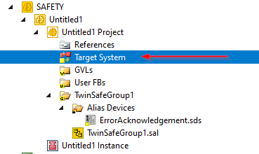
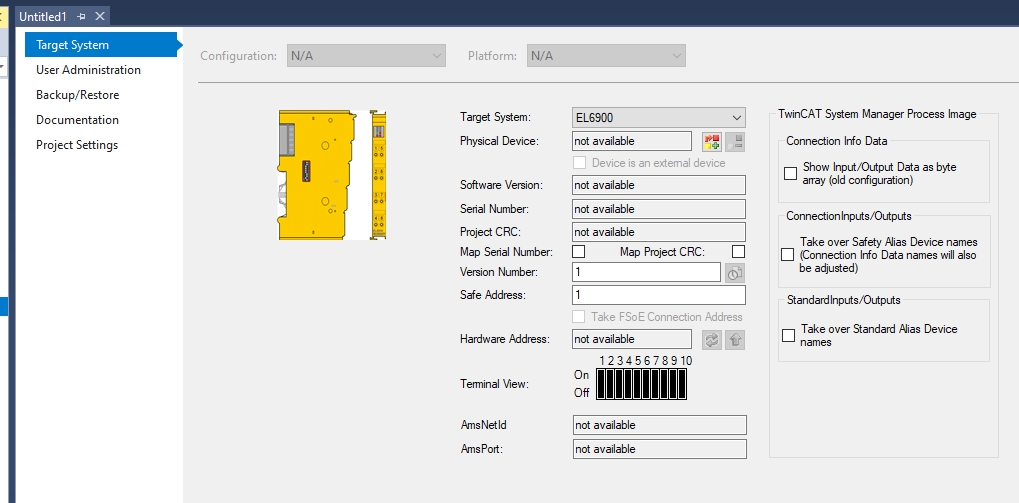
Set Target System
First, set the Target System in the Safety Project. This time it is the EL6910 – click on the Target System item.
The TwinCAT side changes to the Target configuration screen.
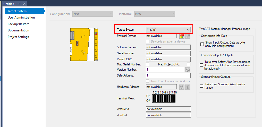
Select Target System
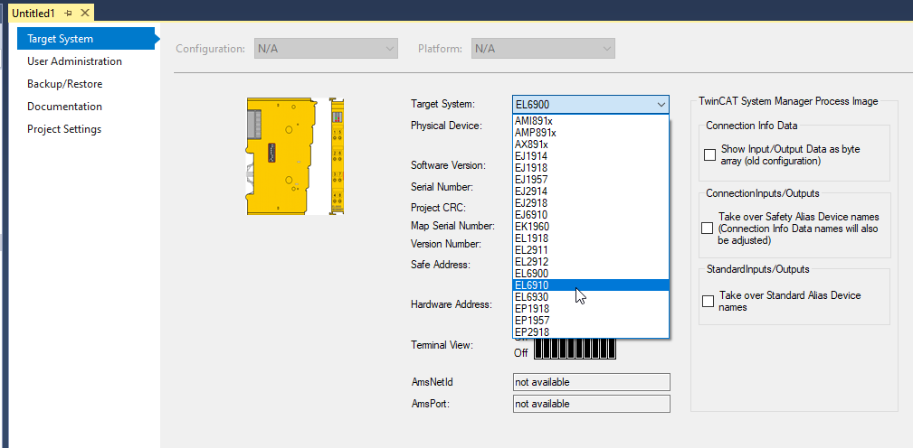
First select the Target System – Default is EL69100 and click on Drop List in Target System.
Select EL6910.
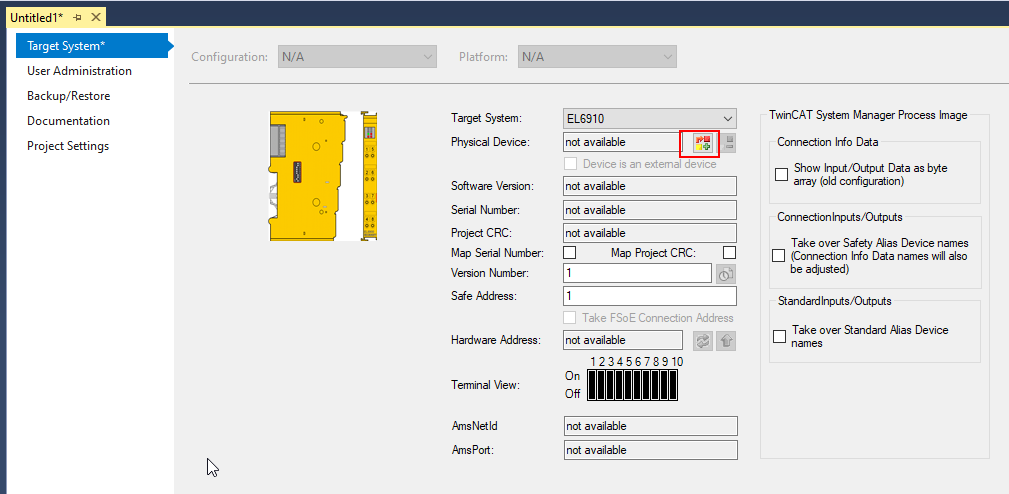
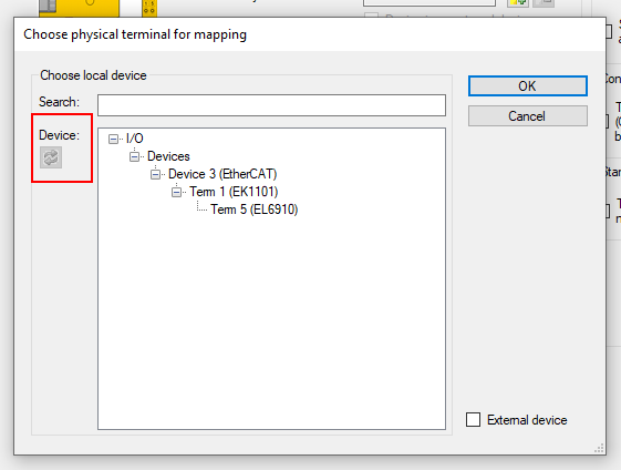
Set Physical Devices
The next step is to link the Target System in the Safety Project to the actual EL6910.
Click on the button in the red frame.
If you cannot find the device, check that the device type is correct and that it is switched on, then click the Reflesh button in the red frame and scan the Target System once more.
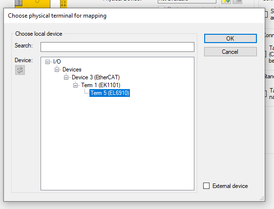
Select EL6910 >OK.
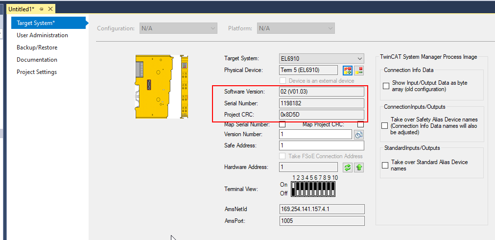
Now Target System has changed to EL6910 and can read in the Software Version/Serial Number and Project CRC of the actual machine.
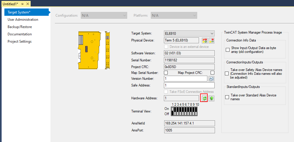
Update Hardware Address
Update the Hardware Address again, just to be sure.
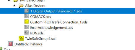
Add Digital Inputs/Outputs
Add the following variables to Alias Devices.
- Digital Inputs, Safety Group Run signal
- Digital Inputs, Error Ack signal
- Digital Inputs, COM Ack signal
- Digital Outputs, signal to feed back to TwinCAT project
Add PROFISafe Connection
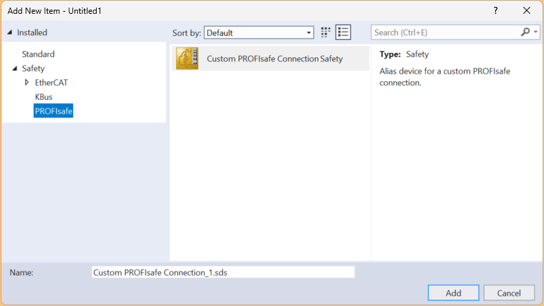
The next step is to add the PROFIsafe Connection of UR20-8DI-PN-FSPS-V2 to Alias Devices.
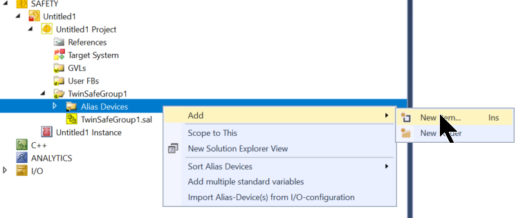
Select Safety>PROFIsafe>Custom PROFIsafe Connection Safety>Add.
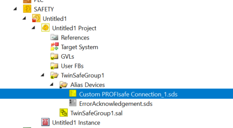
Done!Custom PROFIsafe Connection has been added.
Linking
Now simply configure it in the same way as the usual FSoE Slave.
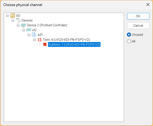
Physical Device
Click on the button with the red border under Linking Tab>Physical Device.
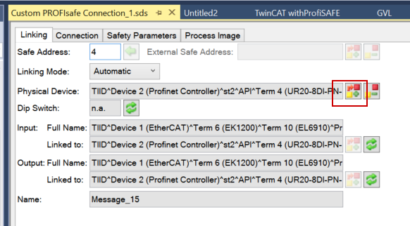
The UR20-8DI-PN-FSPS-V2 you have just added appears and is added with OK.
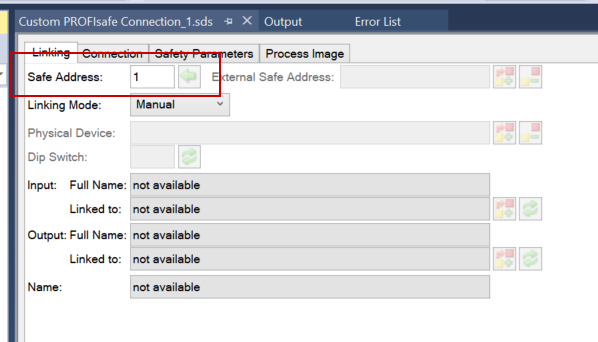
Safety Address
The Safety Address corresponds to the PROFIsafe address of the UR20-8DI-PN-FSPS-V2.
Connection
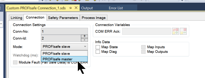
Next, open the Connection Tab.
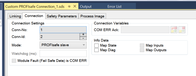
Mode
Set Mode to PROFIsafe Master.
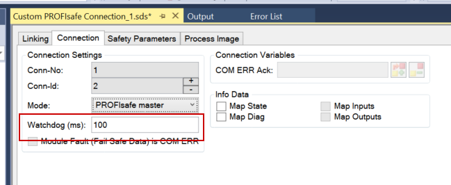
Watchdog
Set the Watchdog to match the application.
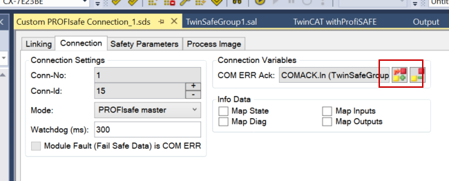
COM Err Ack
This is an Ack Signal for communication errors.
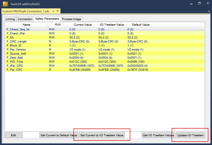
Safety Parameters
The next step is to set the Profisafe parameters.
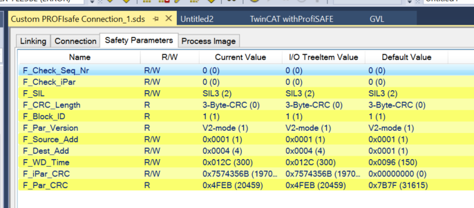
F_Dest_Add should be set to match the DIP switch set on the UR20-8DI-PN-FSPS-V2.
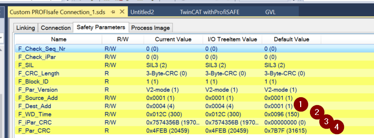
Finally, transfer the current Safety Parameters.
Safety GVL
Now define the Safety variable.
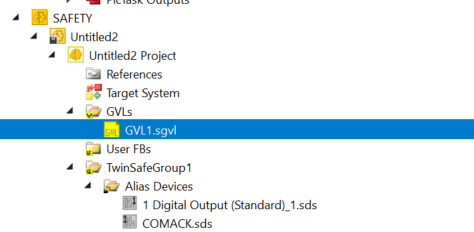
Safety input and Mapping of UR20-8DI-PN-FSPS-V2.
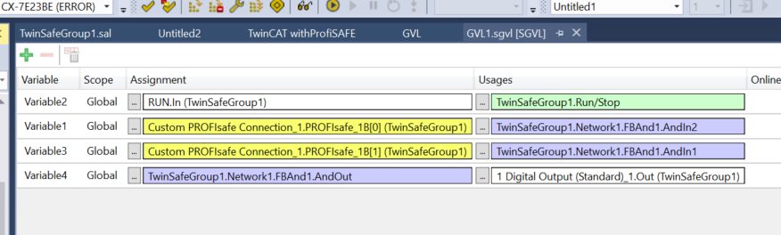
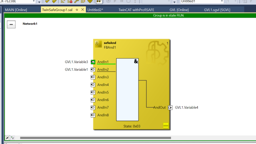
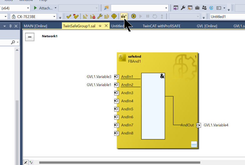
Safety Group
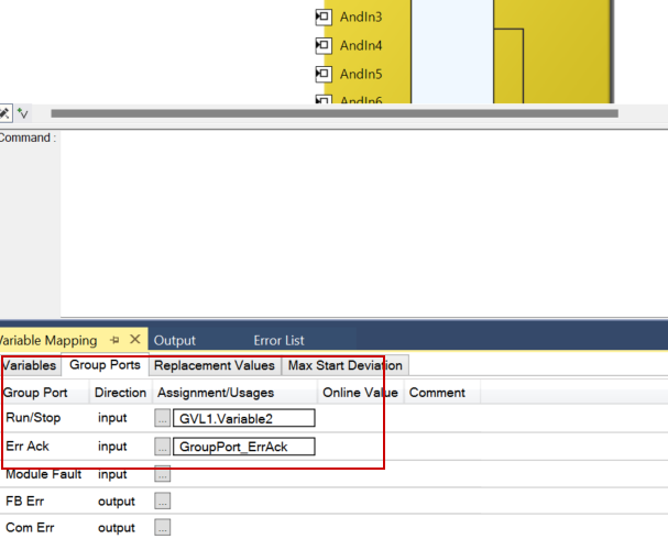
The next step is to create a simple Safety program.
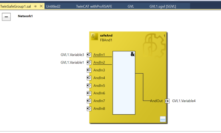
Note that Run/Stop and Err Ack are mapped to the Digital Inputs you have just added.
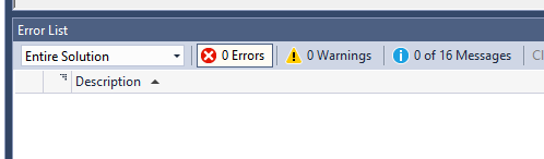
Verify
The last step is to compile the safety project.
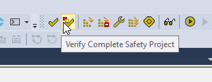
Done!
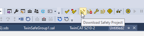
Download Safety Project
Download the safety application at “Download Safety Project”.
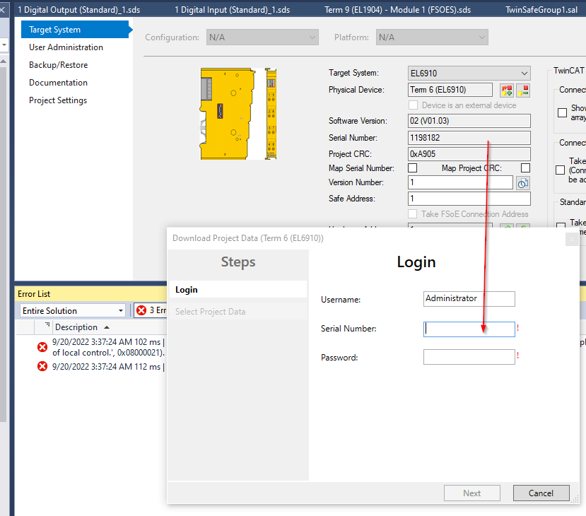
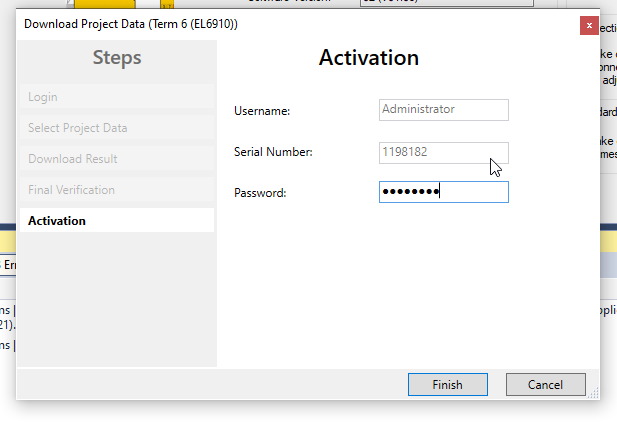
The Login screen is displayed, where Username is Administrator.
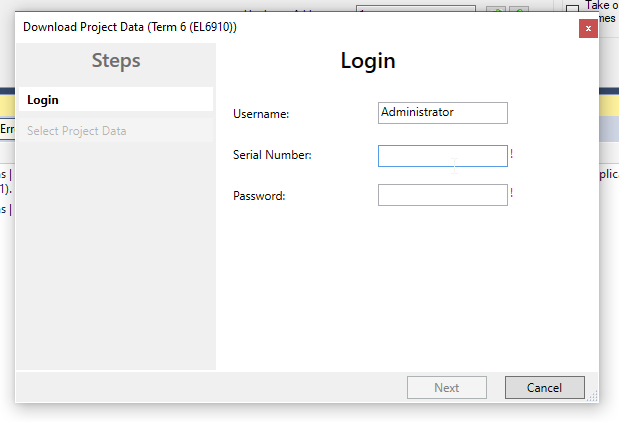
Next is the Serial Number.
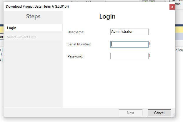
Enter the Serial Number as it appears on the Target System screen.
今回のモジュールは1198182なのでSerial NumberのFieldは1198182にします。
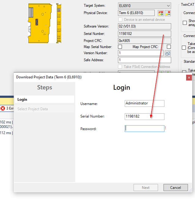
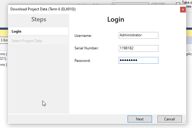
The last Password Default is TwinSAFE.
Enter all of them and press Next to proceed.
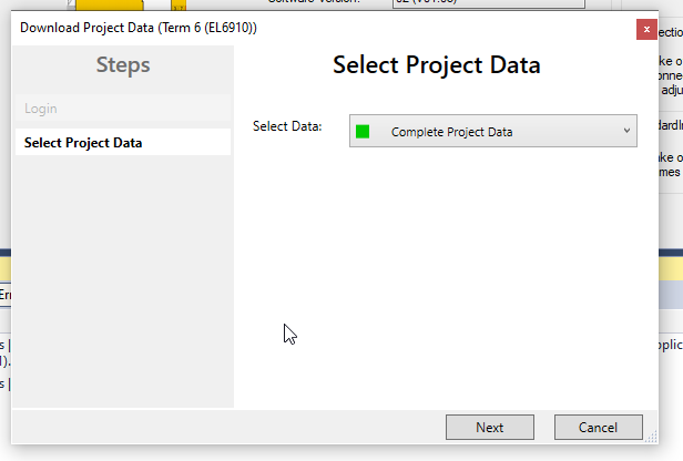
If the information entered is correct, proceed to the Select Project Data screen.
Select Data is Next with Complete Project Data.
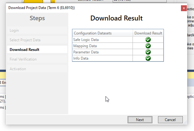
Project successfully Downloaded, proceed with Next.
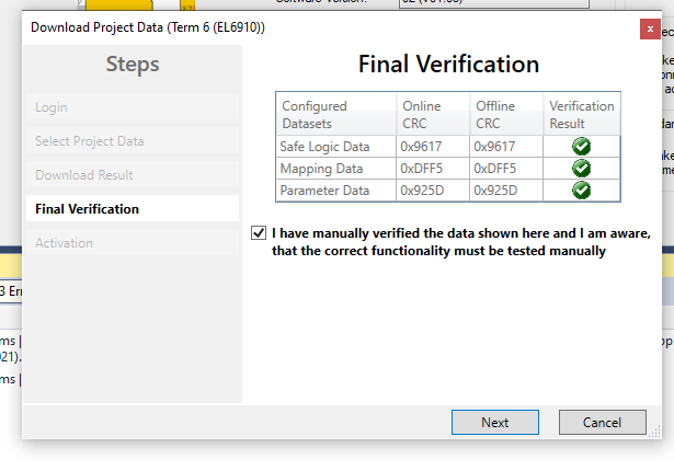
Finally, put Checkbox and press Next.
Enter the Password again to activate the Safety Application.
Default Password is TwinSAFE.
Result
Set the RUN Flag to TRUE and shift the Safety programme into RUN mode.
Monitor safety programmes.
The safety program is in error status.
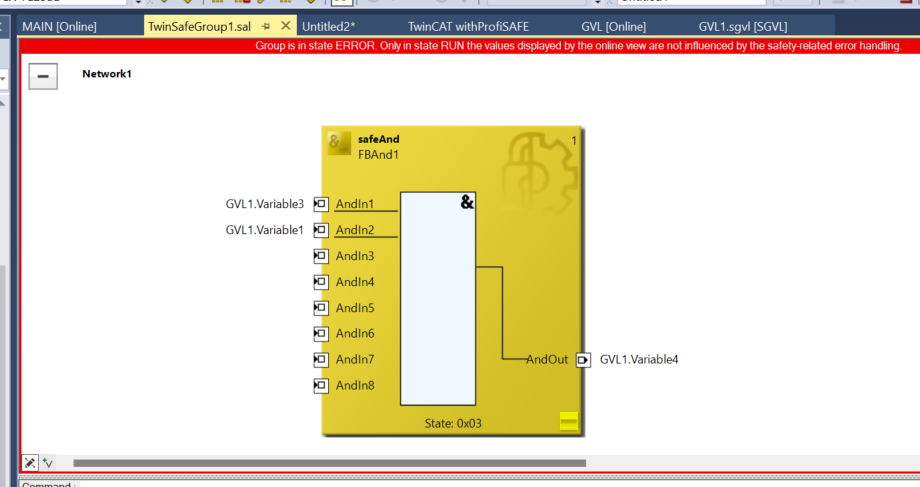
Turn TRUE for the ACK and COMACK and reset the error.

Done!The Safety programme is currently error-free; the IO status has also been checked!