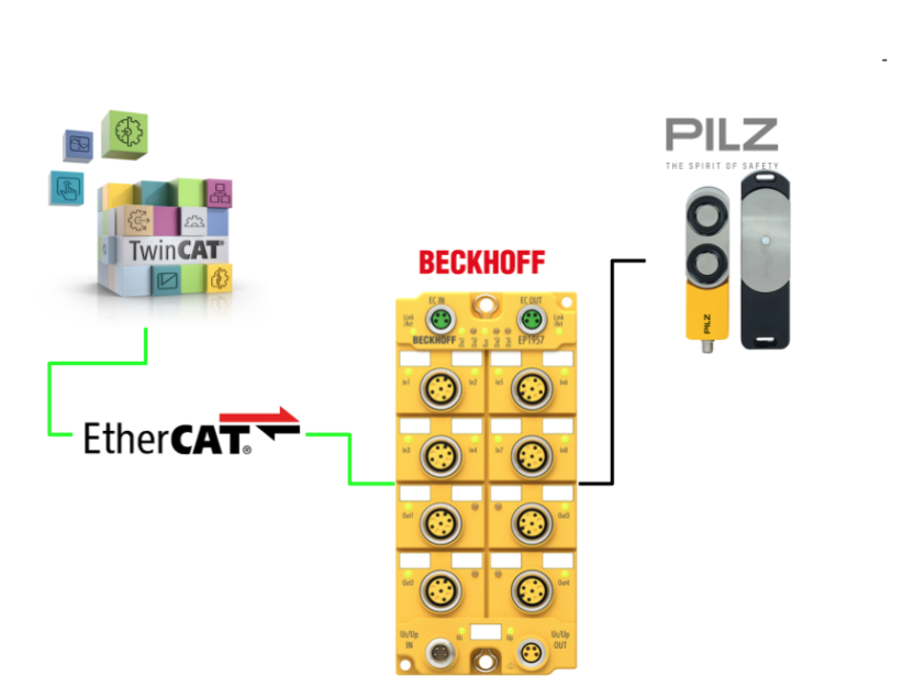
In this article, we will use the Local I/O of Beckhoff’s EP1957-0022, connect it to a Pilz Door Lock switch, and build a simple safety program.
Come on, let’s enjoy FA.
Reference Link
Implementation
Pilz Side
The door locks used in this article will be Pilz door locks.
Reference Link
Please refer to this article for wiring instructions.
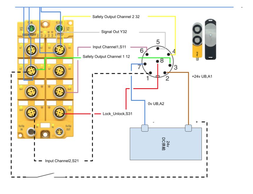
Wiring
Here is the wiring diagram for this article.
Beckhoff Side
Once the Pilz door lock and Gi wiring is complete, the next step is to create a Safety project on the Beckhoff side.
GVL
Add a variable called DoorisLocked to the PLC project. This one feedabcks the current state of the door lock.
| {attribute ‘qualified_only’} VAR_GLOBAL ErrorAck AT %Q*:BOOL; Run AT %Q*:BOOL; DevState AT %I*:UINT; // DoorisLocked AT %I*:BOOL; END_VAR |
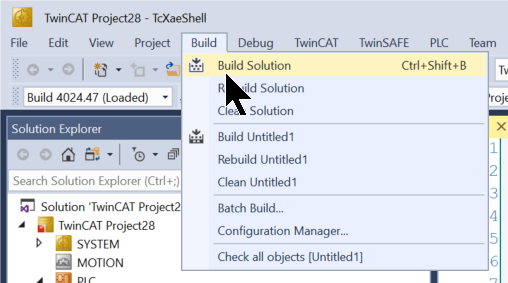
Build
Compile the project under Build>Build Solution.
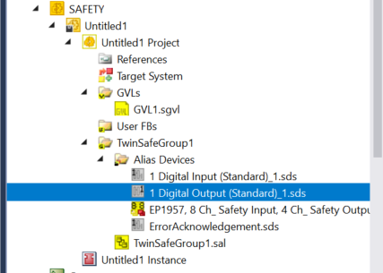
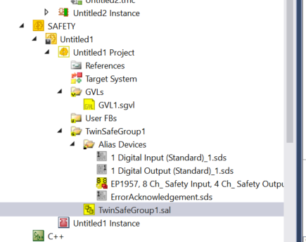
Safety Project
The next step is to change the Safety project.
Alias
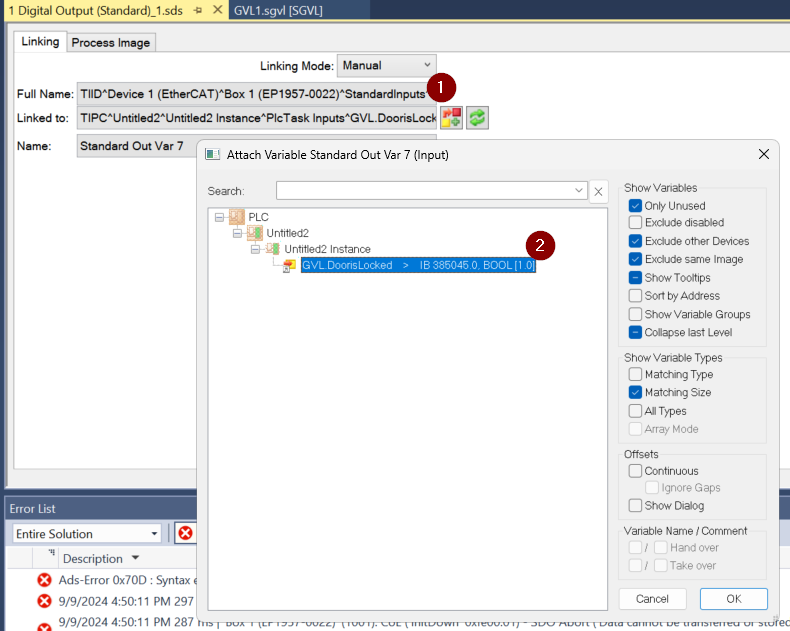
This time we want to check if the door is locked, so we add one digital output to Alias Devices. That output corresponds to the input variable we just defined in GVL in the PLC project.
GVL
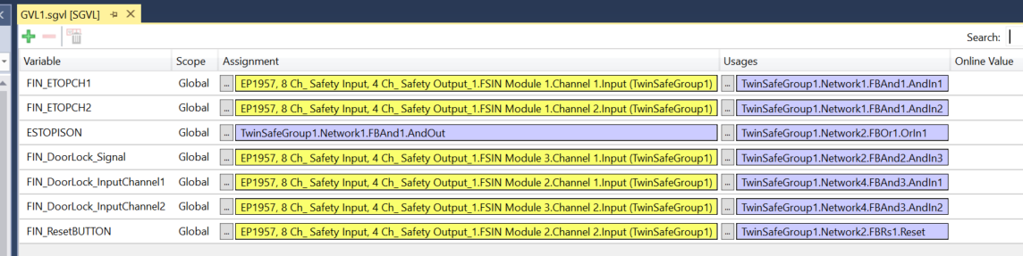
Next, let’s define the variables used in the safety program.
- FIN_ESTOPCH1
- Safety stop input 1
- Safety input module 1 channel 1
- FIN_ESTOPCH2
- Safety stop input 2
- Safety input module 1 channel 2
- FIN_DoorLock_Signal
- Door closed signal
- Safety input module 3 channels 1️.
- FIN_DoorLock_InputChannel1
- Door locked signal 1
- Safety input module 2 channels 1️.
- FIN_DoorLock_InputChannel2
- Door locked signal 2
- Safety input module 2 channel 2
Safety Program
The next step is to create a safety program.
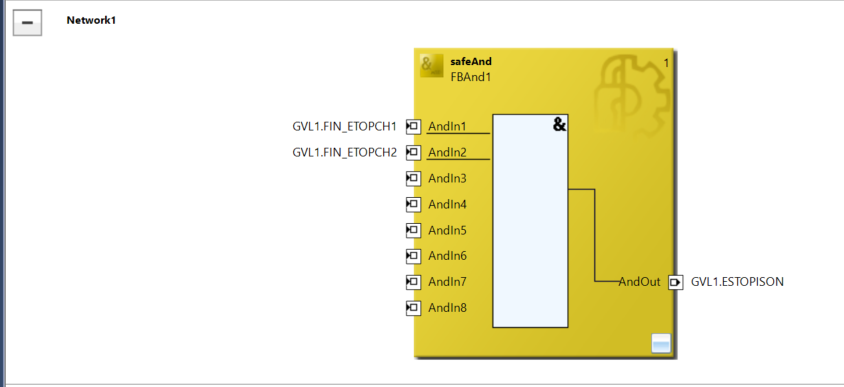
Network1
Network 1 checks if the emergency stop input is True.
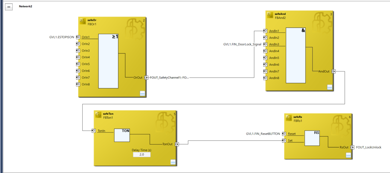
Network2
Network 2 will automatically true the lock signal to the Pilz door lock when the emergency stop input is true. It will then lock after 2 seconds.
It also unlocks the door locks when the reset button is pressed.
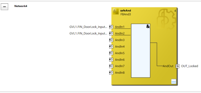
Network3
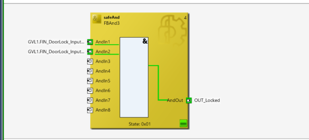
Network 3 actually feeds back the lock status of the door lock to the Normal PLC.
Local Variale
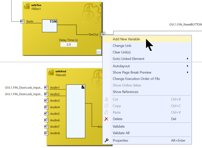
In TwinSAFE, a variable can only be used once, so if you want to use the same signal in multiple places, right-click on the appropriate signal>Add New Variable.
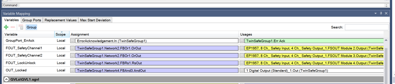
Automatically add Local Safety variables to Variable Mapping.
Verify Safety Project
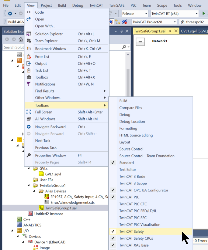
Click View>Toolbars>TwinCAT Safety to display buttons for TwinSAFE.
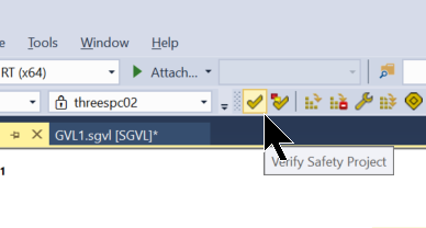
The next step is to compile the safety project with Verify Safety Project.
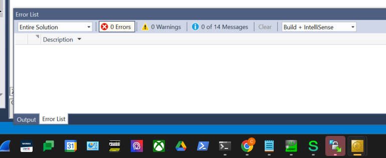
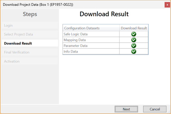
Done!There are no errors in the compiled results.
Download
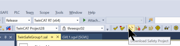
Download the safety program to EP1957-0022 at Download Safety Project.
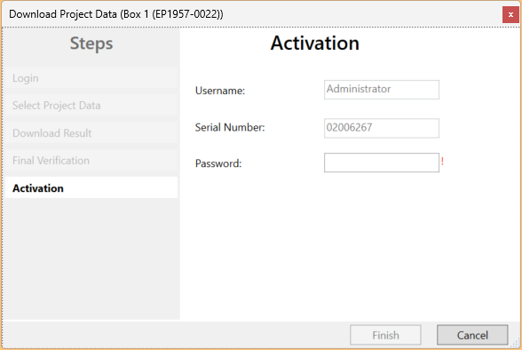
Default Username is Administrator and Default Password is TwinSAFE.
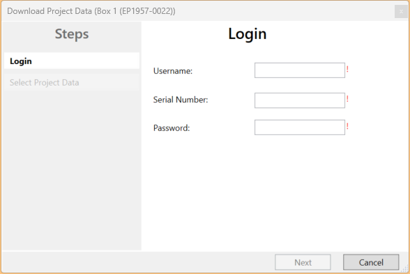
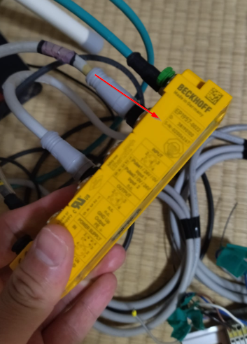
The serial number of EP1957-0022 is next to the actual machine.
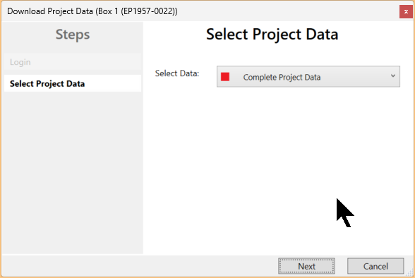
Select Complete Project Data and press Next to proceed.
Proceed with Next.
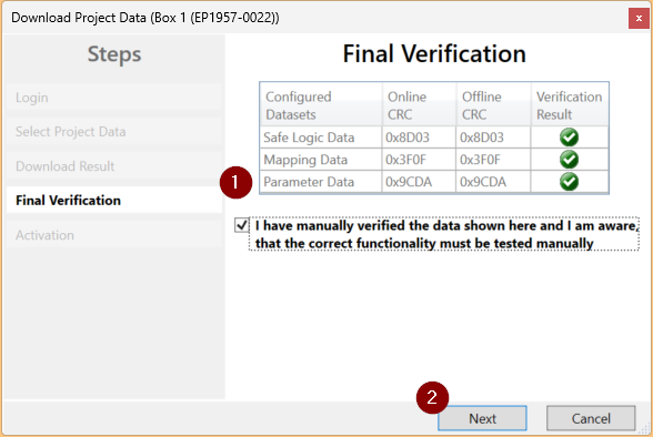
Check the Check Box and press Next to proceed.
Enter your password one last time.
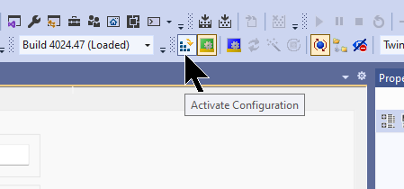
Activate Configuration
Press Activate Cofiguration to Download the Hardware Configuration.
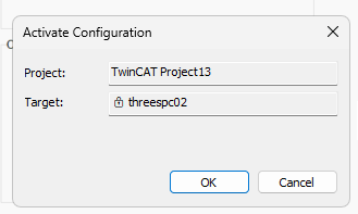
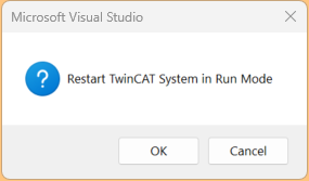
OK to proceed.
Switch TwinCAT Runtime to Run Mode.
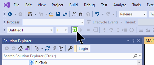
Login
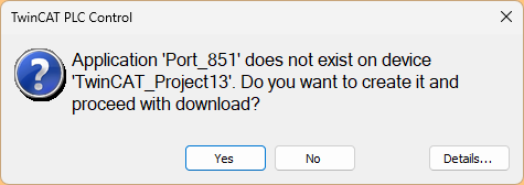
Download the program in Login.
Proceed with Yes.
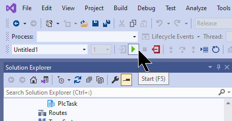
Start
Finally, start TwinCAT Runtime with the hStart button.
Result
Click on Show Online Data to monitor the safety program.
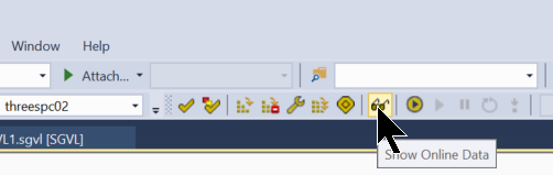
Safety Group is now RUN.
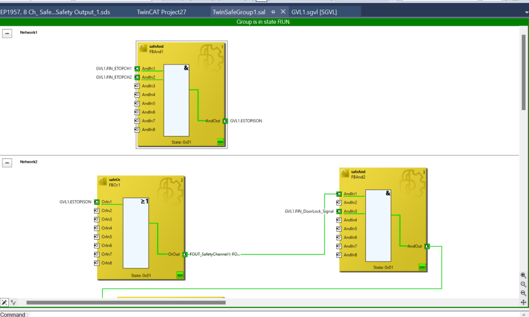
When the door is locked, the signal is fed back to the Normal PLC program.
You can see the actual operation in this video.
https://youtube.com/shorts/rvdKahaecEs
Download
You can download the project for this article at this Link.
https://github.com/soup01Threes/TwinCAT3/blob/main/TwinSAFE%20EP1957-0022-Part2.tnzip