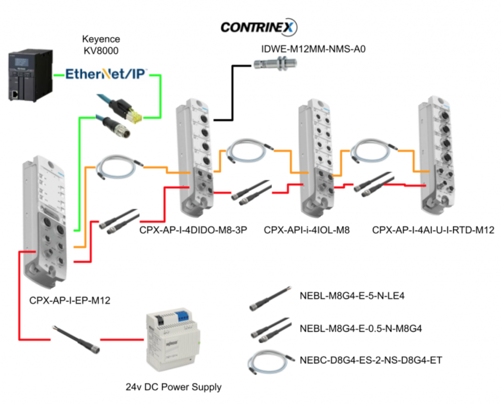
This time, I will set up an Ethernet/IP adapter on the FESTO CPX-AP-I-EP module and use the Keyence KV8000 as an Ethernet/IP scanner and also introduce the firmware update and IO-Link configuration tool for the Festo module. For Contrinex smart sensors, there are various detailed settings that cannot be used on default, so the easiest way is to use a tool to import the IODD file and configure the IO-Link sensor parameters.Let’s start!
IODD?
An IODD (IO-Link Device Description) is an XML format file provided by manufacturers for IO-Link compliant products. With the use of an IODD file, it becomes easier to configure the settings of IO-Link devices.
An IODD file typically consists of two main components: the manufacturer name-device name-date-IODD+IOLINK Version and the device image.
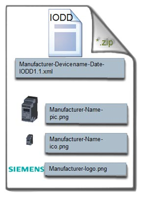
By importing the IODD File into an IO-Link Master (in this case, Festo), not only can the device settings and manufacturer information be easily accessed, but maintenance product lists and spare parts ordering also become simpler to manage.
IODD Checker?
IODD Checker allows checking not only the interchangeability of IODD files but also whether the IODD file itself conforms to the specifications. It is important to note that such testing is mandatory.
IODD Finder?
IODD Finder is a website within the IO-Link Community that allows end-users to search for and download IODD files.
COM1-3?
The IO-Link data transmission rate allows for the transmission of up to 32 bits per cycle between the device and the master. The standard has three specifications: COM1 at 4.8 kBit/s, COM2 at 38.4 kBit/s, and COM3 at 230.4 kBit/s.
Reference Link
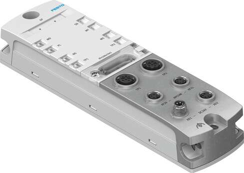
CPX-AP-I-EP-M12
This is the CPX-AP-I-EP-M12 that we will be using in this article. It is a flexible interface that can also support Ethernet/IP and Modbus TCP. While this article focuses on Ethernet/IP, we will also introduce Modbus TCP configuration in the next article.
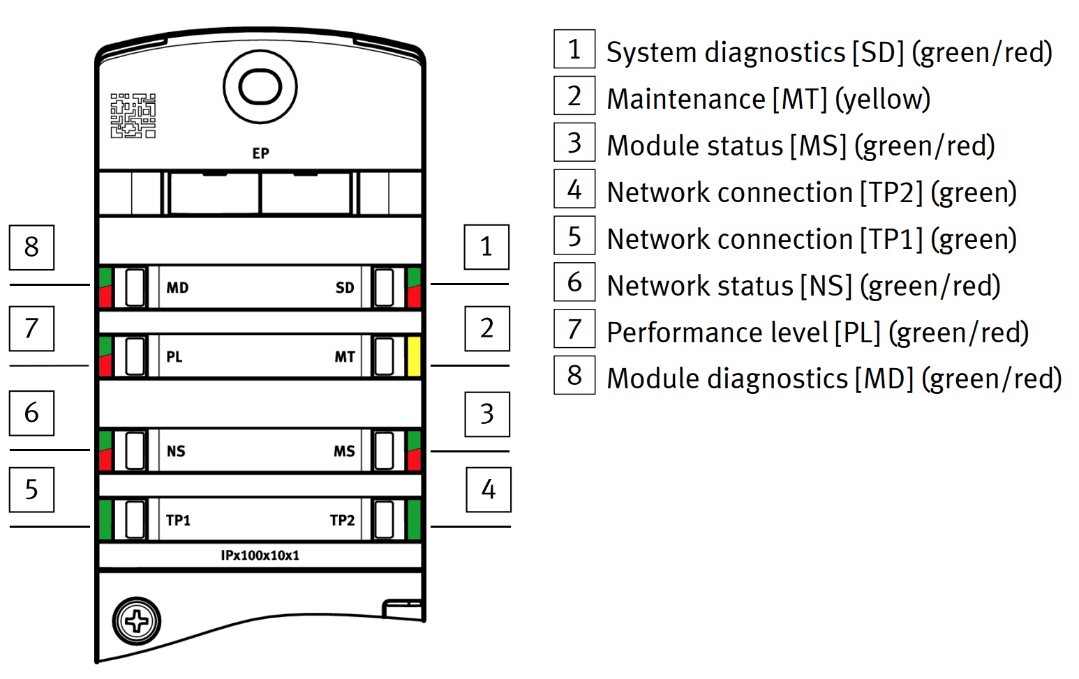
LED
These are the meanings of each LED on the module.
Rotary Switch
The module has three rotary switches that can be used to set the module’s IP address. Setting 0 allows the module to use DHCP, while settings 1-255 allow for fixed IP settings. If a setting of 1-255 is used, the leftmost rotary switch (x100) determines the range of the IP address, with a range of 300-555 for Ethernet/IP and 600-855 for Modbus TCP. For example, in this article, the IP address is set to 192.168.1.145, so the rotary switch settings would be x100=4, x10=4, and x1=5. A factory reset can be performed by setting the rotary switches to 900.
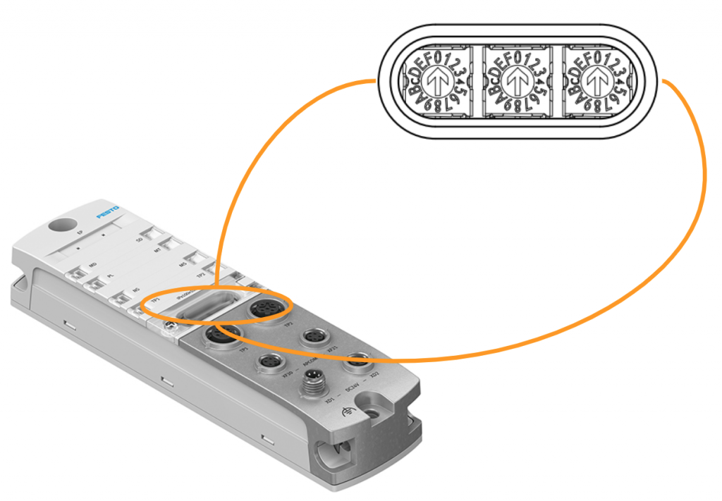
In this article, the Rotary Switch should be set to 645 as the IP address used is 192.168.1.145.

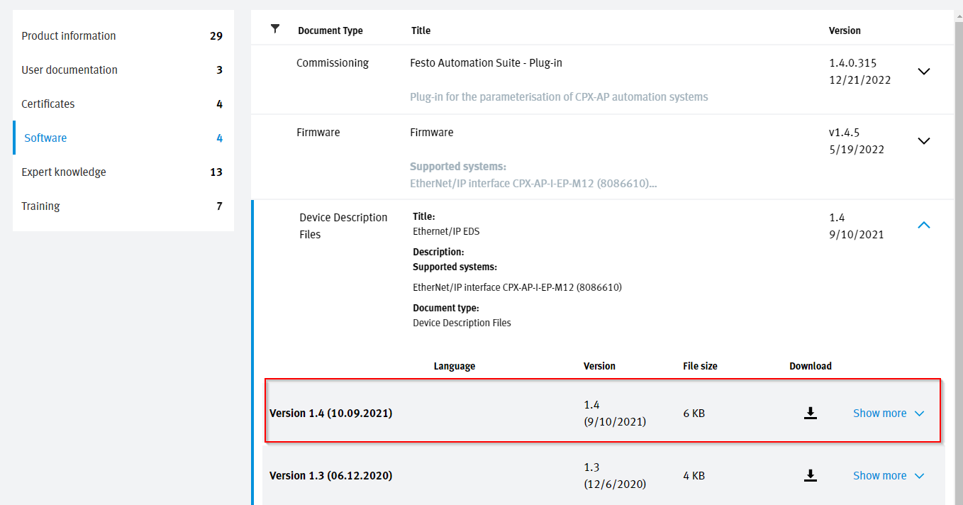
Download EDS File
Please download the EDS file from Festo’s website. Having the EDS file makes it easier to set up the Ethernet/IP network.
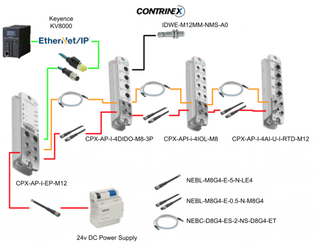
Configuration
This is the configuration for this article. The Ethernet/IP Scanner is Keyence’s KV8000.
Implementation1 Basic Configuration
First, power on the Festo CPX-AP-I-EP module.
Festo Side
Access the IP address you set via the Rotary Switch.
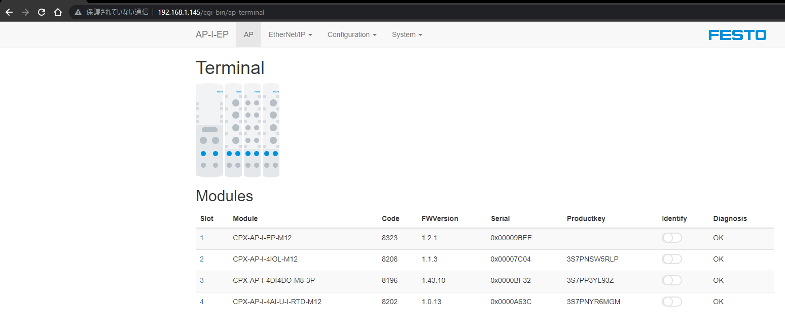
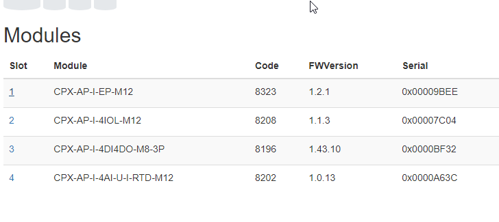
You can check detailed information for each module on the web server.
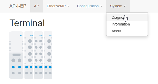
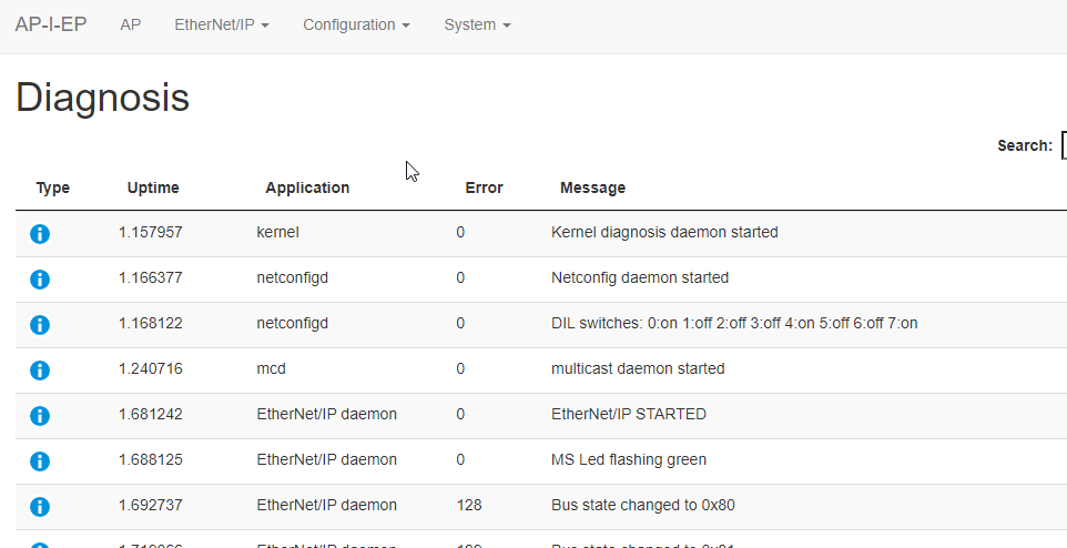
Diagnosis
Clicking on System > Diagnosis allows you to check the diagnostic information of the modules.
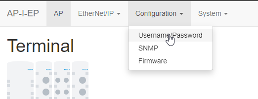
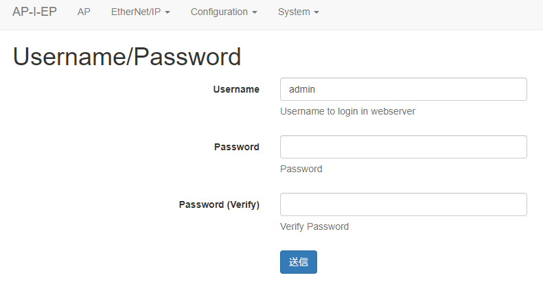
Username/Password
You can change the username and password from Configuration > Username/Password.
CPX-AP-I-4IOL-M12
Set IOLINK module’s Port 1 to IO-LINK mode.
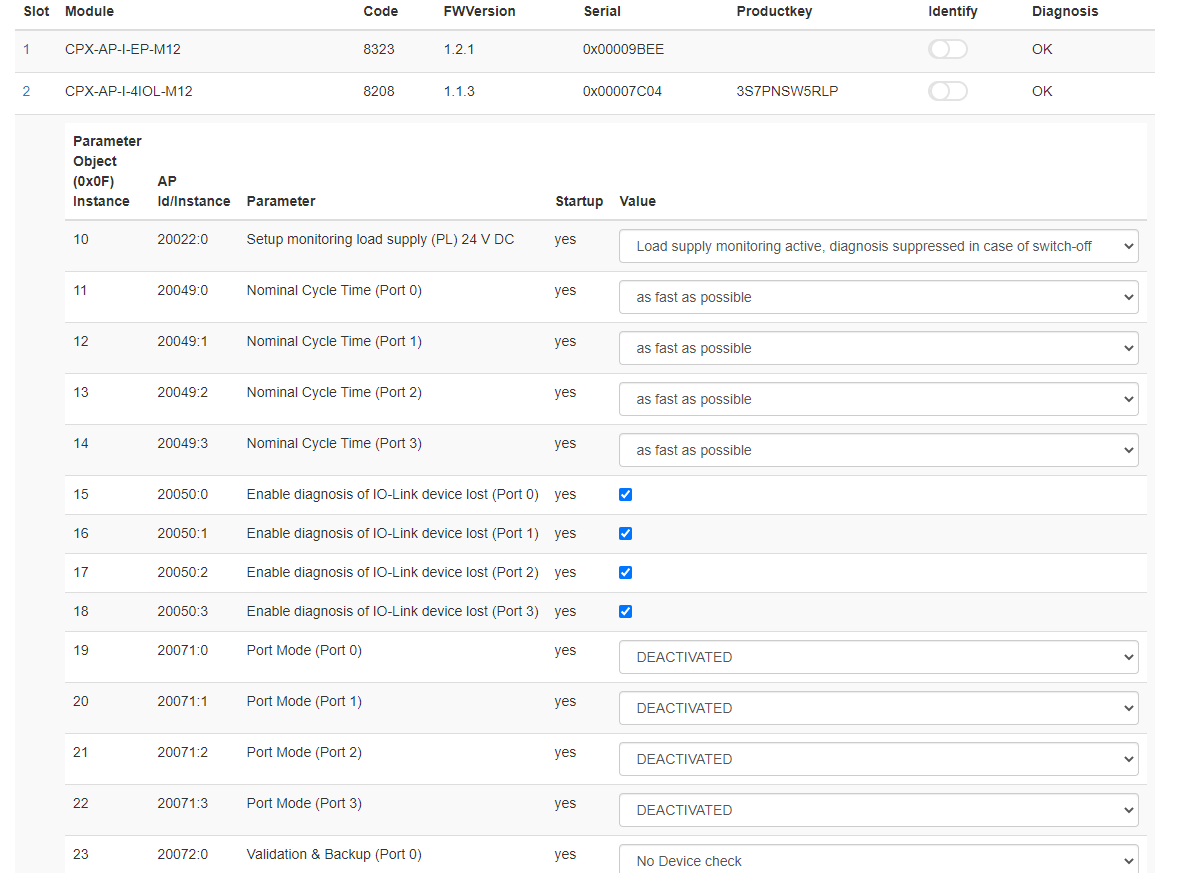
You just need to set IOL_AUTOSTART for the 20071:0.

Login is required.
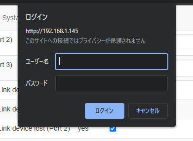
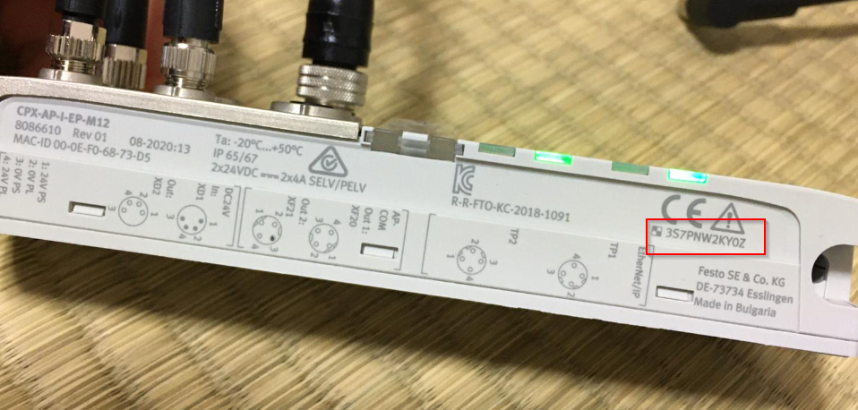
The username is “admin” and the password is the serial number printed on the module.
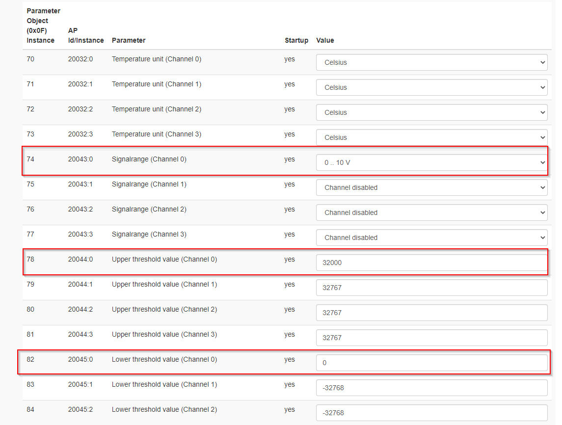
CPX-AP-I-AI-U-RTD-M12
Next, let’s configure channel 1 of the analog input module.
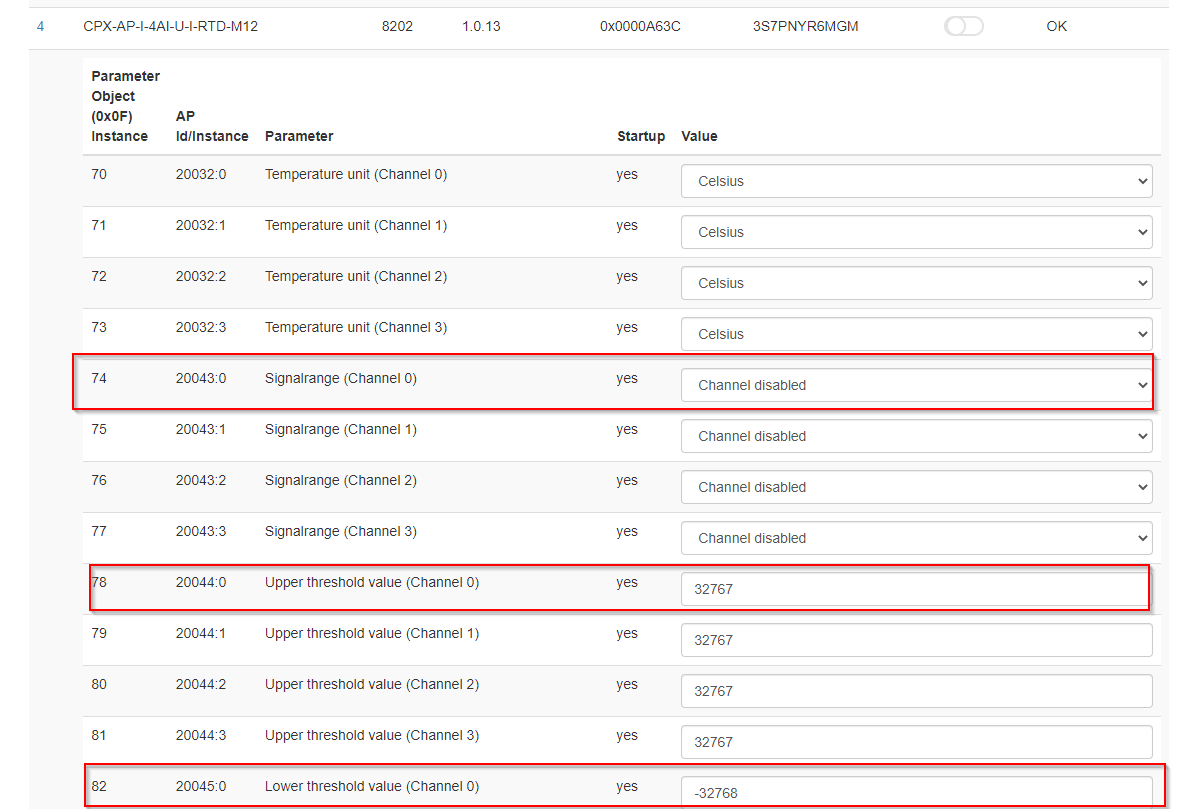
Set 20043:0 to measure 0-10V, and set 20044:0 and 20045:0 to 32000 and 0, respectively. This will scale 0-10V to 0-32000.
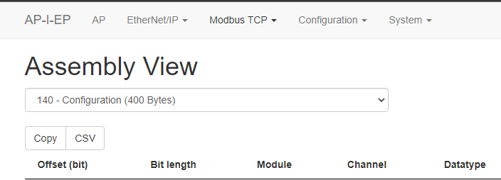
Assembly View
Click on Ethernet/IP > Assembly View to check the module’s assembly number and data exchange size.

Festo modules are very user-friendly and list offsets and sizes for all data related to the corresponding module.
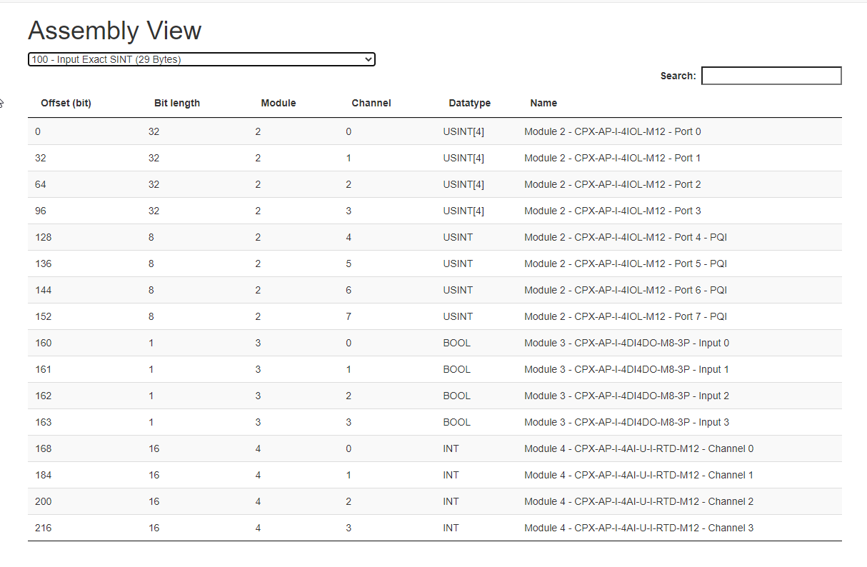
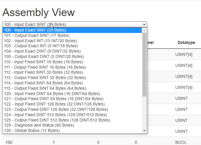
To view the desired Instance, select it from the drop-down list.
Keyence Side
Create New Project
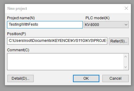
Launch KV STUDIO and create a new project by selecting File > New Project.

Enter the project name and click OK to confirm.
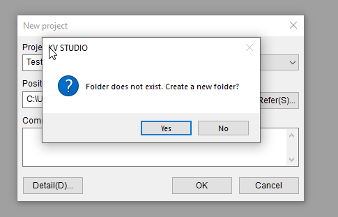
If the corresponding folder does not exist, create it.
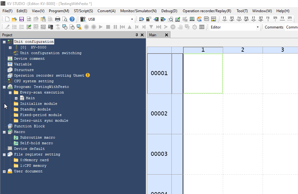
Done! A new project has been created.
Configure the EtherNet/IP Scanner
Click Unit Configuration > KV-8000 > Ethernet/IP to start setting up the Ethernet/IP network for KV8000.

Let’s proceed with Manual to manually build the network.

Register the EDS File
Click EDS File > Reg in KV Studio to register the EDS file.
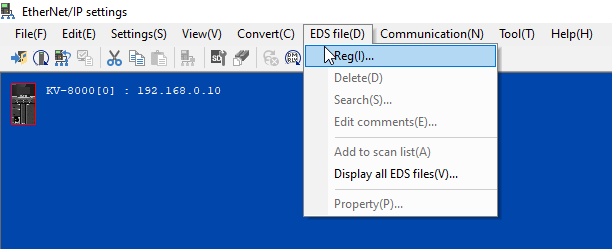
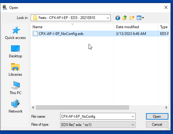
Click “Open EDS File” and select the EDS file that you downloaded from Festo’s web.
Done! The EDS File has been registered in KV Studio.
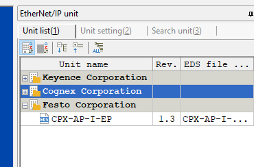
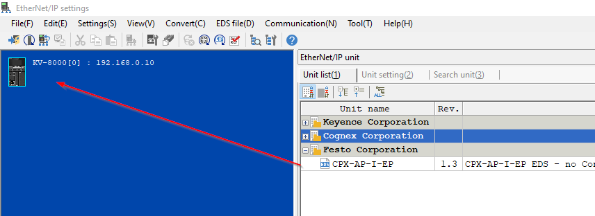
Configure the Festo Adapter
Next, we will add Festo’s CPX-AP-I-EP Ethernet/IP Adapter to the network. Simply drag the CPX-AP-I-EP from the right-hand Unit List to the KV-8000.
The Node Address and IP Address configuration screen will be displayed.
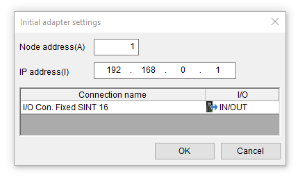
First, set the IP address to match the actual device and click OK. In this article, the IP address is 192.168.1.145.
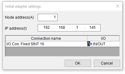
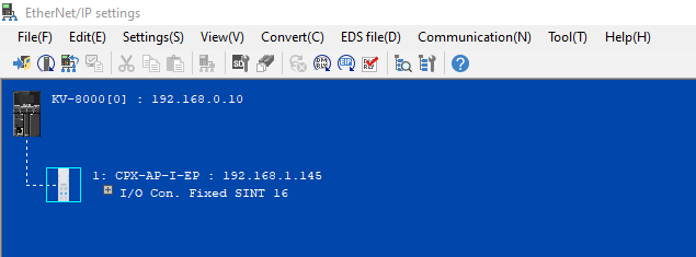
Done! Festo CPX-AP-I-EP has been added to the network.
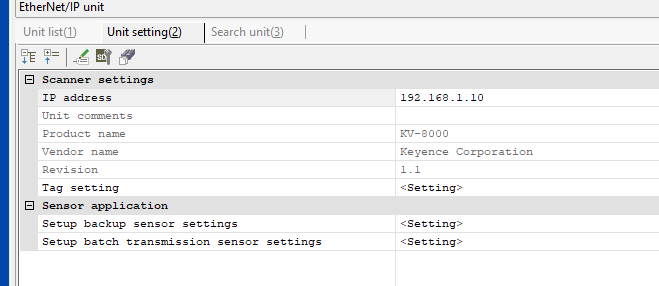
Change IP
Please set the KV-8000’s IP address to match the actual application.
Connection name
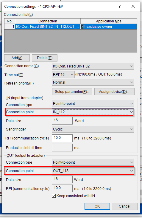
The Connection Name corresponds to the Festo module’s Assembly View. For example, I/O Con. Fixed SINT32 corresponds to Assembly 112, which is 32 bytes in size.
The connection point will also change automatically, so you don’t need to worry about it.
Doesn’t Work..?
It seems like there was a revision mismatch error from Festo, indicating that the EDS file version was not compatible From Wireshark.
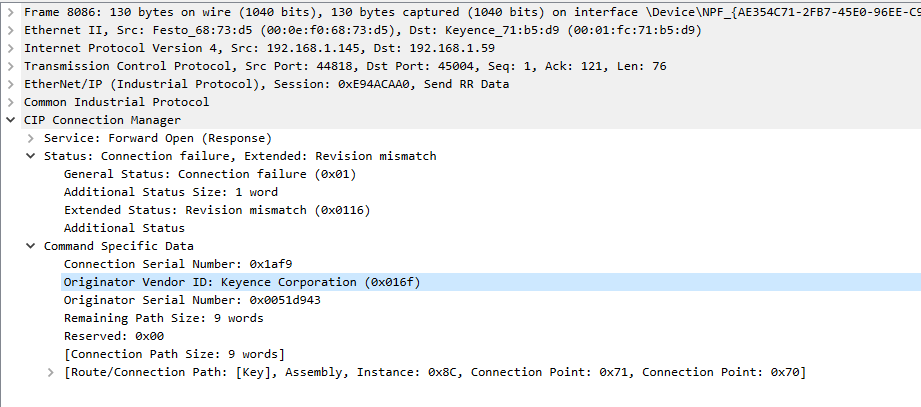
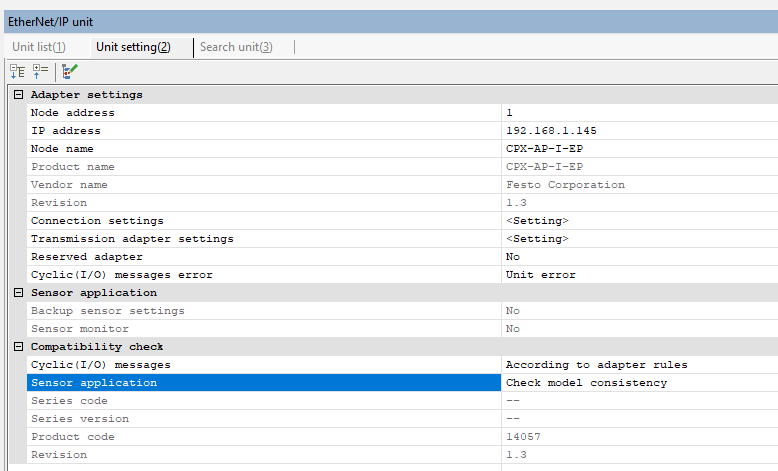
Okay, currently the EDS File for Festo devices in KV Studio is Revision 1.3.
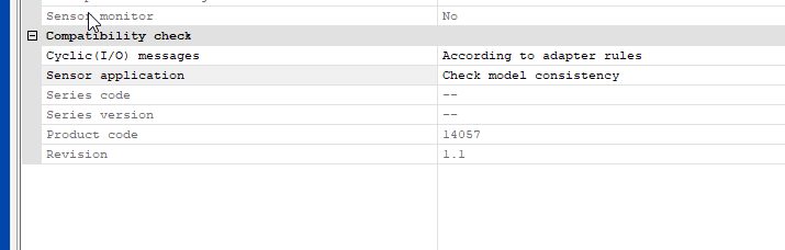
Access the Web Server of CPX-AP-I-EP-M12 and download the device’s EDS File by clicking on EtherNet/IP > EDS File.

And when you register the downloaded EDS file again in KV Studio, the revision was 1.1 instead of 1.3. That won’t work.
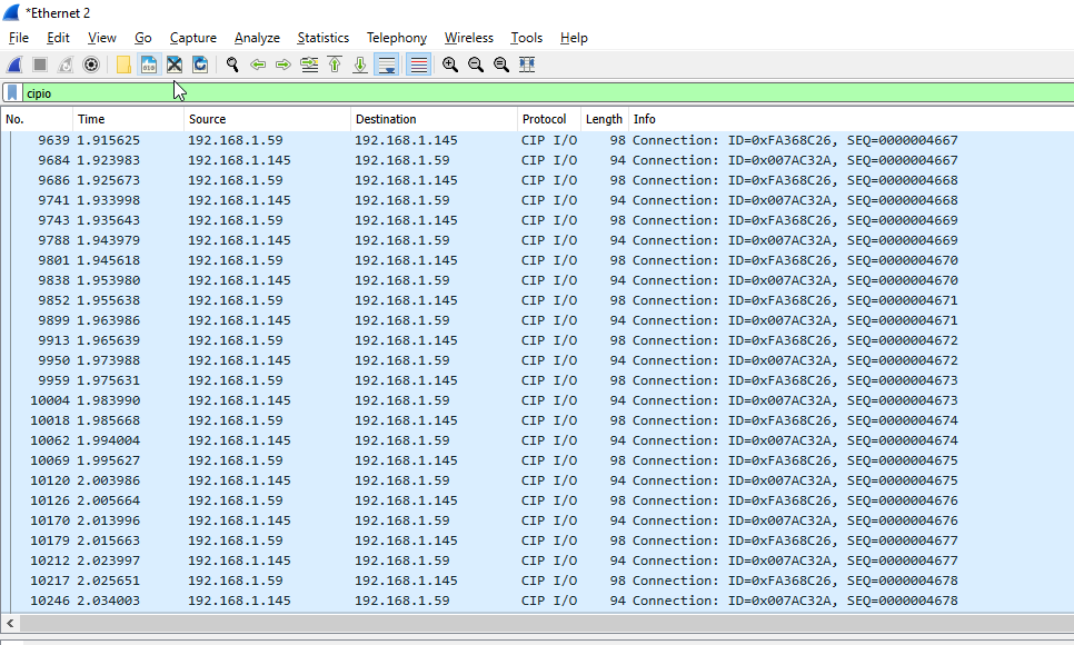
That means, after downloading this Ethernet/IP configuration with revision 1.1 to the CPU, it can be confirmed that CIP I/O Packages are flowing. This indicates a successful connection between the Festo device and Keyence KV8000.
Implementation-2 Firmware
But while I tried to configure the parameters of each module,these parameters will return back to default after a power restart.Let’s try to update the firmware of my modules to fix this problem.
Update Module Firmware
Please download the latest firmware for CPX-AP-I-EP-M12 from Festo HP.

Access the module’s web server and open Configuration > Firmware.
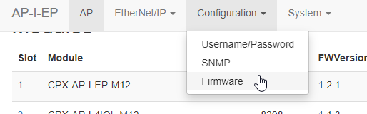
The Firmware upload screen is displayed. Click on the Browse button to select and upload the Firmware.
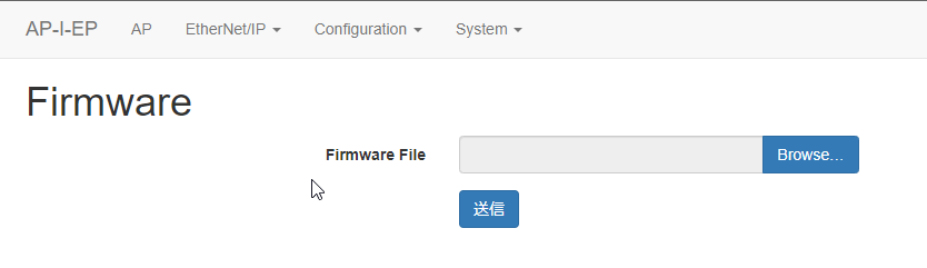
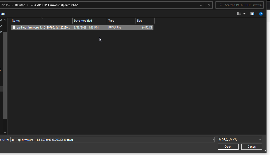
Select the firmware you downloaded earlier by clicking the Browse button and then selecting Open.
Click on the “Send” button to upload the firmware.

Please wait for a while.
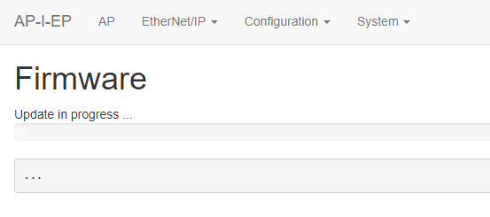
Done! You just need to power cycle the module.
When accessing the Web Server again, the Modbus TCP item has been added.
Configure and Store the Parameters
And most importantly, the Stored Parameter operation is now available in the Configuration menu.

Check “Store/Update current values” and click the “Send” button to save the parameters.
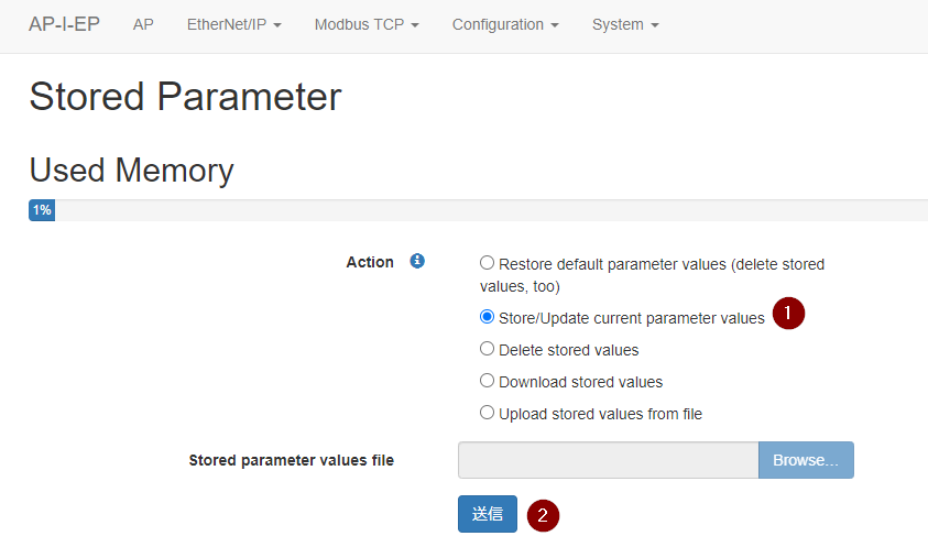
Done! With that, even if you power off the module and turn it back on again, the parameters will not be lost anymore!

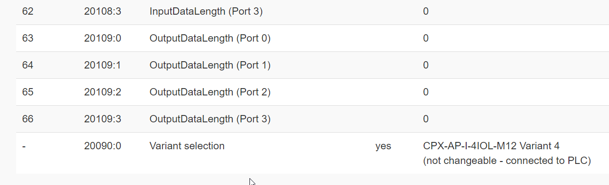
Implementation-3 IO-Link Variable Size
This time, I’m trying to change the Data Alias of the CPX-AP-4IOL-M12 module, but the message “Not Changeable -Connected to PLC” appears. This means that the module is connected to an upper-level scanner such as a PLC, so it cannot be changed.
Unplug the LAN cable from the KV8000. However, if it still cannot be changed, the message “Not Changeable – Stored Parameter active” appears, meaning that the stored parameters are active and preventing changes.

Click on Menu and then Configuration>Stored Parameter to access the Stored Parameter settings.
So in the previous screen, select the “Restored Default Parameter values (Delete stored)” checkbox and then click “Send”.
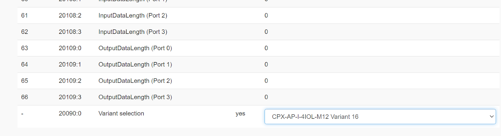
Great, now you can make the necessary changes!
Connection Settings in KV Studio
let’s change the Connection Name to “I/O Con.Fixed DINT128”. The Connection Point will automatically change to IN_122 and OUT_123.
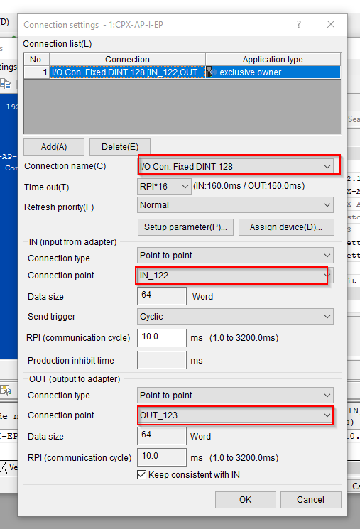
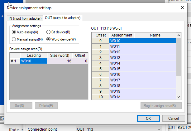
Next, click on “Assign Device”.

Go to the IN (Input from adapter) tab and set the device type for the assignment. Be careful not to overlap with existing programs.

OUT(output to adapter)のTabから振り分けのデバイス種類を設定します。既存プログラムにかぶらないように注意しましょう。
Implementation-4 Configure IO LINK
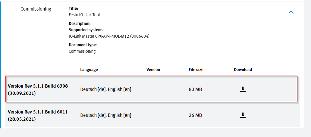
Download Configuration Tools
First, download the IO-Link Module Configuration Tool from Festo’s website.
https://www.festo.com/us/en/a/8086604/?q=io%20link~:festoSortOrderScored
Install Configuration Tools
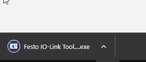
Double-click on the Configuration Tools installation file and follow the installation process.
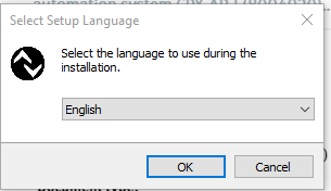
Choose English as the language and click OK to proceed.
Accept the agreements>next.

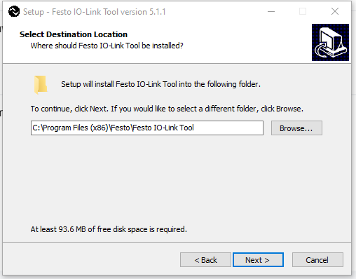
Configure the Installation path and Next.
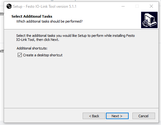
Create the shortcut to Desktop.
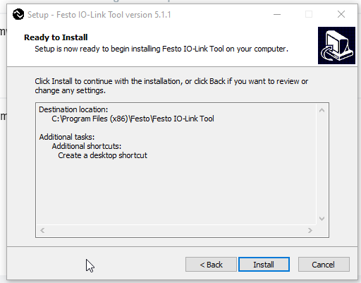
Start to Install.
Please wait for a while.
Done!
Launch SoftwareConfig
Launch it
Launch the Festo IO-Link Tool.
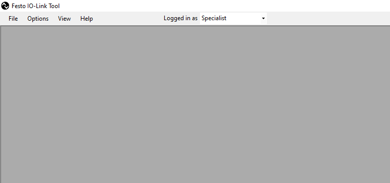
The screen of the Tool looks like this.
Search Master
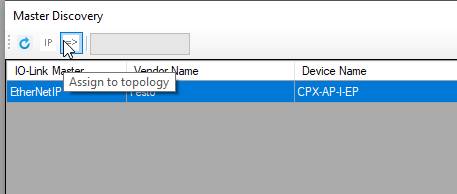
Click “Search Master” from the Topology section on the right to search for the IOLINK Master.

The IO LINK Master connected to the EtherNet/IP module CPX-AP-I-EP we are using in this article is visible.

Click “Assign to Topology” to add the device to the project.
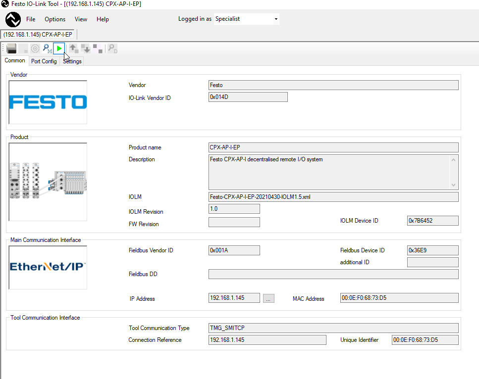
Done! The IO-LINK Master has been added to the Festo IO-Link-Tool.
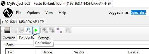
Go Online!
Click on the green “Play” button to connect to the device.

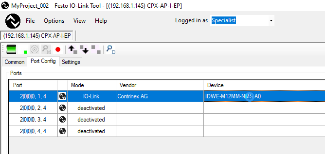
Click “read from master” to load the current IO-LINK Master settings.

Done! Now only Port1 is configured as an IO-LINK Port, and all other ports are disabled.

Download IODD
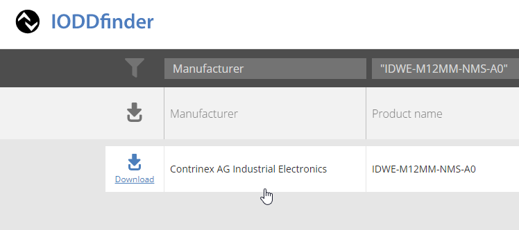
Next, download the IODD File of the Contrinex IDWE-M12MM-NMS-A0 smart sensor from the IODD Finder Web.
https://ioddfinder.io-link.com/#/
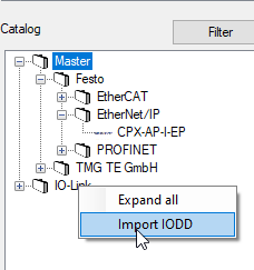
Import IODD
You can import the IODD File from the Catalog to the right of Festo Configuration Tools. Right click > Import IODD.
Click the … button and open the IODD File you just downloaded.

Click the Import button.
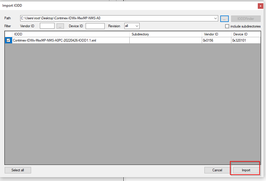
Contrinex smart sensors have been added to the Catalog.

Insert
Next, import the IDWE-M12MM-NMS-A0 used this time into Port0. Select IDWE-M12MM-NMS-A0 from Catalog, and just plug it into Port1.
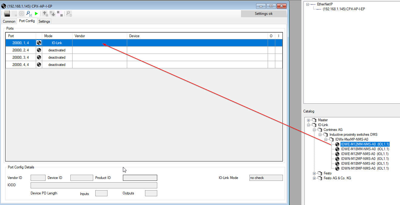
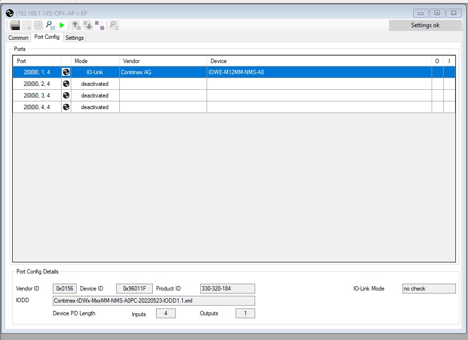
Done! Port1 is set.
Download Configuration
Download the Configuration to Festo’s IO-LINK Master.
Disconnect with plc
However, if the Festo CPX-AP-I-EP module is connected to a host system such as a PLC, Configuration Download cannot be performed.
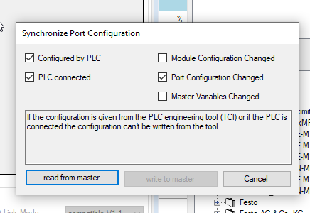
All right! I was able to download it.
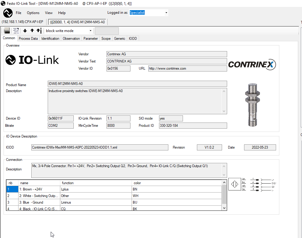
When I went online, I was able to view Contrinex’s sensor information and parameters!
Upload
Upload the Contrinex sensor parameters and back them up separately.

Configure your IO Link Devices
Reset
Reset the device by executing Device Reset or Factory Reset from System Commands.

ALR Setting
Here are the Contrinex ALR1/ALR2/ALR3 alarm settings.
ALR1 is Distance, that is, a function that measures distance. Threshold is 80.00, i.e. ALR1=True when the measured value exceeds 80.
ALR3 is a measurement of temperature, above 30.00 ALR3=True.

MHM
MHM is the measurement rms value setting.
MHM Source is the type to measure, 0=Distance.
MHM Range Start=0, MHM Range 110.0 means the measured value is 0-110.

Process Data
Click the Process Data Tab to Monitor the 4 Bytes Input/ 1 Bytes Output status of the Contrinex smart sensor.

Implementation- Program in KV−Studio
Create a program in KV Studio to control the module connected to Festo’s CPX-AP-I-EP-M12.
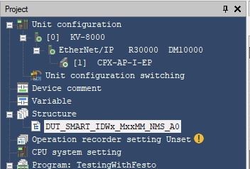
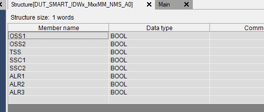
DUT
Create a DUT_SMART_IDWx_MxxMM_NMS_A0 Structure Type.
Contrinex sensor IO LINK data Byte0 data is decomposed into BOOL.
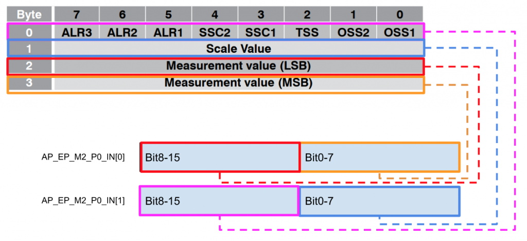
Process Data Mapping
Note that the Contrinex sensor byte order is different from the Keyence CPU, so distribute 4 bytes of IO LINK data to the KV8000 as shown below.
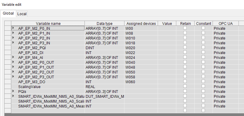
Global Variables
Define the input/output data of each module connected from W00 to CPX-AP-I-EP-M12 in the Global variable.
Program
Here is a sample program that I made.
| //Digital Output AP_EP_M3_DO.0:=AP_EP_M3_DI.0; AP_EP_M3_DO.1:=AP_EP_M3_DI.1; AP_EP_M3_DO.2:=AP_EP_M3_DI.2; AP_EP_M3_DO.3:=AP_EP_M3_DI.3; //Analog Input ScalingValue:=(INT_TO_REAL(AP_EP_M4_AI[0])/32000.0)*10.0; // PQIs[0]:=AP_EP_M2_PQI & 16#000F; PQIs[1]:=AP_EP_M2_PQI & 16#00F0; PQIs[2]:=AP_EP_M2_PQI & 16#0F00; PQIs[3]:=AP_EP_M2_PQI & 16#F000; //IO Link Sensor SMART_IDWx_MxxMM_NMS_A0 //Sensor Status SMART_IDWx_MxxMM_NMS_A0_Status.OSS1:=AP_EP_M2_P0_IN[1].8; SMART_IDWx_MxxMM_NMS_A0_Status.OSS2:=AP_EP_M2_P0_IN[1].9; SMART_IDWx_MxxMM_NMS_A0_Status.TSS:=AP_EP_M2_P0_IN[1].10; SMART_IDWx_MxxMM_NMS_A0_Status.SSC1:=AP_EP_M2_P0_IN[1].11; SMART_IDWx_MxxMM_NMS_A0_Status.SSC2:=AP_EP_M2_P0_IN[1].12; SMART_IDWx_MxxMM_NMS_A0_Status.ALR1:=AP_EP_M2_P0_IN[1].13; SMART_IDWx_MxxMM_NMS_A0_Status.ALR2:=AP_EP_M2_P0_IN[1].14; SMART_IDWx_MxxMM_NMS_A0_Status.ALR3:=AP_EP_M2_P0_IN[1].15; //Scaling Value SMART_IDWx_MxxMM_NMS_A0_ScalingValue:=AP_EP_M2_P0_IN[1] & 16#00FF; //Measure Value SMART_IDWx_MxxMM_NMS_A0_MeasureValue:=(INT_TO_REAL(SWAP(AP_EP_M2_P0_IN[0]))/16383.0)*110.0; //Enable,Disable the Sensor,0=Enable AP_EP_M2_P0_OUT[0].0:=AP_EP_M3_DI.2; |
Result
You downloaded the project to the KV8000 and can receive the data from the Festo CPX-AP-I-EP-M12!

Analog input values and Contrinex smart sensors were also collected.

The current value of the IOLINK Sensor is consistent with Festo’s IO LINK.
Scope
Finally, we will introduce useful functions of the Festo IO-LINK Tool. It’s a Scope function.
Open the Scope tab.

Right-click > Configuariton.
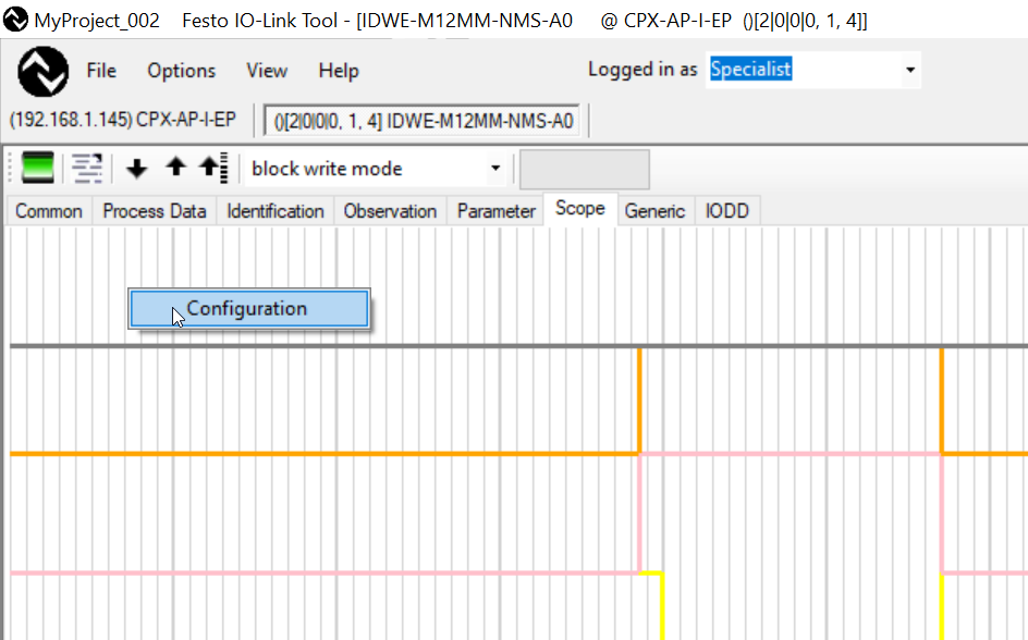
You can check the Variable you want to monitor in the Visible area, but also set the Color.

Done!

You can check the actual status of the module from this video.