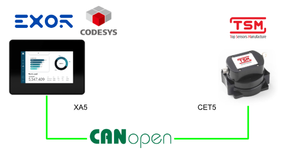
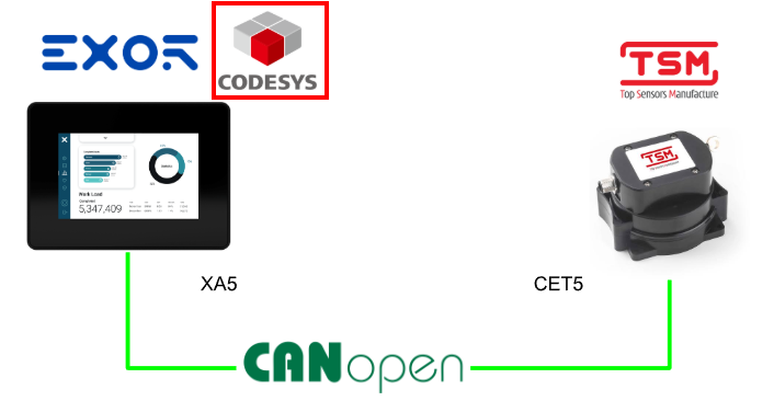
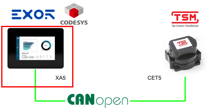
In this article, we will connect TSM’s CET5 sensor to EXOR’s in-vehicle HMI XA5 and perform CANopen communication on the CODESYS Runtime.
Furthermore, we will make it possible to check the acquired data from the JMobile screen.
Let’s enjoy FA.
CET?
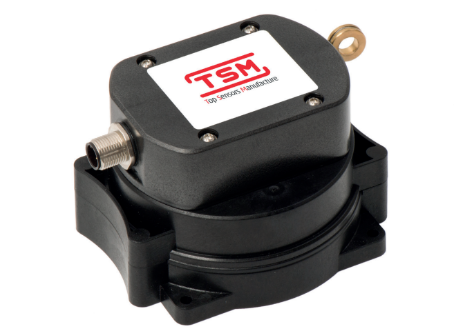
The CET5 is a robust, high-performance wire-actuated displacement sensor with CANopen output, possessing the high quality and durability required for industrial applications. Due to its excellent repeatability, high IP protection rating, shock and vibration resistance, and electromagnetic noise immunity, it is suitable for mobile hydraulic equipment such as agricultural vehicles, earthmoving machinery, construction machinery, articulated arm cranes, and aerial work platforms.
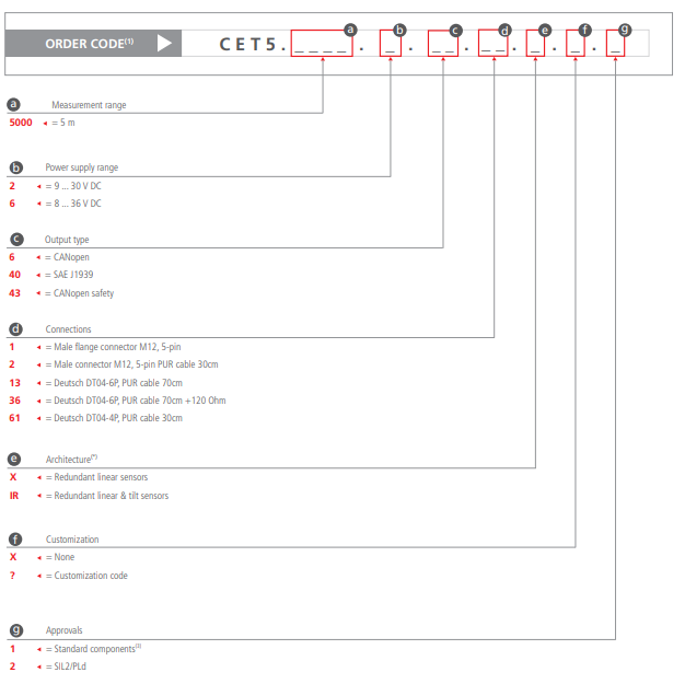
The order code for the CET5 series is configured by combining measurement range, power supply voltage range, output method, connection specifications, sensor configuration, customization availability, and certification specifications. By specifying each code, you can select product specifications according to your application. For example, you can clearly specify specifications such as measurement range, CANopen communication, Deutsch connector, redundant sensor configuration, and SIL2/PLd support on the order code.
Operating Principle
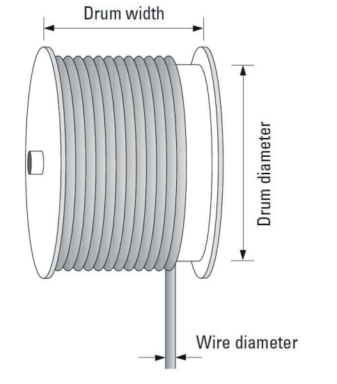
The wire-actuated displacement sensor has an internally supported drum supported by bearings, around which a wire rope is wound.
When the wire rope is pulled out, the drum rotates in conjunction with its movement. The linear movement amount of the wire rope is converted into the rotation angle of the drum.
By detecting the rotation angle of this drum, the pull-out amount of the wire, i.e., the linear displacement amount, is measured.
Note that using the sensor beyond the maximum wire pull-out length may damage the wire and internal mechanism. When using, always use within the measurement range defined in the specifications.
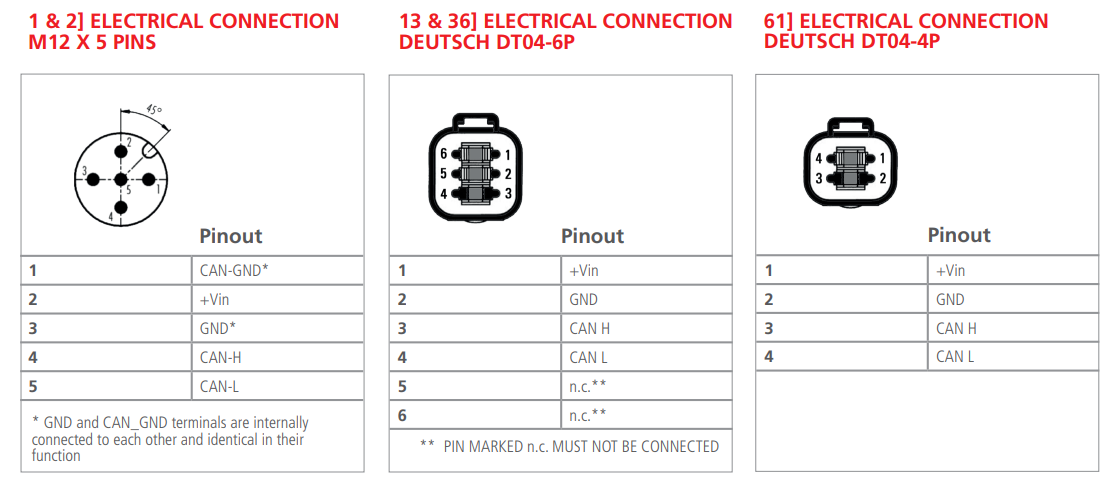
Terminal Block
CANOPEN
CANopen is an open and non-proprietary standard communication protocol based on CAL (CAN Application Layer), which is the application layer of the Controller Area Network (CAN). It is a communication standard located at the 7th layer of the ISO/OSI reference model, developed and internationally standardized by the CAN in Automation (CiA) user group, and is still maintained today.
The CET sensor, as a CANopen device, meets the requirements of device specifications based on CiA DS301. It also partially supports CiA DS406, which is a device profile for encoders, and CiA DS410, which is a device profile for inclinometers.
Communication Objects
CANopen communication is performed via CAN messages. A CAN message is a command sent to or from a device, and is exchanged on the CAN bus in the form of a network packet.
Each CAN message consists of the following elements:
- Identifier (CAN message ID)
- Control bits
- 0 to 8 bytes of data
CAN messages are sometimes called Communication Objects, or COB for short. Also, the CAN message ID is called COB-ID.

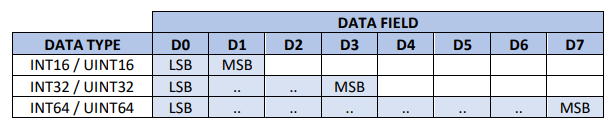
All numeric data types are stored in the data field in little-endian format. Therefore, the LSB (Least Significant Byte) is placed at the lowest data index, and the MSB (Most Significant Byte) is placed at the highest data index. An example placement is shown in the table below.
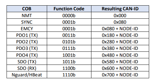
The 11-bit identifier (COB-ID) consists of a 4-bit function code and a 7-bit Node ID. The function code indicates the type and priority of the communication object, and the Node ID is used to identify CANopen devices existing on the same network. This mechanism allows each communication object to be properly identified and managed within the CANopen network.

This mechanism allows for peer-to-peer communication between one CANopen master device and up to 127 NMT slave CANopen devices. The CET supports the communication objects detailed in the chapters below.
- Network Management Object (NMT)
- Synchronization Object (SYNC)
- Emergency Object (EMCY)
- Process Data Object (PDO)
- Service Data Object (SDO)
- Node Guarding / Heartbeat
PDO
Process Data Objects (PDOs) are mapped to a single CAN frame using a data field of up to 8 bytes to transmit application objects.
Transfer via PDO takes place in real time without additional protocol overhead. Each PDO is assigned a unique identifier and is transmitted from only one node. However, that PDO can be received by multiple nodes. This is called producer/consumer communication.
PDOs are defined by communication parameters and mapping parameters. Communication parameters indicate the communication functions and conditions of the PDO, and mapping parameters indicate the data content contained in that PDO.
Communication parameters and application parameters that determine the operation of a CANopen device are managed in a standardized list called an Object Dictionary.
In the object dictionary, a unique 24-bit address is assigned to all data exchanged between the communication part, such as the CANopen protocol stack, and the device’s application software part.
This 24-bit address consists of the following two:
- 16-bit Index
- 8-bit SubIndex
Each entry in the CANopen object dictionary can be read using CANopen communication services.
TPDO1 – Linear sensors output
Depending on the device version, different static mappings are provided for TPDO1. Specifically, there are mappings for the CET5 model and mappings for the CET7, CET12, and CET20 models, respectively.
TSM16 mapping: Valid for CET5:

TSM32 mapping: Valid for CET7, CET12, CET20:

Position 1 and Position 2 indicate the length measurements obtained by the two linear sensors. The data format depends on the mapping method.
- TSM16 mapping: INT16
- TSM32 mapping: INT32
The endian format is little-endian, and the resolution is 0.1 mm.
- Position 1 is represented as a direct value (0 to FS).
- Position 2 is represented as a complement value (0 to -FS).
For TSM16 mapping, if the length measurement is 1000.0 mm:
D0 = 0x10, D1 = 0x27
→ Position 1 = 0x2710 = 10000d
Since the resolution is 0.1 mm,
10000 × 0.1 mm = 1000.0 mm
On the other hand, Position 2 is represented as a complement value as follows:
D2 = 0xF0, D3 = 0xD8
→ Position 2 = 0xD8F0 = -10000d
In other words, -10000 × 0.1 mm = -1000.0 mm
TPDO2 – Inclinometers output
This mapping function is available for all CET models with built-in inclinometers.

Angle 1 and Angle 2 indicate the angle measurements obtained by the two inclinometers, the data format is INT16, and the endian format is little-endian. The resolution is 0.1°.
Angle 1 is represented as the angle in the clockwise direction (0 to 3599).
Angle 2 is represented as the angle in the counterclockwise direction (3599 to 0).
Here, since the value is represented in 0.1° units, for example, 900 means 90.0°.
If the angle measurement is 90.0°:
D0 = 0x84, D1 = 0x03
→ Angle 1 = 0x0384 = 900d
Since the resolution is 0.1°,
900 × 0.1° = 90.0°.
On the other hand, Angle 2 is represented as a value in the counterclockwise direction as follows:
D2 = 0x8C, D3 = 0x0A
→ Angle 2 = 0x0A8C = 2700d
In other words, 2700 × 0.1° = 270.0°.
SDO
Service Data Objects (SDO) are used to read from and write to entries in the object dictionary. The SDO transfer protocol supports object transfers of arbitrary size, and transmits and receives data divided into multiple segments as necessary. Each segment contains control information and user data, and the receiving side returns a confirmation response for each segment or segment block. If the transfer fails, an abort message is sent.
The CET also includes an SDO server function as a standard setting. In SDO communication, you can read and write data to the object dictionary, and the CET supports both expedited transfer and normal transfer (segmented transfer). Expedited transfer is a method of transmitting and receiving small amounts of data up to 4 bytes in a single CAN frame.
Transmission
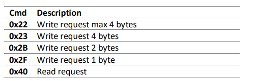
To initiate an expedited transfer, the master sends the following message:

Cmd is the command specifier indicating the request type.
Index and Sub-Id indicate the address of the object dictionary entry to be accessed. Data stores the write value in the case of a write command.
Reception
The sensor responds with the following message:

Ans is the response specifier indicating the response type.
Index and Sub-Id indicate the address of the object dictionary entry that was accessed. Data stores the read value in the case of a read command.
If the transfer fails, an abort code is stored in the Data field.
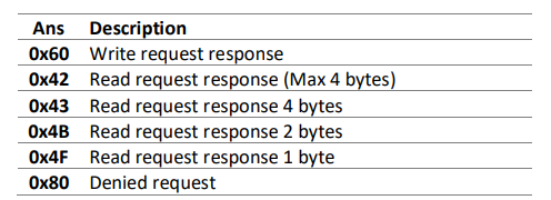
The 0x80 abort message indicates that the transfer did not complete successfully.
The reason for this is one of the reasons listed in the abort code table in section 8.3.
Node ID
Each device on the CANopen network is uniquely identified by its own Node-ID. The Node-ID is set in the range of 1 to 127 and must be set so that it does not overlap within the same network. To change the Node-ID, send the SDO command shown below.
(Default ID=4)

Store parameters
All parameters in the object dictionary can be saved to a dedicated area provided in the internal non-volatile memory. This storage area is protected by checksum calculation and mirrored backup. This ensures that data loss is prevented even if an unexpected power failure occurs during the saving process.
However, due to the internal structure of the microcontroller, there is a limit to the number of times parameters can be written, which is up to 10,000 times.

Store default parameters
By using this SDO, all parameters in the object dictionary saved in the non-volatile memory can be restored to factory default values. Note that a device reset is required to complete the restoration process.

set/reset customer INCLINOMETER ZERO point (Preset value)
With this command, the angle measurement value can be corrected to an arbitrary preset value. If you set 0 as the preset value, you can register the current sensor position as the zero point of the inclination angle. In the case of a redundant sensor configuration, this setting applies to both of the two angle outputs.

- Format: UINT16
- Resolution: Resolution set by another command.
- Range: 0 to 65535
PRESET value | Operation |
|---|---|
0 | Set zero point |
Non-zero | Set preset point |
FB
Next, I will introduce the FB used in this article.
SDO_WRITE_DATA (FB)
This function block is used to write data to a specific object in the device’s object dictionary. When data is written without error, CONFIRM becomes TRUE.
DATA must be specified in little-endian byte order. If an error occurs, ERROR will be a non-zero value.
If an SDO abort occurs, ERROR is set to CANOPEN_KERNEL_ERROR.CANOPEN_KERNEL_OTHER_ERROR, and the corresponding abort code defined in CiA 301 is stored in ERRORINFO in little-endian format.
VAR_INPUT
Name | Type | Description |
|---|---|---|
NETWORK | USINT | Specifies the CAN network number on which the function block operates. This is different from the network number on the CANbus configurator. The NETWORK of CiA405 is calculated as NETID + 1. Example: 1 = CAN0, 2 = CAN1, 3 = CAN2 |
ENABLE | BOOL | Activates the function block on the rising edge. Interrupts processing on the falling edge. |
TIMEOUT | UDINT | Specifies the timeout time in ms. 0 means no timeout. |
DEVICE | DEVICE | Specifies the Node-ID of the destination device. 0 means the local device, i.e., CANopen Manager. |
CHANNEL | USINT | Specifies the SDO channel to use. 0 uses any free channel, 1..n specifies a specific channel. |
INDEX | WORD | Specifies the Index of the object to be written to. |
SUBINDEX | BYTE | Specifies the SubIndex of the object to be written to. |
MODE | SDO_MODE | Specifies the SDO mode to use. Usually use SDO_MODE.AUTO. |
DATA | POINTER TO BYTE | Specifies the pointer to the data to be written. The data must be specified in little-endian byte order. |
DATALENGTH | UDINT | Specifies the length of the data to be written in bytes. |
CONFIRM | BOOL | TRUE indicates that the function block has completed normally without errors. |
ERROR | CANOPEN_KERNEL_ERROR | Indicates the content of the error that occurred during processing. Refer to CANOPEN_KERNEL_ERROR for details. |
VAR_OUTPUT
Name | Type | Description |
|---|---|---|
CONFIRM | BOOL | TRUE indicates that the SDO write processing has completed normally without errors. |
ERROR | CANOPEN_KERNEL_ERROR | Indicates the error code that occurred. Refer to CANOPEN_KERNEL_ERROR for details. |
ERRORINFO | SDO_ERROR | Indicates detailed information when an SDO abort occurs. If ERROR is CANOPEN_KERNEL_ERROR.CANOPEN_KERNEL_OTHER_ERROR, the abort code defined in CiA 301 is stored in little-endian format. |
SDO_READ
SDO_READ function block is used to read data from a specified object in the CANopen device’s object dictionary. When reading is completed normally, CONFIRM becomes TRUE, and the read data is stored in DATA in little-endian byte order. When an error occurs, ERROR will be non-zero. If an SDO abort occurs, ERROR is set to CANOPEN_KERNEL_ERROR.CANOPEN_KERNEL_OTHER_ERROR, and the abort code defined in CiA 301 is stored in ERRORINFO in little-endian format.
VAR_INPUT
Name | Type | Description |
|---|---|---|
NETWORK | USINT | Specifies the CAN network number on which the function block operates. This is different from the network number on the CANbus configurator. The NETWORK of CiA405 is calculated as NETID + 1. Example: 1 = CAN0, 2 = CAN1, 3 = CAN2 |
ENABLE | BOOL | Activates the function block on the rising edge. Interrupts processing on the falling edge. |
TIMEOUT | UDINT | Specifies the timeout time in ms. 0 means no timeout. |
DEVICE | DEVICE | Specifies the Node-ID of the destination device. 0 means the local device, i.e., CANopen Manager. |
CHANNEL | USINT | Specifies the SDO channel to use. 0 uses any free channel, 1..n specifies a specific channel. |
INDEX | WORD | Specifies the Index of the object to be read. |
SUBINDEX | BYTE | Specifies the SubIndex of the object to be read. |
MODE | SDO_MODE | Specifies the SDO mode to use. Usually use SDO_MODE.AUTO. |
DATA | POINTER TO BYTE | Specifies the pointer to the memory area where the read data will be written. The data is stored in the CANopen byte order, i.e., little-endian format. |
Implementation
Then, let’s actually create the project.
Codesys side
First, build from the Codesys side of the EXOR XA5.
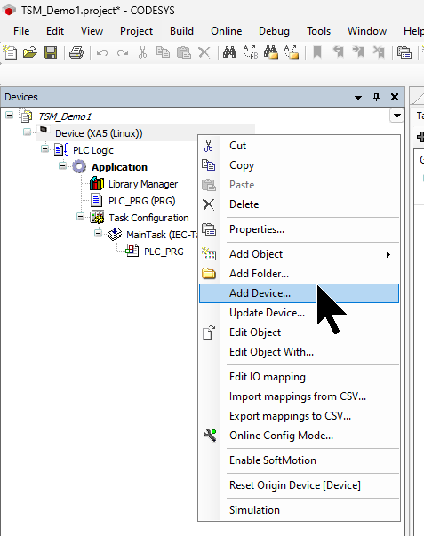
Adding CAN master
Select Device from the Codesys project → right-click → Add Device.
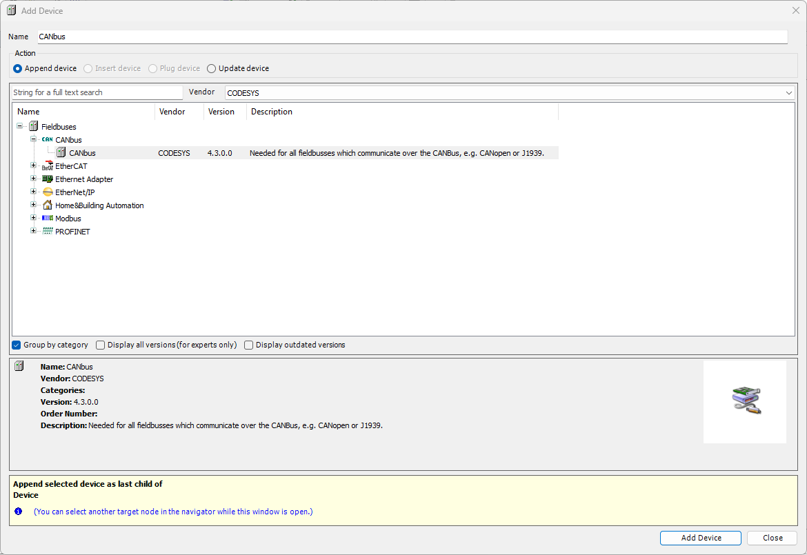
Add Fieldbus → CANBus.
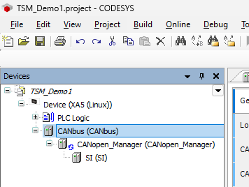
Now CANBus has been added.
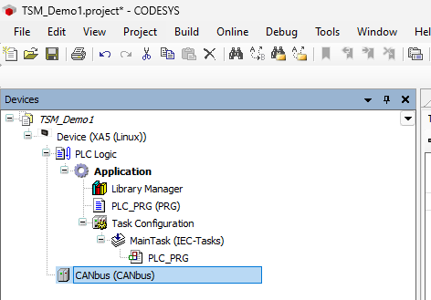
Adding CAN manager
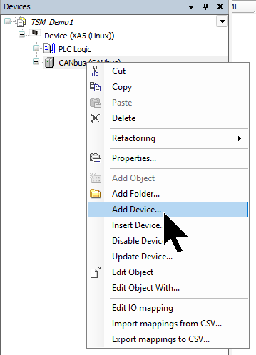
Next, to add CANOpen Manager, right-click on the CANBus added earlier → Add Device.
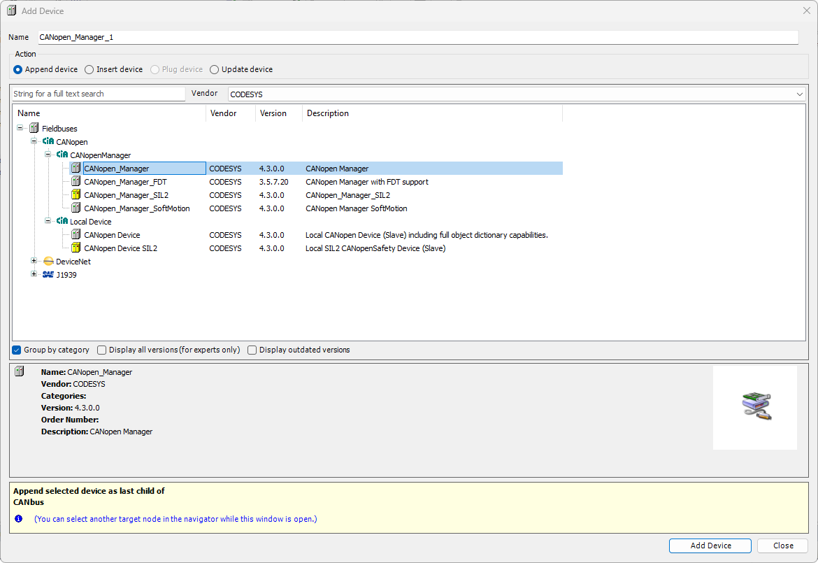
Let’s add CANopen → CANopen Manager → CANopen Manager.
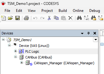
Now the CANOPEN Master has been added.
Installing EDS file
Next, to install the EDS FILE for the TSM CET5 sensor used in this article, click Tools → Device Repository.
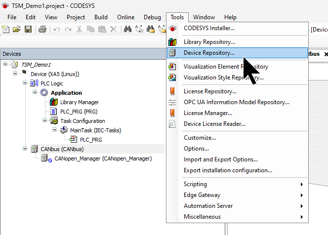
Click the Install button.
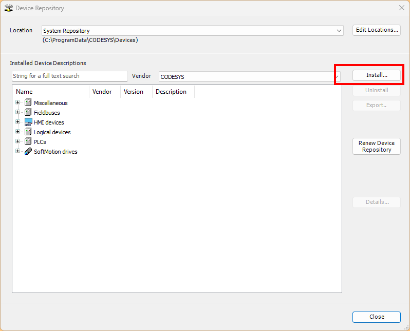
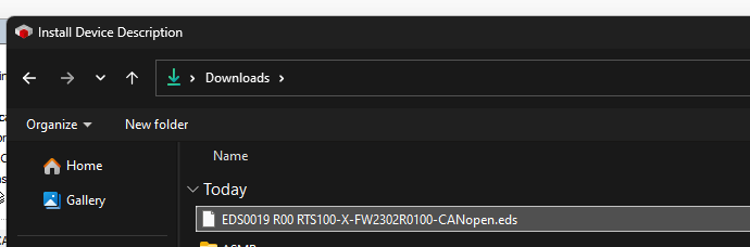
Select the CET5 EDS FILE.
Now the CET5 EDS FILE is registered.
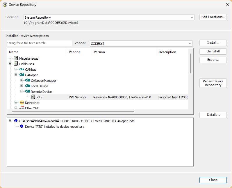
Adding CET5
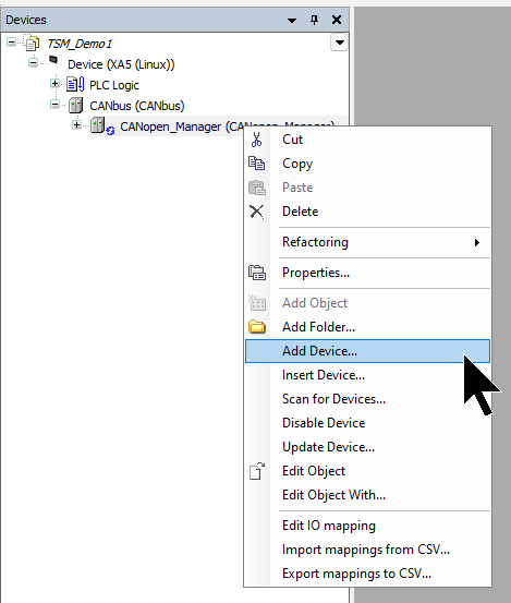
Next, to add the TSM CET5 sensor to the CAN OPEN network, right-click on CANopen Manager → Add Device.
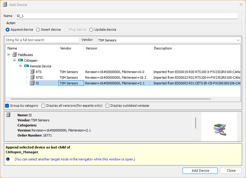
Select and add the TSM CET5 sensor (SI) used in this article.
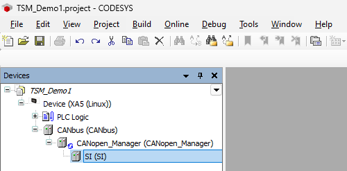
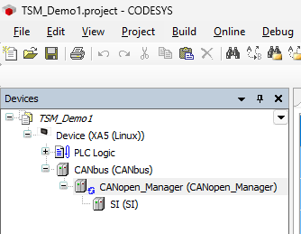
The TSM CET5 sensor has been added to the CAN OPEN network.
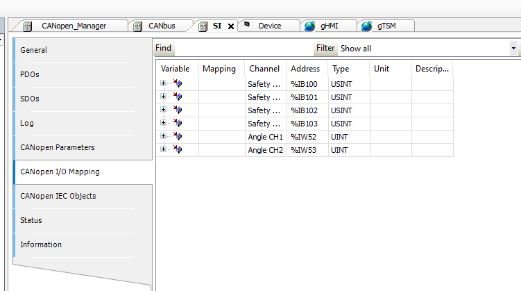
From “Address” in the CANOPEN I/O Mapping Tab, you can see that the absolute address occupied by this Sensor starts at %IB100. That address will be used when defining variables in the GVL later.
CAN bus settings
Next, set the CANbus communication settings, etc.
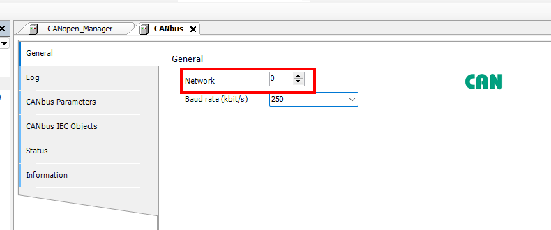
Set General → Network to 0. We will use CAN BUS1 of the XA5, so if you use CAN BUS2, set the Network number = 1. Also, set the Baud Rate according to your application.
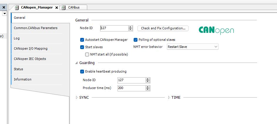
CAN Open Manager settings
Now set up the CAN Open Manager.
Just setting General → Node-ID is fine.
CET5 sensor settings
Finally, it is the setting for CET5.
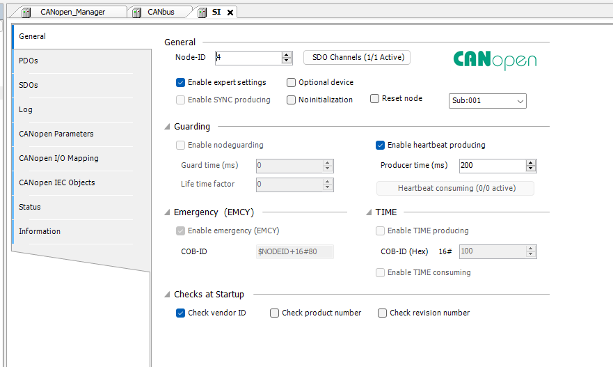
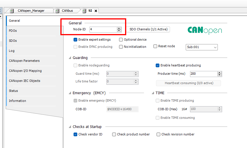
Set the Node-ID of the CET sensor in General → Node-ID. We will use the sensor’s default value 4.
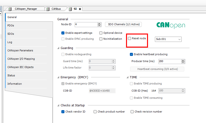
Also, uncheck the Reset Node Checkbox in the figure below.
GVL
gHMI
This GVL is for reading and writing HMI, and defines global variables for storing values to be acquired/set via SDO communication, etc. We have prepared arrays for reading and writing of REAL type, BOOL type, and INT type, which are used as temporary storage areas for various parameters. We also define string variables to store the device name, hardware version, and firmware version.
{attribute ‘qualified_only’}
|
|---|
gTSM
This GVL defines variables mapped directly to the input memory area to reference the input data received from the CET5 device on CODESYS. CET5_0_0 treats the 4-byte input data starting from %IB100 as a USINT array, and CET5_0_1 treats the 2-word input data starting from %IW52 as a UINT array. This allows you to reference the received PDO data in byte or word units.
{attribute ‘qualified_only’}
|
|---|
pTSMCET5_ID004
Next, let’s create a program.
VAR
Define the variables for the program used in this article.
PROGRAM pTSMCET5_ID004
|
|---|
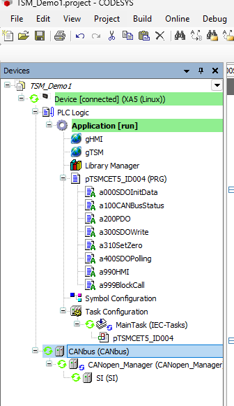
a000SDOInitData
This program is an initialization process that reads device information and communication setting values using SDO communication when the CET5 device starts or when a re-initialization request is made.
SDO_READ_DATA function block, it sequentially reads 1008h, 1009h, 100Ah, 3000h, and 3001h from the object dictionary to obtain the device name, hardware version, firmware version, baud rate, and Node-ID.
Each SDO Read process is executed sequentially by step control, and an initialization completion flag is set when it completes successfully. If an error occurs during processing, it transitions to the initialization error state and stops SDO communication.
fbR_TRIG3(CLK:=
|
|---|
a100CANBusStatus
This program acquires the communication status of the CANopen Manager and the target device, and resets the CAN bus alarm if necessary. Also, it expands the 4-byte position data received via PDO from the CET5 into two INT16 values, Position1 and Position2. Since the position data resolution of the CET5 is 0.1 mm, it divides the acquired integer value by 10 and treats it as real position data rPosition1 and rPosition2 in mm units.
CANMasterStatus:=IoConfig_Globals.CANopen_Manager.KernelState;
|
|---|
a300SDOWrite
This calls the program for writing parameters via SDO.
a310SetZero();
|
|---|
a310SetZero
This program detects the rising edge of the zero point setting request xSensorSetZero, and executes SDO writing using the SDO_WRITE_DATA function block. If SDO writing completes normally, xSensorSetZeroOK is set to TRUE, and if an error occurs, xSensorSetZeroErr is set to TRUE. After processing is complete or an error occurs, it sets SDO_WRITE_DATA.ENABLE back to FALSE to prepare for the next request.
fbR_TRIG(CLK:=xSensorSetZero);
|
|---|
a399StoreParams
This program sets the string “save” used for the parameter save command to the byte array arrdata000. By writing this data to 1010h:01h via SDO_WRITE_DATA2, it requests parameter saving to the non-volatile memory inside the sensor. If SDO writing completes normally, xParametersStoreOK becomes TRUE, and if an error occurs, xParametersStoreError becomes TRUE.
arrdata000[0]:=16#73;
|
|---|
a400SDOPolling
In this program, after the CET5 device initialization is complete, error information is periodically read via SDO communication. It acquires the number of errors registered in the error history from 1003h:00h from the error history, and acquires the state of the Error Register from 1001h:00h.
In normal operation, it repeats reading at a 500ms cycle, and if an SDO communication error occurs, it stops SDO Read once, then waits for 500ms and retries.
IF iSDOReadPollingStep > 0 AND TO_INT(SDO_READ_DATA2.ERROR)<>0 THEN
|
|---|
a990HMI
In this program, information acquired from the CET5 device, communication status, position data, error information, and operation results are transferred to the HMI global variable gHMI.
It also reflects operation requests from the HMI side to internal PLC control variables.
gHMI.TSM_4_strDeviceName:=strDeviceName;
|
|---|
a999BlockCall
In this program, the function blocks for SDO reading for initialization, SDO reading for error information polling, SDO writing for zero point setting, and SDO writing for parameter saving are called.
SDO_READ_DATA.NETWORK:=1;
|
|---|
Download
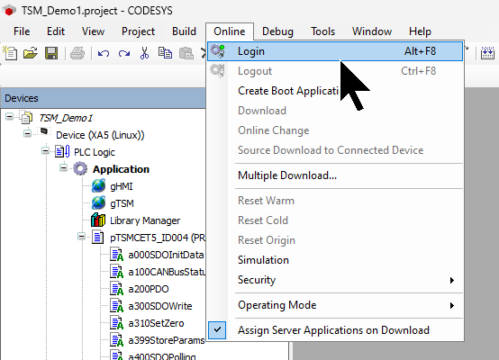
Finally, download the project to the Codesys Runtime with Online → Login.
Results
Communication between the Codesys Runtime and the TSM CET5 sensor has been established.
EXOR side
Next, build the HMI on the EXOR side.
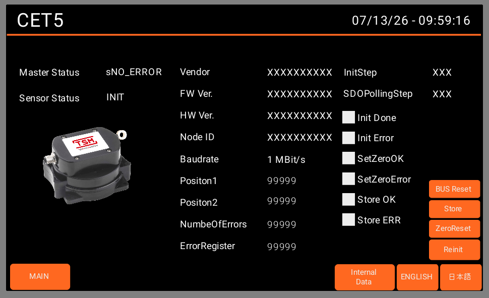
Screen
This is the screen created for this article.
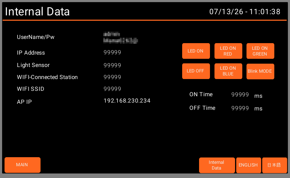
LED variable
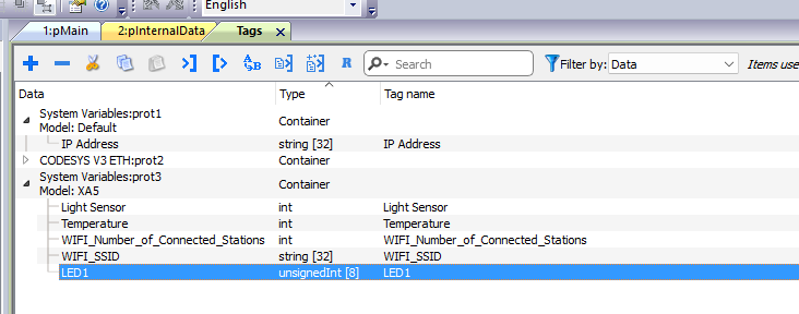
Although it was not used in this article, I defined an LED variable specifically for XA5.
Results
You can check the operation in this video.
Download
You can download the project created in this article from the link below.
https://github.com/soup01Threes/Codesys/blob/main/Demo_TSM_CET5_XA5.zip