This is a new series of articles using the PSR-M-B3-SDI8-SDO4-DO4-PI safety module from Phoenix Contact. We will start with tool installation and simple program creation.
Now, let’s enjoy factory automation.
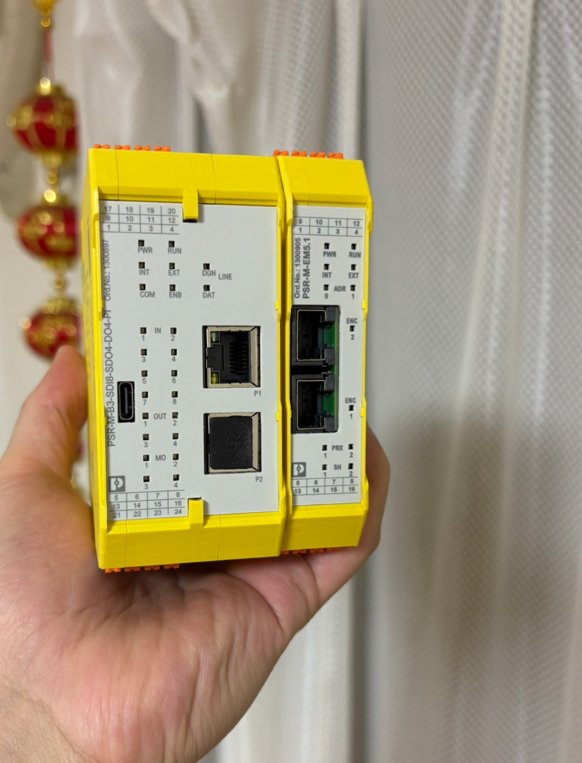
PSR-M-B3-SDI8-SDO4-DO4-PI?
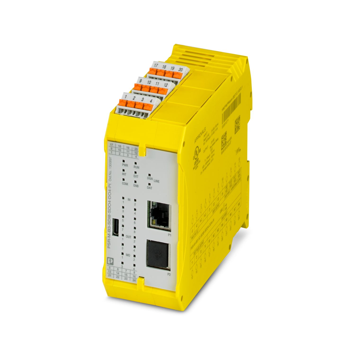
The Phoenix Contact PSR-M-B3-SDI8-SDO4-DO4-PI is a configurable safety module (basic module), with 8 SDIs, 4 SDOs, 4 reset inputs or 4 signal outputs, 4 clock outputs, expandable via TBUS, up to SIL 3, Cat.4/PL e, plug-in push-in terminal blocks. Note that the TBUS connector is not included.
The configurable and individually expandable PSRmodular safety system is a flexible safety solution for monitoring machines and systems. The freely configurable base module is used for monitoring various safety equipment such as emergency stops, safety doors, and light grids. The base module is equipped with safety inputs/outputs, signal outputs, and clock outputs.
Structure
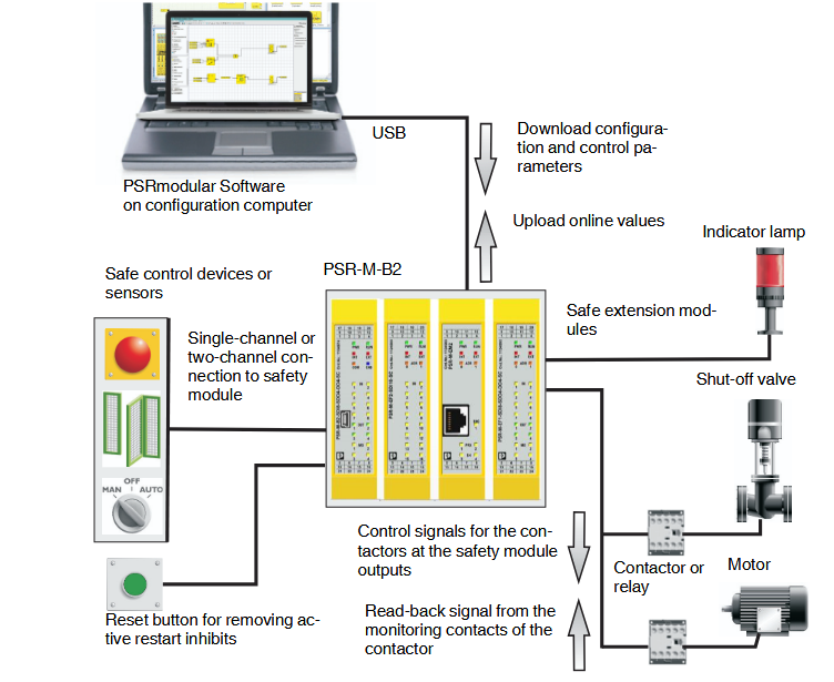
The PSRmodular safety system consists of the following components.
- PSR-M-B1, PSR-M-B2, PSR-M-B3 base modules
- Optional PSR-M-EF, PSR-M-EM, PSR-M-TBUS safety extension modules or PSR-M-E standard extension modules
- PSRmodular configuration software
- Safety control equipment, sensors, and actuators (depending on the application)
The figure below shows the overall system in an application example using the PSR-M-B1 or PSR-M-B2.
Wiring Block
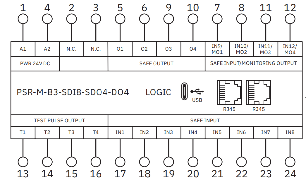
This is the wiring block for the PSR-M-B3-SDI8-SDO4-DO4-PI.
ツールダウンロード
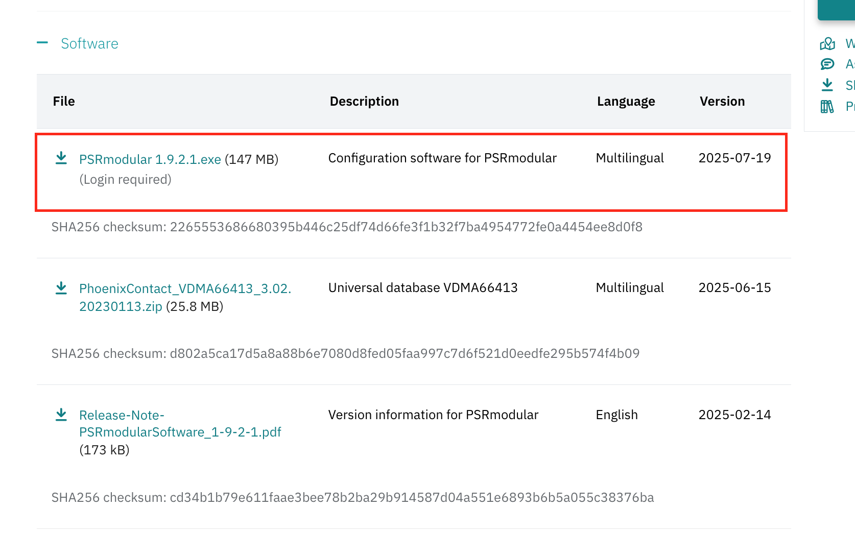
To use the PSR-M-B3-SDI8-SDO4-DO4-PI, please download the dedicated software from the Phoenix Contact website.
https://www.phoenixcontact.com/ja-jp/products/psr-m-b3-xc-sdi8-sdo4-do4-pi-1337855
Installation
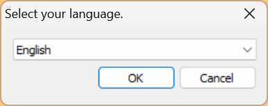
Next, we will install PSRModular. Select the language and click OK to proceed.
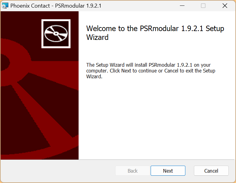
Proceed with Next>.
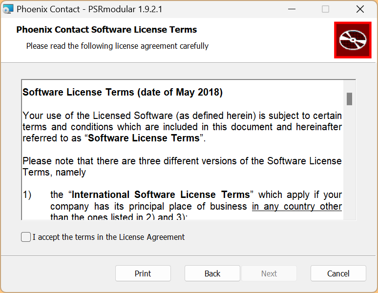
Agree to the license and proceed with Next.
Proceed with Next>.
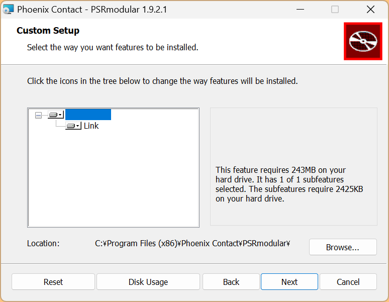
Click Install to start.
Please wait a moment…
Done!
E-STOP Function Block (Emergency Stop)
This is the E-STOP function block used in this article. The E-STOP function block checks the state of the “IN” input of the emergency stop device. If the emergency stop button is pressed, the “OUT” output becomes logic “0”. Otherwise, the output is logic “1”.
Input Type
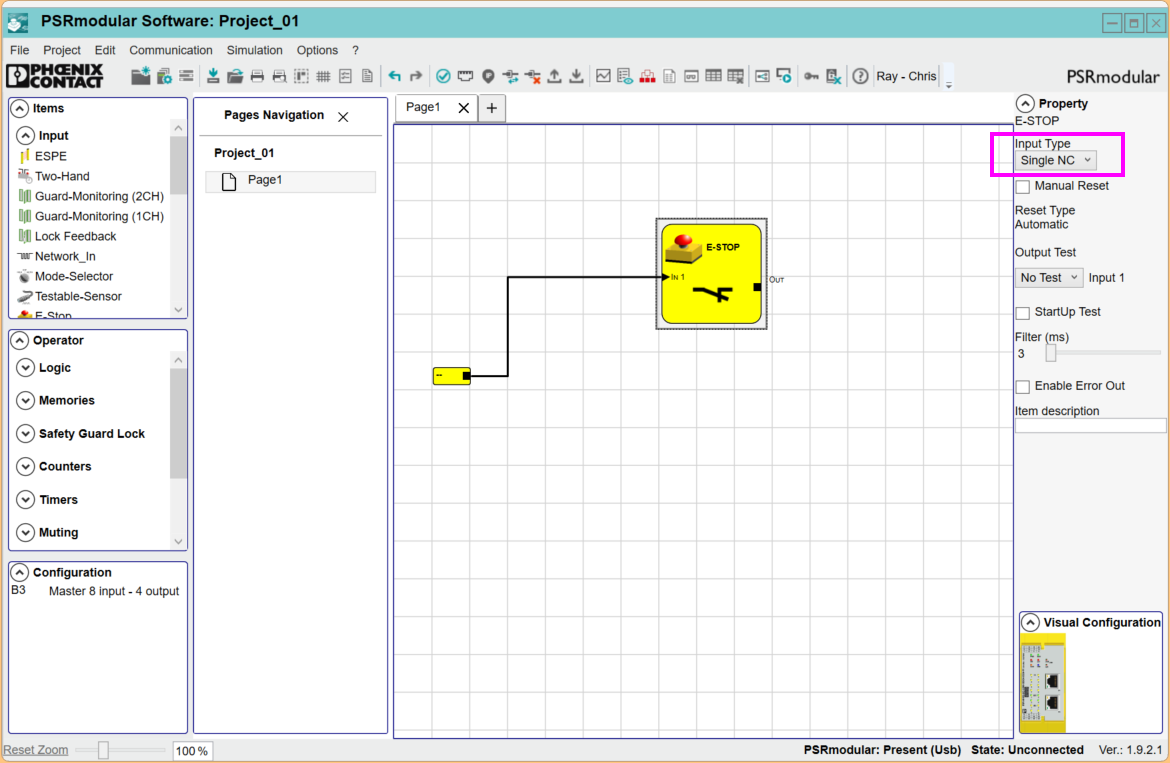
Single NC
Enables connection of a single-channel emergency stop button.
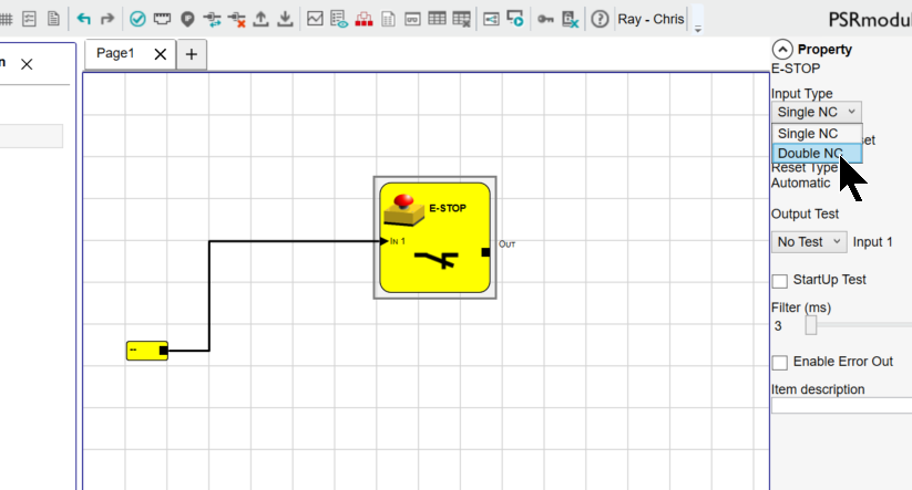
Double NC
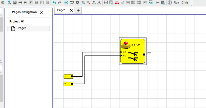
Enables connection of two-channel emergency stop buttons.
Manual reset
If this option is selected, a manual reset must be performed every time the function block becomes active. Otherwise, the output activation directly follows the state of the input.
Reset Type
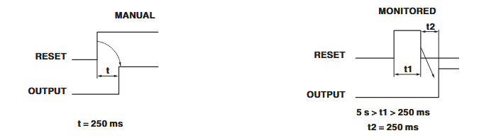
There are two types of reset: “Manual” and “Monitored”.
If the “Manual” option is selected, only the signal transition from logic “0” to logic “1” is checked. If the “Monitored” option is selected, a double transition from logic “0” to logic “1” and a return to logic “0” are checked.
Output Test
Allows selection of the clock signal to be connected to the emergency stop button. These additional diagnostics enable the detection of short circuits or cross circuits between cables. To enable these diagnostics, the clock signal must be configured in the “Properties” window of the relevant function block.
StartUp Test
If this option is selected, it is required before the function test of the emergency stop button is enabled. This check is only required during machine startup.
Filter (ms)
This option allows filtering of external input signals. The filter can be set between 3 and 250 ms and helps suppress contact bouncing. The length of the filter time affects the calculation of the safety function’s response time.
With simultaneity / Simultaneity ms
This parameter is only valid if the “Double NC” option is selected. In this case, the block monitors the simultaneous switching of both input channels.
If the signal change does not occur on both input channels within the defined synchronization time, the enable signal is not output. The maximum time interval between the two input channels can be set in the range of 10ms to 7000ms.
Enable Error Out
If this parameter is selected, an output (“ERROR”) is available to signal that an error has been detected by the function block.
Item Description
Here, you can enter a 24-character text description or name for the function. The text is displayed above the function block.
SINGLE/DUAL-OUTPUT Function Block (Safety Output)
This block can only be used in combination with the PSR-M-B2 base module and the PSR-M-EF1 and PSR-M-EF5 extension modules.
The safety-related output is implemented as a digital semiconductor output. The function block output “OUT 1” supplies a logic “1” signal when the terminal point “IN” is controlled to logic “1”. When the input signal “IN” is controlled to logic “0”, the output changes to logic “0”.
Each “SINGLE/DUAL-OUTPUT” safe function block has a corresponding “FBK_RST” input. This input is only displayed when a manual reset or external K-time monitoring is externally initiated.
Manual reset
If this option is enabled, the “FB-K_RST” input must detect a rising edge to control the outputs (“OUT 1” and “OUT 2”) every time the signal changes (1→0→1) at the “IN” input. If this option is disabled, the output enable directly follows the input condition at the terminal point “IN” (“Reset Type”: “Automatic”).
Reset Type
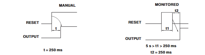
There are two types of reset: “Manual” or “Monitored”. If the “Manual” option is selected, only the signal transition from logic “0” to logic “1” is checked. If the “Monitored” option is selected, a double transition from logic “0” to logic “1”, and then back to logic “0”, is checked.
Enable Monitoring-Out
If this option is selected, the status output of the function block indicates the status of the safety output. This status information can be used for diagnostic purposes.
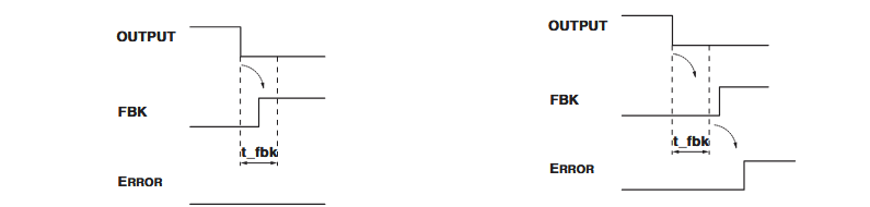
External K time monitoring
If this option is selected, a time window for monitoring the external feedback signal can be specified.
- When the output changes to logic “1” status, the feedback signal (“FBK_RST”) must change from logic “1” to logic “0” (or vice versa) within the specified time.
- If an error occurs (e.g., the signal does not change), the output is set to logic “0”, and an error is indicated on the base module by the EDM LED (PSR-M-B1) of that output flashing.
Enable Error Out
Each “SINGLE/DUAL-OUTPUT” safe function block has a corresponding “FBK_RST” input. This input is only displayed when a manual reset or external K-time monitoring is externally initiated.
Application Start
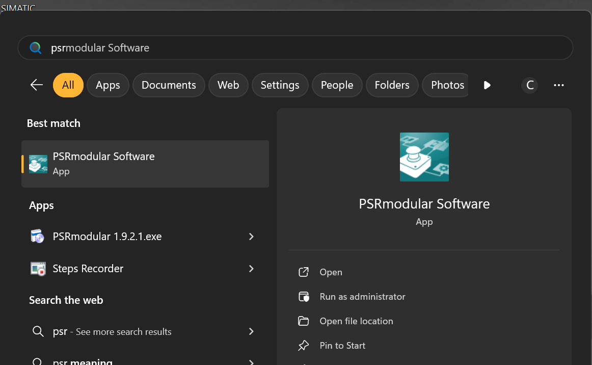
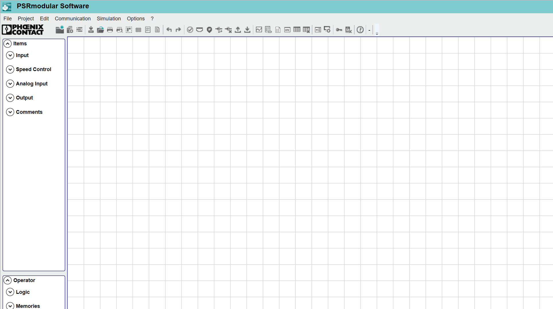
Now let’s actually start the PSRmodular Software.
Done!
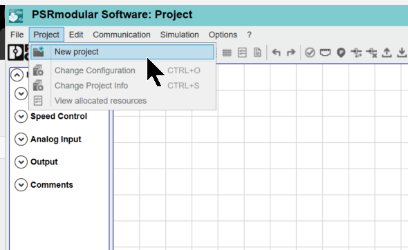
Create New Project
To create a new project, go to Project>New Project.
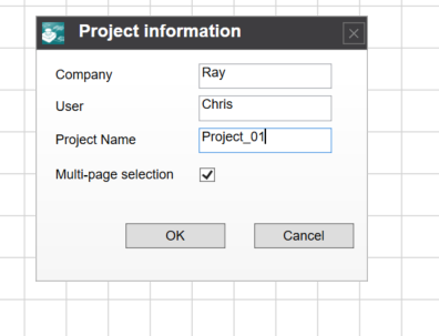
Enter information such as the Company and User name.
Next, set the CPU type.
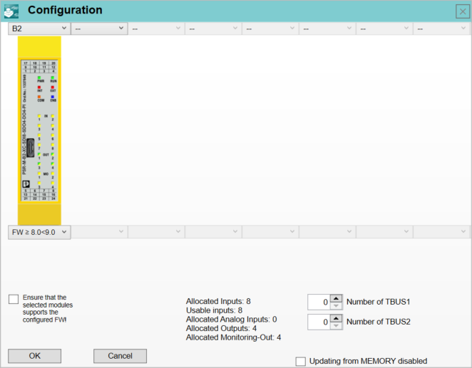
Module Selection
Set the CPU type from the Drop-List in the figure below. In this article, we will use the B3 type.
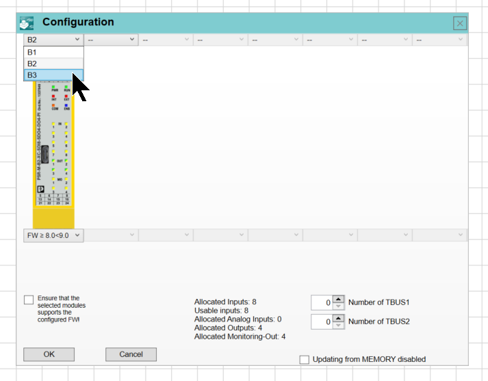
That’s all set.
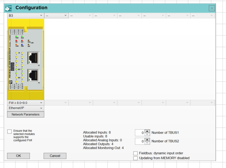
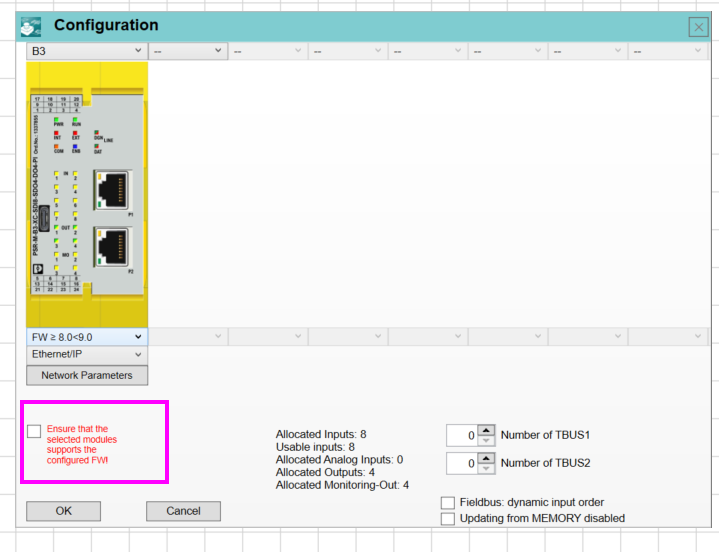
Check the CHECK BOX in the red frame, click OK, and create the project.
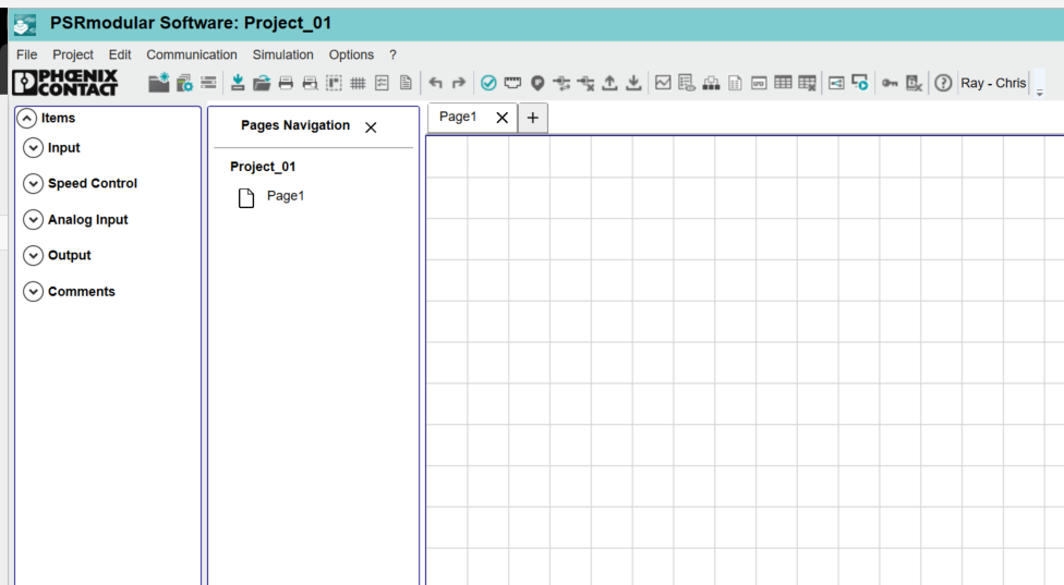
Done! A new project has been created.
USB Connection
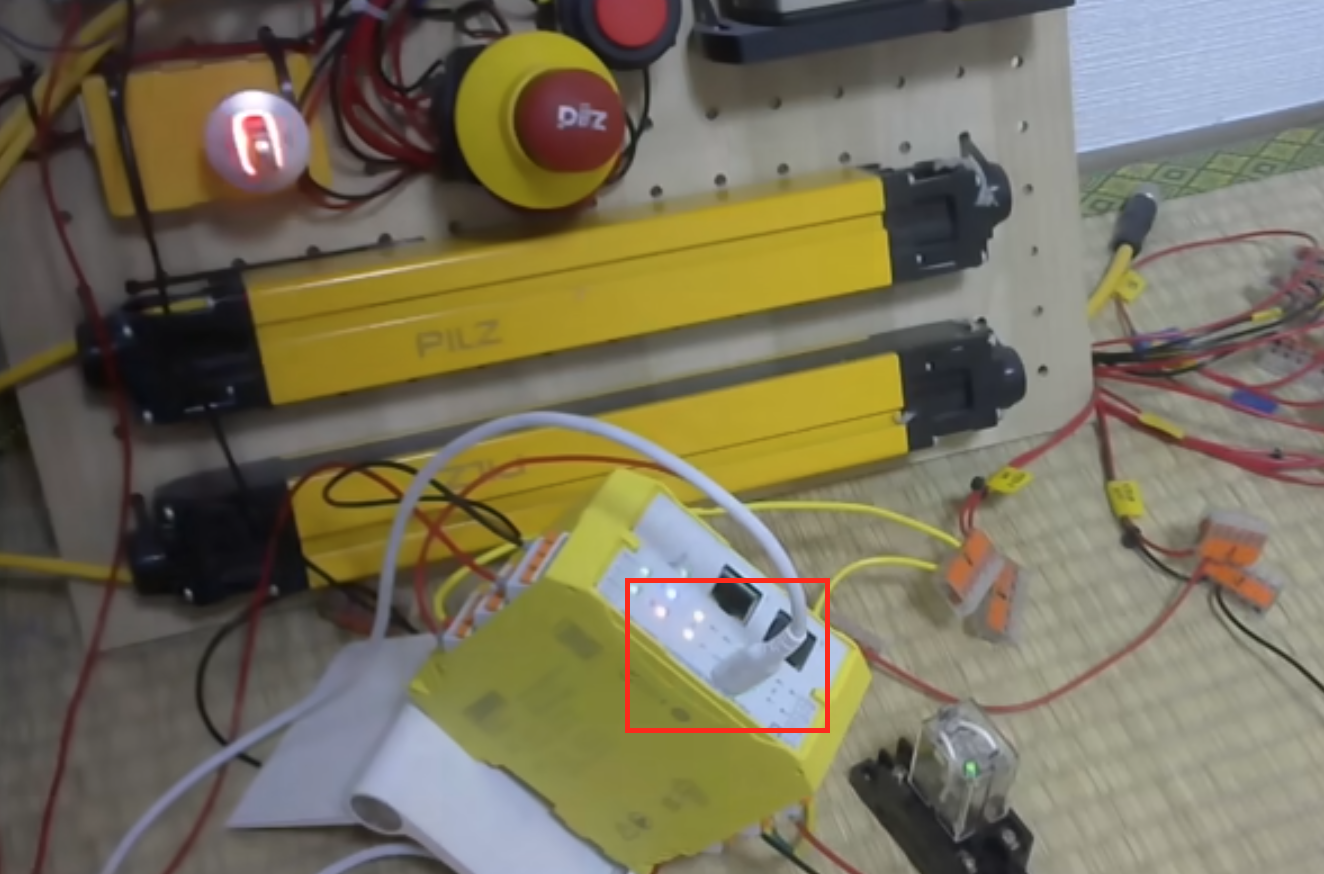
Connect the PC and the PSR-M-B3-SDI8-SDO4-DO4-PI unit via the USB-C type port.
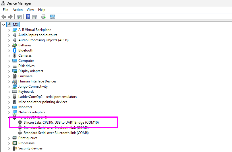
Check if the USB driver has been installed from Device Manager.
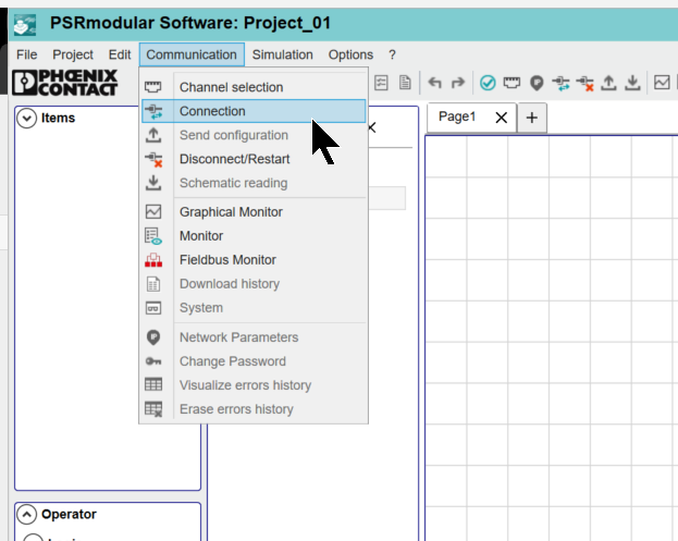
Connect the PC and the PSR-M-B3-SDI8-SDO4-DO4-PI via Communication>Connection.
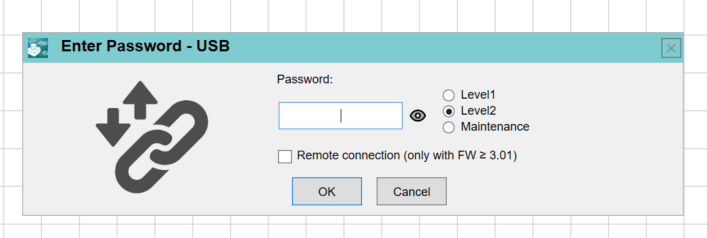
You will be prompted to enter the Password. The default is SAFEPASS.
Done! The PC and the PSR-M-B3-SDI8-SDO4-DO4-PI are connected.
Level 1 password
The Level 1 password allows the user to change and save the load process (from the base module to the PC) and the project on the PC. The password allows viewing of log files (load process and system error messages) in the text-based and graphical monitor views in online mode.
Level 2 password
The Level 2 password allows the user to send the configuration (from the PC to the base module) and to change and save the project. A user who knows the Level 2 password has the right to enter a new Level 2 password (single-byte numbers, maximum 8 characters). The Level 2 password provides the user with access to all Level 1 functions, as well as the option to change the password.
Wiring
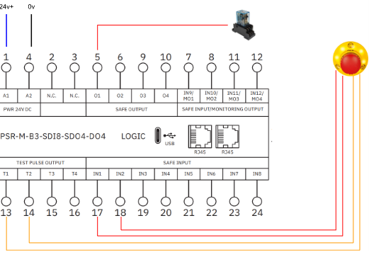
In this article, we will wire the emergency stop and an OMRON relay.
ESTOP Program
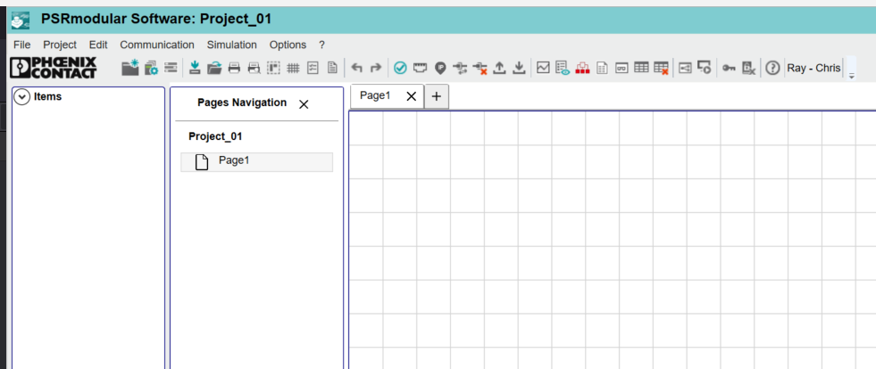
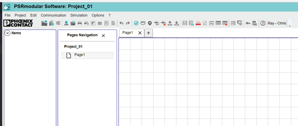
Now we will create the program from Page 1 of the project.
Add ESTOP Component
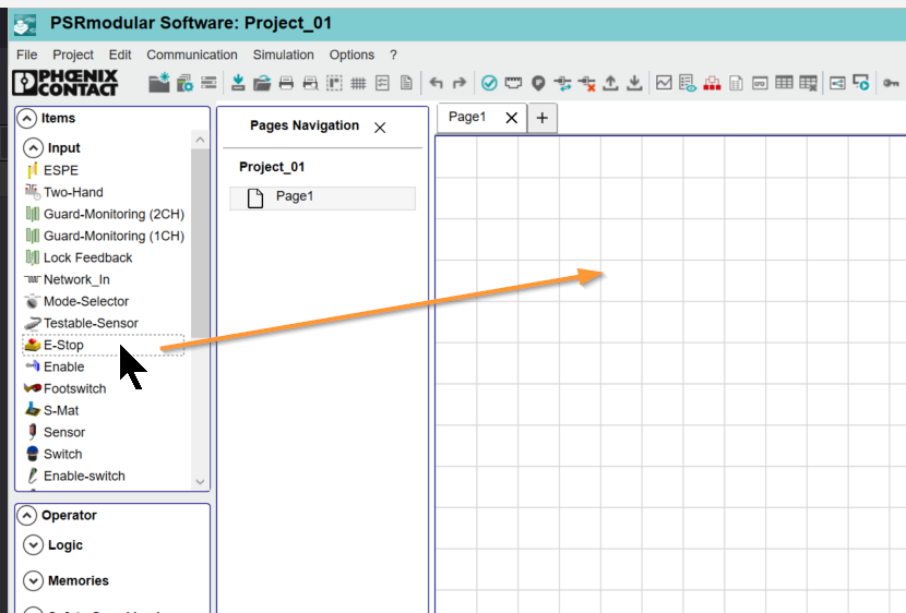
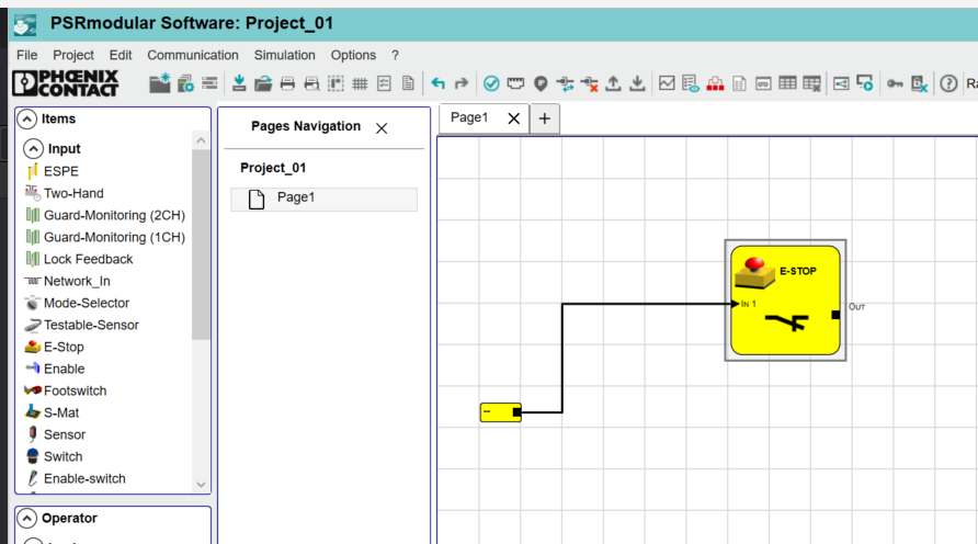
Add the E-STOP component from Items>Input.
Done!
Input Type
First, select the ESTOP component > the Property screen will be displayed on the right.
Since we are using a 2-channel emergency stop in this article, select Double NC from the Input Type Drop-list.
Done!
Done!
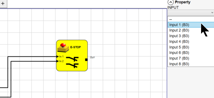
Next, set the safety input terminal block number connected to the ESTOP component.
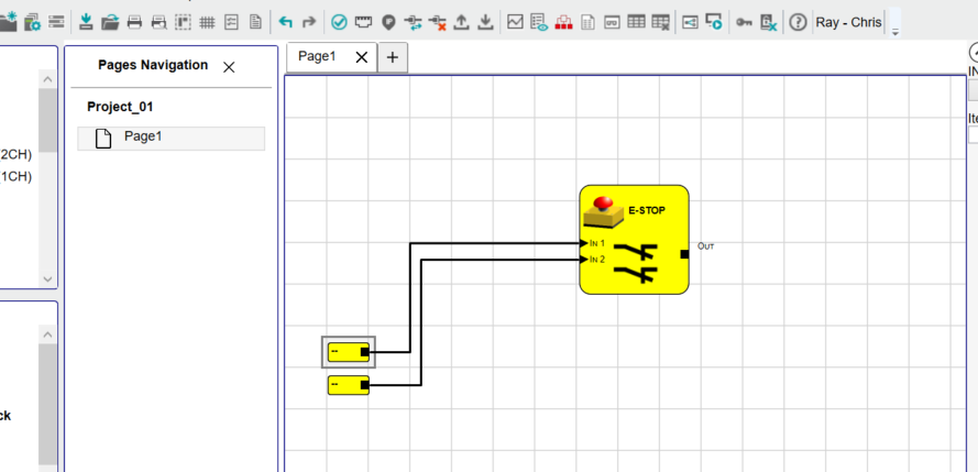
Select the terminal block number from the Drop-list.
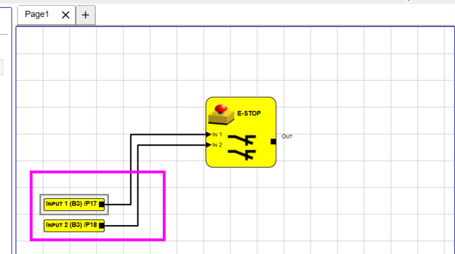
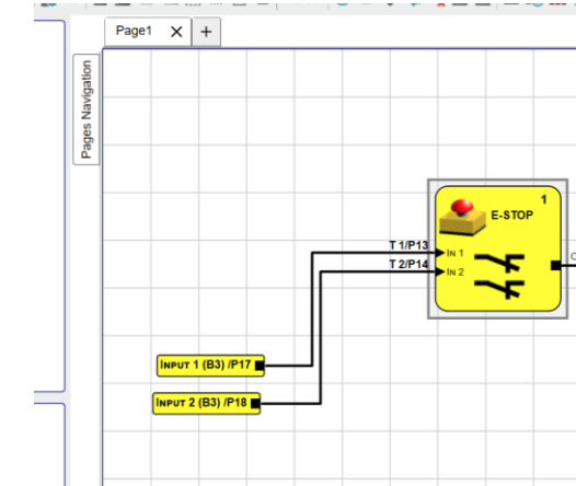
Done! In this article, the 2-channel emergency stop is connected to Input 1 (terminal block number 17) and Input 2 (terminal block number 18).
Output Test
Next, enable the Output Test function. This can be set from the Drop-List.
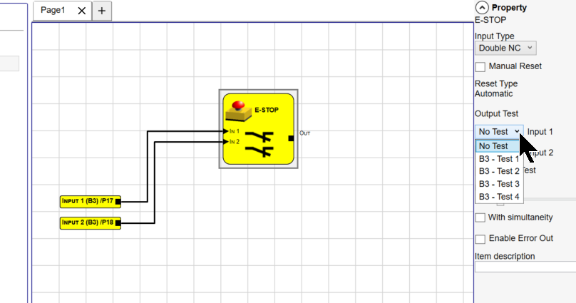
In this article, the 2-channel emergency stop is connected to Test 1 (terminal block number 13) and Test 2 (terminal block number 14).
Output
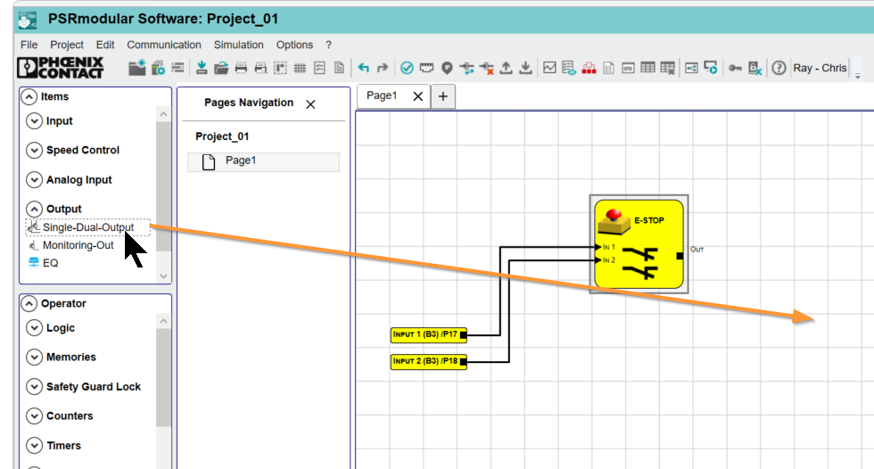
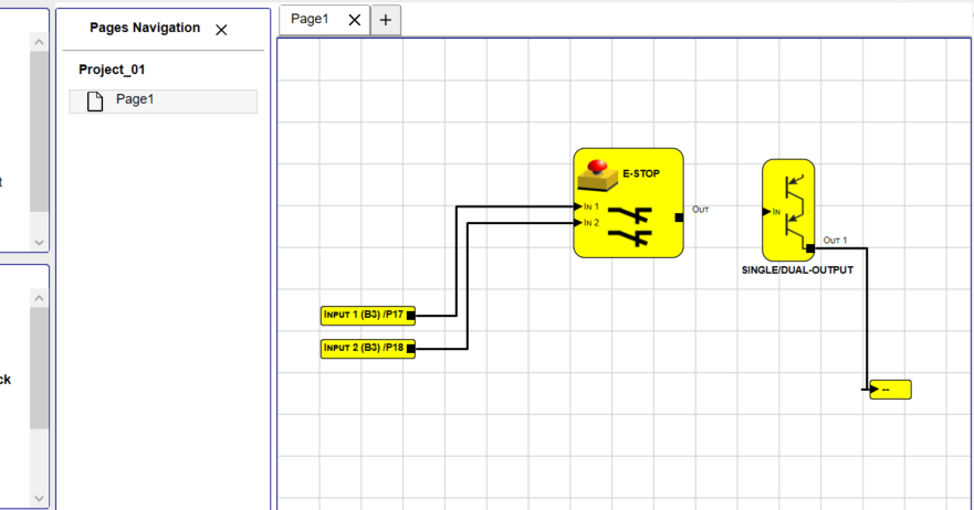
Next, add Output>Single-Dual-Output to the project.
Done!
Conenct
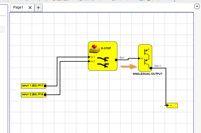
Connect the output of the ESTOP component as the trigger condition for the Single-Dual-Output.
Connector
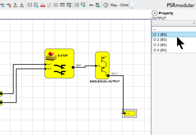
Next, set the Output terminal block number for the Single-Dual-Output.
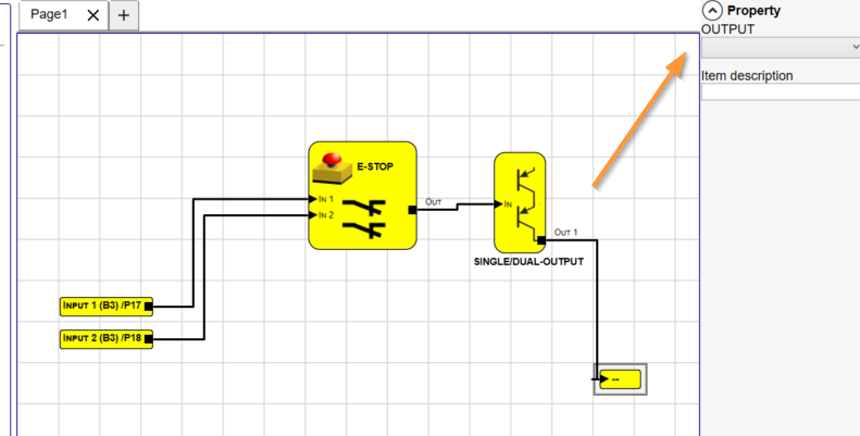
In this article, the Single-Dual-Output is connected to O1 (terminal block number 5).
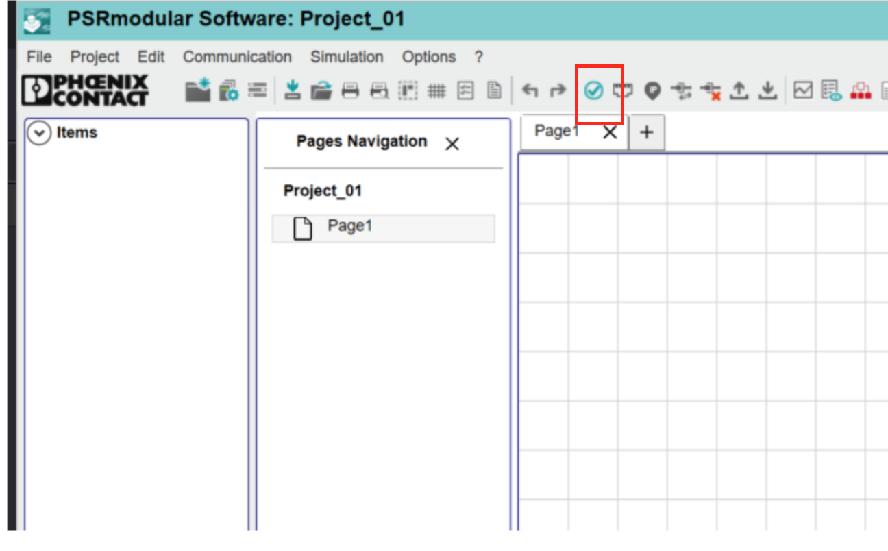
Compile
Click the button shown in the figure below to compile the project.
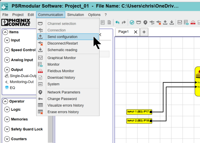
Download
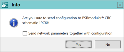
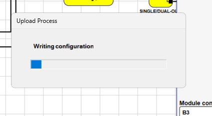
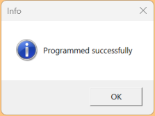
Finally, download the project to the PSR-M-B3-SDI8-SDO4-DO4-PI via Communication>Send Configuration.
Proceed with Yes.
Please wait a moment…
Done!
Results
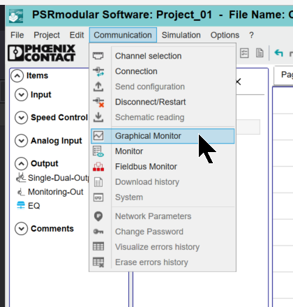
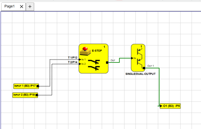
Monitor the program via Communication>Graphical Monitor.
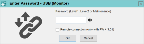
Passwordを入力します。
Done!
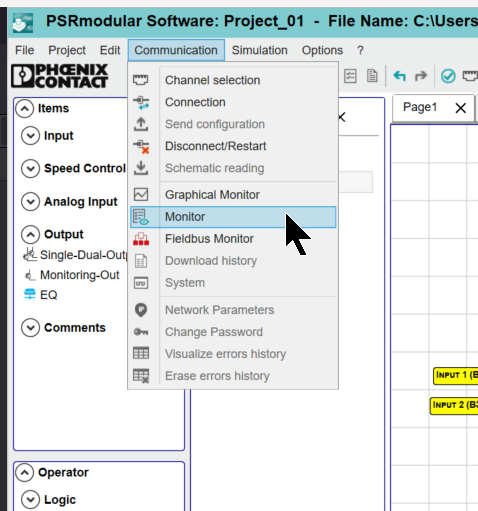
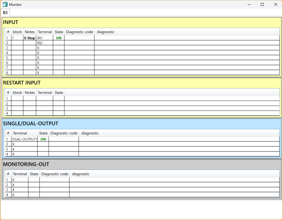
You can also monitor components in bulk by clicking Communication>Monitor.
Done!
Please check the operation with this video.