Hello and here is my Part 6 of Beckhoff TwinCAT x Siemens S210.
Last time I uploaded Beckhoff IPC data to WAGO Cloud via WAGO PFC Controller 720-8215 Modbus TCP, but this time I’m thinking of storing the data in a local PC.
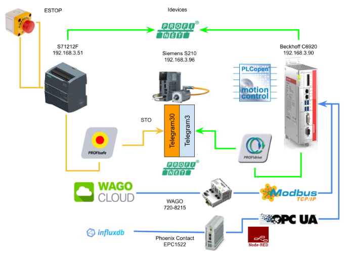
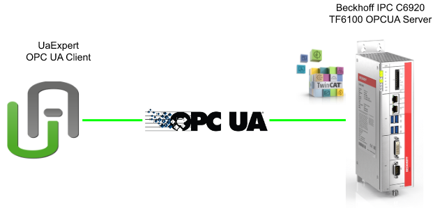
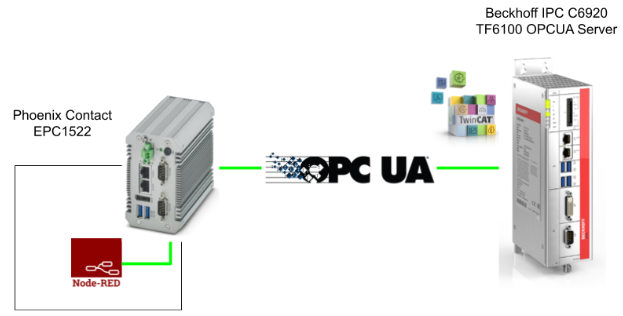
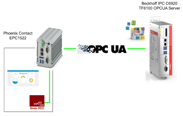
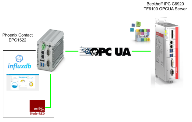
In the configuration, the OPC UA Server is configured with TF6100 from Beckhoff TwinCAT, and the OPC UA Node is collected as a structure from Node-RED built in Phoenix Contact EPC1522 and saved in InfluxDB. Let’s start!
Thanks!
Because of Beckhoff Japan ,Phoenix Contact Japan and mana Design works that lend the devices to me – I can create this post.
Beckhoff Japan
IPC6920-005 was lent by Beckhoff Japan, a Japanese subsidiary of Beckhoff. Founded in 1980, Beckhoff Automation is a German company at the forefront of the introduction of open automation systems based on PC-based control technology.
Beckhoff Japan Corporation Beckhoff Automation Co., Ltd. established its head office in Yokohama in 2011 and the Nagoya office in 2017.

Here is the Home page of Beckhoff Japan.
https://www.beckhoff.com/ja-jp/
Mana Design Works
Siemens SINAMICS S210 was lent by Mana Design Works.
Mana Design Works is an official solution partner of Siemens ,headquartered in Osaka, and always make optimal proposals with Siemens CPUs, HMIs, Drives, Motion Controllers, and SCADA.

Here is the homepage of Mana Design works.
Phoenix Contact Japan
The EPC1522 Edge PC used in this article was lent by Phoenix Contact Japan.
Phoenix Contact is a global company with 55 locations worldwide and 20,300 employees,Founded in Germany in 1923..
Under the concept of “All Electric Society”, Phoenix Contact aim to provide comprehensive solutions such as electrification, networking, and realization of automation in all industrial sectors. Products from Phoenix Contact are used in a wide variety of applications, such as industrial production equipment, infrastructure, energy and electronics connections.
Phoenix Contact Co., Ltd. in Japan was established in Yokohama in December 1987 as the first local subsidiary in Asia, and currently has 10 sales offices in Japan.
Here is the HP:
https://www.phoenixcontact.com/ja-jp/

Video
English Version
Part4
Beckhoff.TwinCAT3 x Siemens S210 Servo Drive part4 – Idevices Configuration.EN
Part3
Beckhoff.TwinCAT3 x Siemens S210 Servo Drive part3 – PLCOPEN to Control the Drive in TwinCAT.EN
Part2
Beckhoff.TwinCAT3 x Siemens S210 Servo Drive part2 – Shared Devices,Profisafe.EN
Part1
Beckhoff.TwinCAT3 x Siemens S210 Servo Drive part1.EN
Japanese Version
Part4
Beckhoff.TwinCAT3 x Siemens S210 Servo Drive part4 – Idevices Configuration.JP
Part3
Beckhoff.TwinCAT3 x Siemens S210 Servo Drive part3 – PLCOPEN to Control the Drive in TwinCAT.JP
Part2
Beckhoff.TwinCAT3 x Siemens S210 Servo Drive part2 – Shared Devices,Profisafe.JP
Part1
Beckhoff.TwinCAT3 x Siemens S210 Servo Drive part1.JP
Reference Link
Japanese Version
Project#Beckhoff TwinCAT3 x Siemens S210 Servo Drvie_Part2 |
English Version
Project#Beckhoff TwinCAT3 x Siemens S210 Servo Drvie_Part2 |
Project#Beckhoff TwinCAT3 x Siemens S210 Servo Drvie_Part1 |
OPCUA
OPC UA Clients
The Client application is implemented for OPC UA access, and uses the Client API to receive and send OPC Server Services.
Please note that the Client API is an internal interface, the purpose of which is to separate the Client application program and the OPC UA Communication Stack.
The OPC UA Communication Stack also uses its Client API to transfer messages from the OPC UA Server to the Client application.

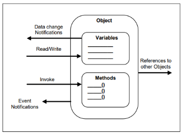
Object Model
From the OPC UA Server’s point of view, this Object Model is the most standard way to represent your “Object”. The OPC UA Object Model is exactly the design of the “Object” in the software world, and has Variables and Methods in it, but also Reference between Objects is also possible.
Node Model
Node Model is probably the most used.
The OPC UA Server can be referenced from the OPC UA Client by providing Objects and related information from the Address Space. That is the OPC UA Object Model I mentioned earlier.
And the Object itself can have multiple Nodes.
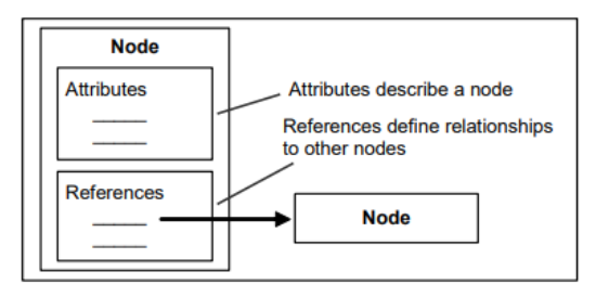
Attributes
Attributes are parts that store the information of Nodes themselves, and OPCUA Client can read and write Attributes, Query, Subscription, Monitor, etc. Each Attribute also has ID, Attribute Name, and Data Type information.
References
References is a combination of SourceNode、 TargetNode and Reference Type.
OPC UA Servers
This is a concept diagram of the OPC UA Server.
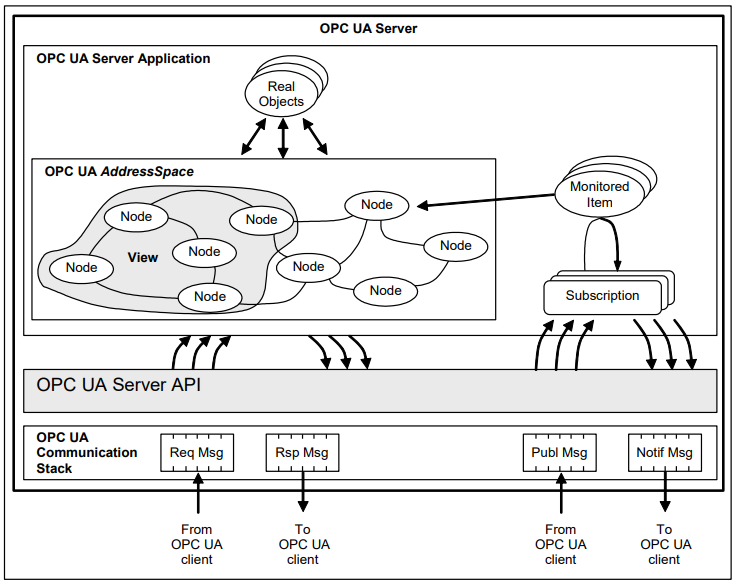
Real Object
Real Objects are Objects that can be accessed in the OPC UA Server application, and conceptually they are your program variables.

OPC UA Server Application
The Server application becomes Code that implements the functions of the OPC UA Server, and uses the OPC UA Server API to send and receive OPC UA Messages to the OPC UA Client.
That API is an internal Interface to separate the Server Application Code and the OPC UA Communication Stack.
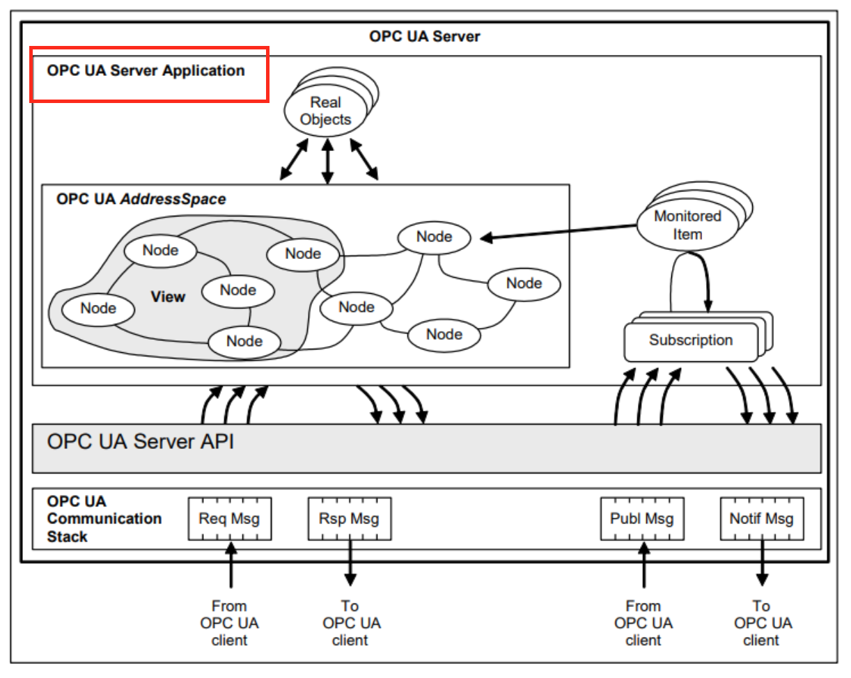
AddressSpace Nodes
AddressSpace allows Server to model multiple Nodes and access from Client. Nodes in AddressSpace represent “Real Objects”.
Built-in Types
Boolean
Boolean represents 0 (False) and other than 0 (True) with 1 byte data. Basically、 the current value is “1” to express True, but values other than 0 are also recognized as True.
Integer
All integer types are also handled in little-endian format、 and Significant Byte targets the 0th byte of Stream. For example、 the 32-bit integer 1000000000 is expressed as 0x3B9ACA00 in Hex and as follows in Stream.

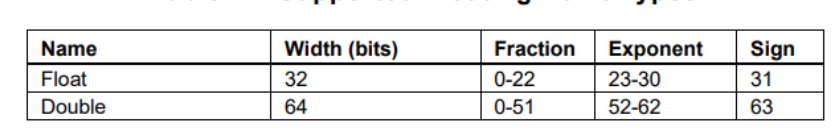
Floating Point
All floating-point values are expressed according to IEEE-754. So there are three parts: Sign/Exponent/Fraction. And all invalid values become NaN.
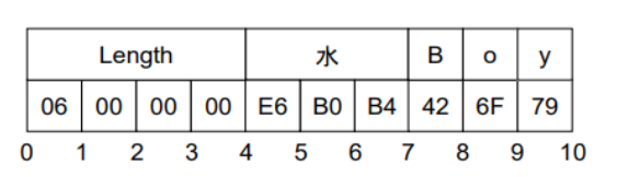
String
All Strings are UTF-8 characters and the length of the string is represented by an Int32 (-1 results in a “Null” string).
DateTime
Data Time is expressed as a 64 Bit Signed integer, January 1,1601 (UTC) in 100 nanoseconds to represent the date. It is important to note that not all development environments can always cover the Data-Time range. For example, in the UNIX time_t structure with pre-1970 dates and 1s precision, OPC UA has the following rules for DateTime.
- If the DateTime variable = 0, the DateTime is at or before 1601−01−01 12:00AM UTC, or the smallest DateTime value that the development environment can represent.
- If the DateTime variable is an Int64 MAX range, the DateTime will be 9999−12−31 11:59:59PM UTC, or the largest DateTime value your development environment can represent.
ExtensionObject?
Extension Object is one of the major functions of OPC-UA, and can convert OPC UA Server variables into a Data Model. An Extension Object is a “structure”, so it’s easy to understand. For example, there are various information such as Speed, Position, and Status in Motor, and they can be accessed from OPCUA Client with “Motor1” and “Motor2”.
Implementation-1
First, we will start the OPC UA Server from Beckhoff TwinCAT and access it from UaExpert.
TwinCAT Side
Add DUT
Add a new folder with DUTs > right click > New Folder. This is also the best part of TwinCAT, where folders, DUTs, POUs, and GVLs can be created wherever you like, which is convenient in terms of data management.

A folder called DUT_OPCUA has been added.
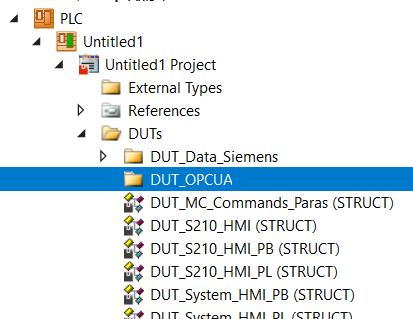
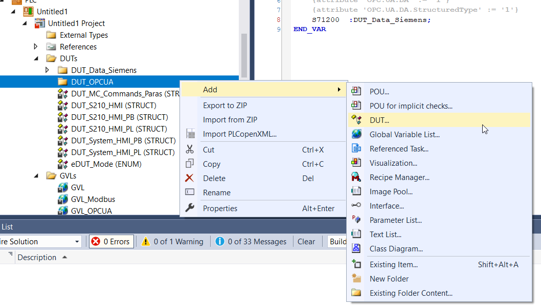
Select Folder > Right click > DUT to add DUT.
DUT_Data_ToSiemens_OperCommands_OPCUA
This is the command data that TwinCAT sends to Siemens via Idevices. I created a DUT similar to the previous article, but changed the data type of the variable from BIT to BOOL.
| TYPE DUT_Data_ToSiemens_OperCommands_OPCUA : STRUCT Reset :BOOL; _n1,_n2,_n3,_n4,_n5,_n6,_n7:BOOL; END_STRUCT END_TYPE |
DUT_Data_ToSiemens_OPCUA
This is the OPC UA Version of the DUT that summarizes the data that TwinCAT sends to Siemens via Idevices.
| TYPE DUT_Data_ToSiemens_OPCUA : STRUCT OperCommands :DUT_Data_ToSiemens_OperCommands; _NotUsed :ARRAY[0..18]OF BYTE; END_STRUCT END_TYPE |
DUT_DataFromSiemens_CPUStatus_OPCUA
This is the command data that Siemens sends to TwinCAT via Idevices. I created a DUT similar to the previous article, but changed the data type of the variable from BIT to BOOL.
| TYPE DUT_DataFromSiemens_CPUStatus_OPCUA : STRUCT STO :BOOL; SS1 :BOOL; SLS :BOOL; SLT :BOOL; internalEventAcknowledge:BOOL; Run :BOOL; ERROR :BOOL; Maint :BOOL; NotUsed :BOOL; END_STRUCT END_TYPE |
DUT_DataFromSiemens_ESTOP_OPCUA
This is the OPC UA Version of the DUT that summarizes the ESTOP Status that Siemens sends to TwinCAT via Idevices.
| TYPE DUT_DataFromSiemens_ESTOP_OPCUA : STRUCT TimeSettingError :BOOL; AckNotEnable :BOOL; AckMissingEnable :BOOL; AckRequired :BOOL; QState :BOOL; _NoUsed1 :BOOL; _NoUsed2 :BOOL; _NoUsed3 :BOOL; State :BYTE; END_STRUCT END_TYPE |
DUT_OPCUA_S71200_OPCUA
This is the OPC UA Version of the DUT that summarizes all Data that Siemens sends to TwinCAT via Idevices.
| TYPE DUT_OPCUA_S71200_OPCUA : STRUCT operCommands:DUT_Data_ToSiemens_OPCUA; ESTOP :DUT_DataFromSiemens_ESTOP_OPCUA; CPUStatus :DUT_DataFromSiemens_CPUStatus_OPCUA; END_STRUCT END_TYPE |
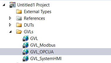
GVL
Now we can create a GVL for the OPC UA Data Exchange.
Declare the DUT defined earlier as a variable.
| {attribute ‘qualified_only’} VAR_GLOBAL {attribute ‘OPC.UA.DA’ := ‘2’} {attribute ‘OPC.UA.DA.StructuredType’ := ‘1’} {attribute ‘OPC.UA.DA.Description’ := ‘Complex (structured) type ‘} S210_1 :DUT_OPCUA_S210; {attribute ‘OPC.UA.DA’ := ‘1’} {attribute ‘OPC.UA.DA.StructuredType’ := ‘1’} S71200 :DUT_OPCUA_S71200_OPCUA; END_VAR |
MAIN
Here is the program to transfer the data from internal to the OPC UA Server.
| PROGRAM MAIN VAR Axis :AXIS_REF; END_VAR VAR PNController :FB_PNController_Status; PNDevices_S210 :FB_PnDevices_Status; PNDevices_S71200:FB_DataFromSiemens; S210 :FB_MyS210; Mode :eDUT_Mode; autocmd:BOOL; autosst :DINT; istep:DINT; TON :TON; Data :DUT_Data_Siemens; END_VAR IF NOT PNDevices_S71200.STOOK THEN istep:=0; GVL_SystemHMI.PB.AutoStart:=FALSE; autosst:=0; END_IF GVL_SystemHMI.PL.ModeAuto:=GVL_SystemHMI.PB.Mode = eDUT_Mode.Auto; GVL_SystemHMI.PL.ModeManual:=GVL_SystemHMI.PB.Mode = eDUT_Mode.Manual; GVL_SystemHMI.PL.Reset:=GVL_SystemHMI.PB.Reset; GVL_SystemHMI.PL.PowerOn:=S210.qStatus.Operational; GVL_SystemHMI.PL.AutoStart:=istep<>0; IF GVL_SystemHMI.PL.ModeAuto THEN Mode:=eDUT_Mode.Auto; ELSIF GVL_SystemHMI.PL.ModeManual THEN Mode:=eDUT_Mode.Manual; END_IF; IF Mode=eDUT_Mode.Auto THEN CASE istep OF 0: TON(IN:=GVL_SystemHMI.PB.AutoStart,PT:=T#1S); IF TON.Q THEN istep:=10; TON(in:=False); END_IF 10: autosst:=1; IF S210.qActualStation = 1 THEN istep:=15; autosst:=0; END_IF 15: TON(in:=TRUE,PT:=T#1S); IF TON.Q THEN TON(in:=FALSE); istep:=20; END_IF; 20: autosst:=2; IF S210.qActualStation = 2 THEN istep:=25; autosst:=0; END_IF 25: TON(in:=TRUE,PT:=T#1S); IF TON.Q THEN TON(in:=FALSE); istep:=30; END_IF; 30: autosst:=3; IF S210.qActualStation = 3 THEN istep:=35; autosst:=0; END_IF 35: TON(in:=TRUE,PT:=T#1S); IF TON.Q THEN TON(in:=FALSE); istep:=40; END_IF; 40: autosst:=4; IF S210.qActualStation = 4 THEN istep:=45; autosst:=0; END_IF 45: TON(in:=TRUE,PT:=T#1S); IF TON.Q THEN TON(in:=FALSE); istep:=50; END_IF; 50: autosst:=5; IF S210.qActualStation = 5 THEN istep:=55; autosst:=0; END_IF 55: TON(in:=TRUE,PT:=T#1S); IF TON.Q THEN TON(in:=FALSE); istep:=60; END_IF; 60: istep:=10; END_CASE ELSE istep:=0; autosst:=0; END_IF PNDevices_S71200.Reset(Execute:=GVL_SystemHMI.PB.Reset); S210.iPNComOK:=PNController.Ready AND PNDevices_S210.Ready AND PNDevices_S71200.Ready ; S210( iEnable:=TRUE ,bServoON:=GVL_SystemHMI.PB.PowerOn ,bReset:=GVL_SystemHMI.PB.Reset ,Mode:=Mode ,bILAbs:=TRUE ,bILJog:=TRUE ,bILAbs:=TRUE ,bAutoAbsCmd:=autocmd ,iAutoStationCmd:=autosst ,Hmis:=GVL.Hmis ); GVL_Modbus.RealRegister[0]:=S210.qActualPosition; GVL_Modbus.RealRegister[1]:=S210.qActualVelocity; GVL_Modbus.WordRegister[0].0:=S210.qStatus.Error; GVL_Modbus.WordRegister[1].0:=S210.qStatus.Operational; GVL_Modbus.WordRegister[2].0:=S210.qStatus.NotMoving;; GVL_Modbus.WordRegister[3]:=UDINT_TO_WORD(s210.qActualStation); GVL_OPCUA.S210_1.Status:=S210.qStatus; GVL_OPCUA.S210_1.ActualStation:=s210.qActualStation; GVL_OPCUA.S210_1.ActualPosition:=S210.qActualPosition; GVL_OPCUA.S210_1.ActualVelocity:=S210.qActualVelocity; Data:=PNDevices_S71200.Data_Siemens; GVL_OPCUA.S71200.CPUStatus.ERROR:=Data.DataFromSiemens.data.CPUStatus.ERROR; GVL_OPCUA.S71200.CPUStatus.internalEventAcknowledge:=Data.DataFromSiemens.data.CPUStatus.internalEventAcknowledge; GVL_OPCUA.S71200.CPUStatus.Maint:=Data.DataFromSiemens.data.CPUStatus.Maint; GVL_OPCUA.S71200.CPUStatus.Run:=Data.DataFromSiemens.data.CPUStatus.Run; GVL_OPCUA.S71200.CPUStatus.SLS:=Data.DataFromSiemens.data.CPUStatus.SLS; GVL_OPCUA.S71200.CPUStatus.SLT:=Data.DataFromSiemens.data.CPUStatus.SLT; GVL_OPCUA.S71200.CPUStatus.SS1:=Data.DataFromSiemens.data.CPUStatus.SS1; GVL_OPCUA.S71200.CPUStatus.STO:=Data.DataFromSiemens.data.CPUStatus.STO; GVL_OPCUA.S71200.ESTOP.AckMissingEnable:=Data.DataFromSiemens.data.ESTOP.AckMissingEnable; GVL_OPCUA.S71200.ESTOP.AckRequired:=Data.DataFromSiemens.data.ESTOP.AckRequired; GVL_OPCUA.S71200.ESTOP.QState:=Data.DataFromSiemens.data.ESTOP.QState; GVL_OPCUA.S71200.ESTOP.TimeSettingError:=Data.DataFromSiemens.data.ESTOP.TimeSettingError; POU_Modbus(); |
OPCUA Connectivity Project
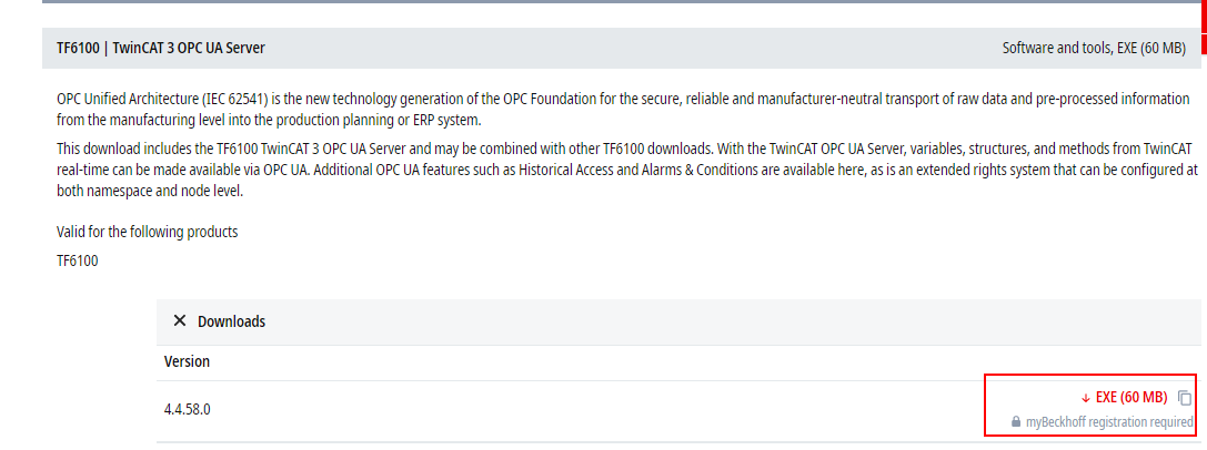
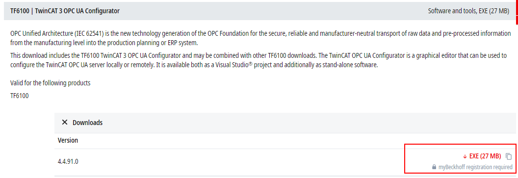
Download and Install TF6100 Packages
Please access this link to download the TF6100 Packages.
TF6100 OPC UA Server
You can find the packages with TwinCAT OPC UA Server and Sample Client functions.
TF6100 OPC UA Configurator
Here is a Package with TwinCAT OPC UA Configuration for the Visual Studio extend function and Standalone applications.
TF6100 OPC UA Gateway
Here is a Package with the TwinCAT OPC UA Gateway function.

Add Connectivity Project
Go to File>New Project to create an OPC UA project.

Choose Empty TwinCAT Connectivity Project>Ok.
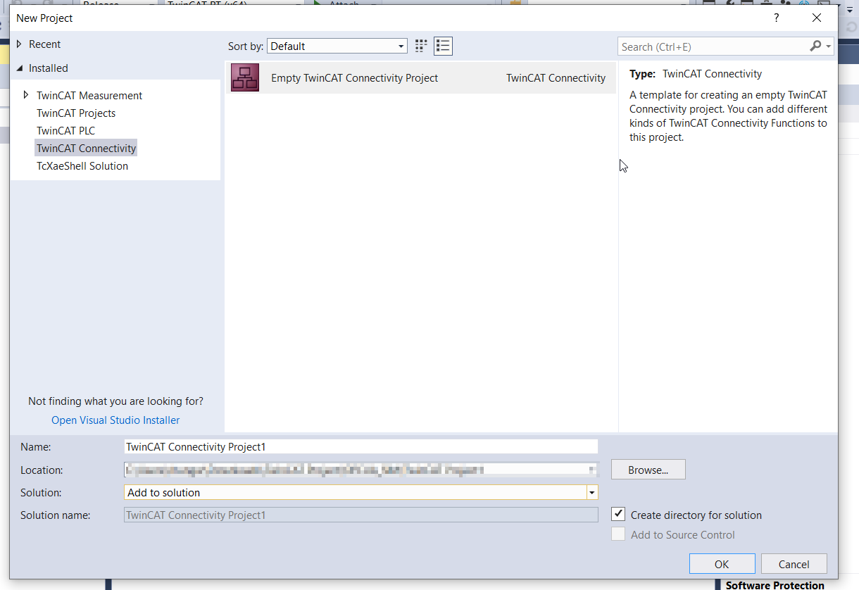
Connectivity Project is inserted.
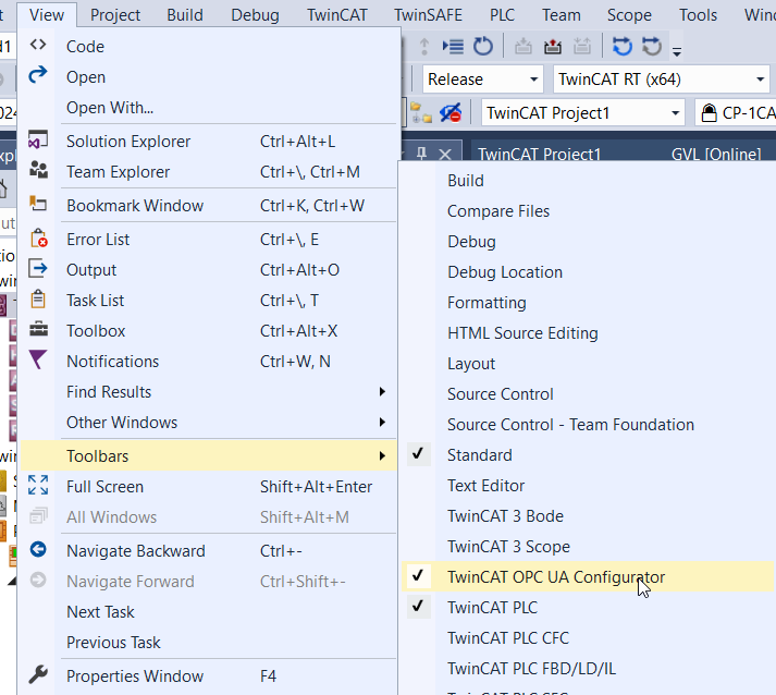
Go to View>Toolbars>TwinCAT OPC UA Configurator to enable the configurator.
Add Device Type
Data Access>Add Device Type to add the Data Access function.
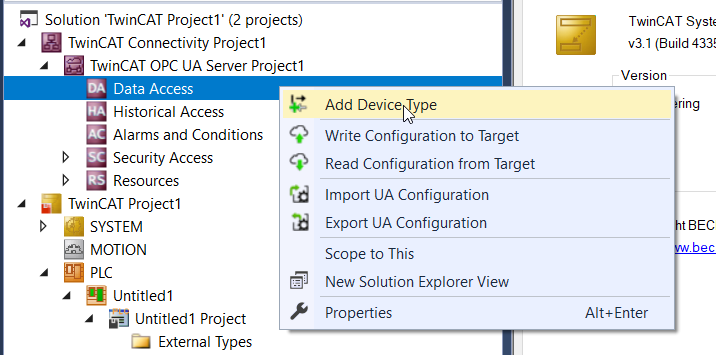
Configure the ADS Port to 851 and set up the AMS Net ID>Create.
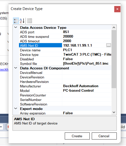
Data Access object is created.

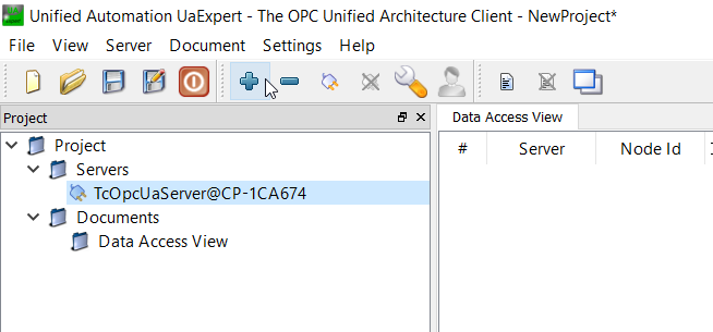
Connect
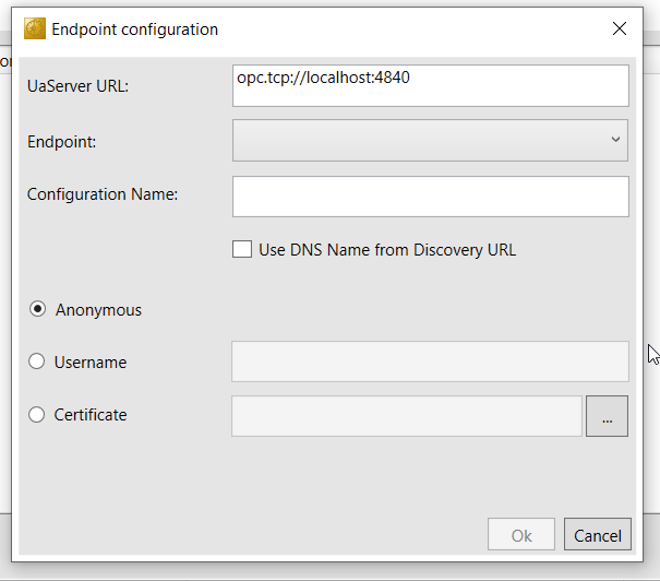
Select the Edit Server List Drop-list and create your OPC UA Server Connection.

Server Configuration Screen is shown and press Add Server to insert a Server.

Enter the UaServer link as opc.tcp://localhost:4840, choose the Endpoint and ok.
Result
Now we can use UaExpert to check the connectivity of the TwinCAT OPC UA Server.
The connection is ok.
{attribute ‘OPC.UA.DA’ }?
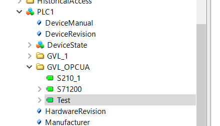
The attribute ‘OPC.UA.DA’ in the TwinCAT project can be set to 1 and 2. Simply put,1=Every node in the struct is visible. 2=Hide all Nodes in the struct. Let’s look at an actual example.
| {attribute ‘qualified_only’} VAR_GLOBAL {attribute ‘OPC.UA.DA’ := ‘2’} {attribute ‘OPC.UA.DA.StructuredType’ := ‘1’} {attribute ‘OPC.UA.DA.Description’ := ‘Complex (structured) type ‘} S210_1 :DUT_OPCUA_S210; {attribute ‘OPC.UA.DA’ := ‘1’} {attribute ‘OPC.UA.DA.StructuredType’ := ‘1’} S71200 :DUT_OPCUA_S71200_OPCUA; {attribute ‘OPC.UA.DA’ := ‘1’} {attribute ‘OPC.UA.DA.StructuredType’ := ‘1’} {attribute ‘OPC.UA.DA.Description’ := ‘Complex (structured) type ‘} Test:DUT_OPCUA_S71200_OPCUA; END_VAR |
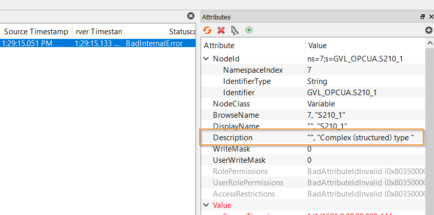
S210_1 has {attribute ‘OPC.UA.DA’ =2} and S71200 has {attribute ‘OPC.UA.DA’ =1}. S210_1 and S71200 are also structures, but when viewed from UAExpert, variables such as CPUStatus can be seen in S71200 variables, but S210_1 is only for its Node.

{attribute ‘OPC.UA.DA.Description’ := ‘Complex (structured) type ‘}
This Attribute allows you to add a Description to a Node.
Implementation-2
Next, I will try to access the OPC UA Server of Beckhoff TF6100 via OPC-UA from Node-Red built in Phoenix Contact EPC1522.
Node-Red Side
Because the TwinCAT side is ready, let’s do the Node-Red side next.
OPCUA Node Version
This is my Node-red-contrib-opcua Version, and please use the latest version.

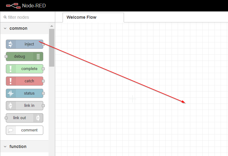
Add OPCUA Node
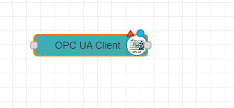
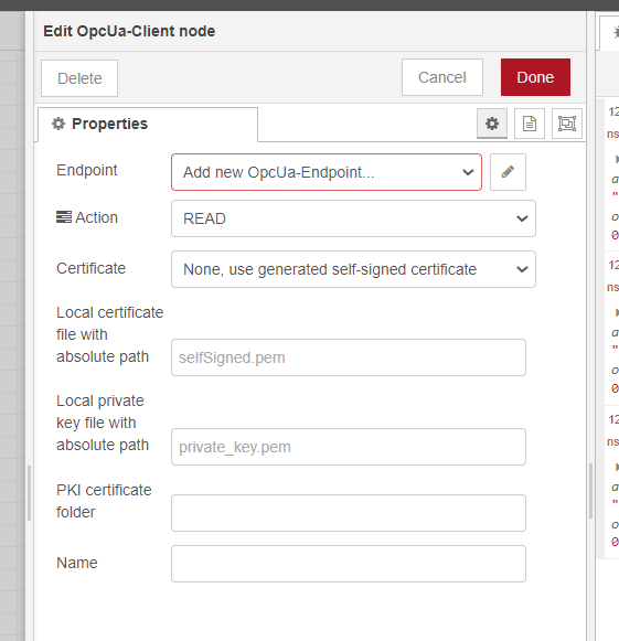
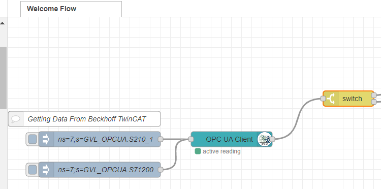
Insert the OpcUa-Client node into your flow.
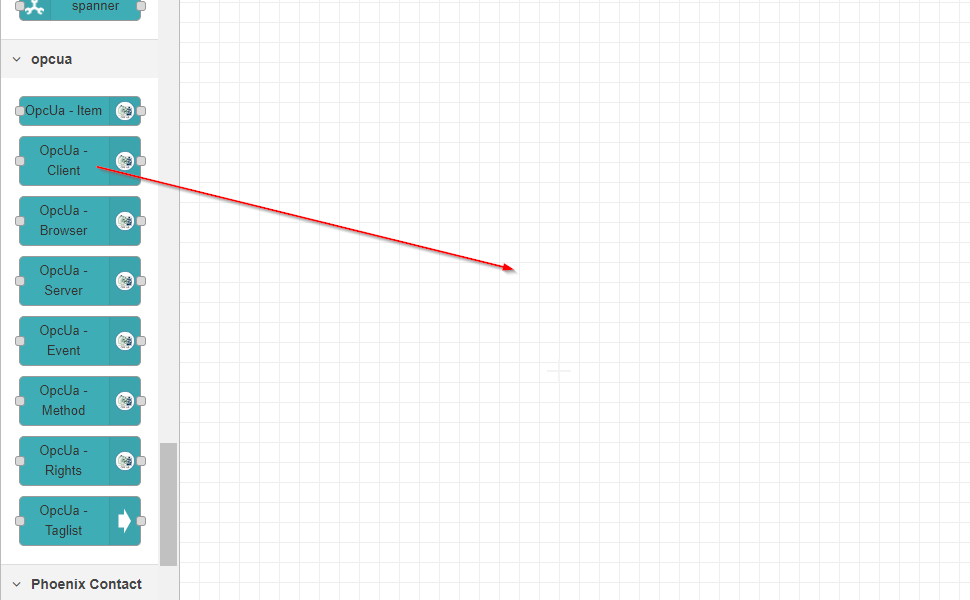
Node is inserted please double click it to configure the OPC UA Client.
Configure the Endpoint with your Beckhoff OPC UA server,Set the Action as Read, and None as the Certificate options.
Add Inject Node
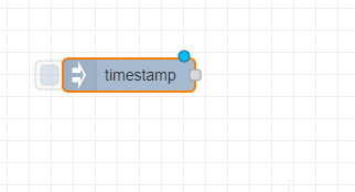
insert an Inject Node in your flow.
Timestamp Node is inserted.
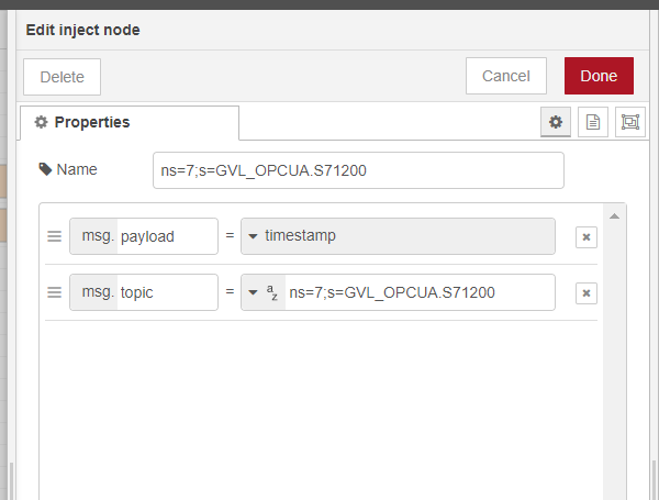
Double that Node and Configure the message.

msg.topic is the Node ID that you would like to access to OPC UA Server and you can get this information from UaExpert software.
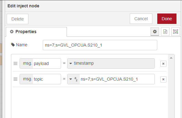
S71200 and S210 Nodes are added.
Finally connect this timestamp to the OPC UA Client Node.

Add Switch
Insert a Switch Node into your flow to create a branch control.

Switch nodes are added.

Double Click the switch node to configure it.
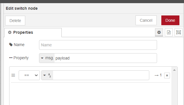
Condition 1 will be true while the msg.topic is equal to S210.
Condition 2 will be true while the msg.topic is equal to S71200.

Connection the Output of OPC UA Client node to the input of Switch node.
Add Function
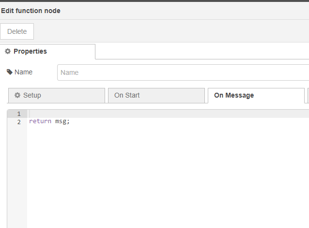
Add the Function Node into your Flow.

Let’s double click the Function Node and add some scripts.
Node1
Here is the script while msg.payload is equal to S210.The OPCUA Client accesses the OPC UA Server and decodes data from the received Extension Object.
| global.set(“S210”,msg.payload); msg.payload = [ { measurement: “Siemens-S210”, fields: { error :msg.payload.status.error | 0, errorStop :msg.payload.status.errorStop | 0, softLimitMinExceeded :msg.payload.status.softLimitMinExceeded| 0, softLimitMaxExceeded :msg.payload.status.softLimitMaxExceeded| 0, errorID :msg.payload.status.errorID }, tags:{ location:”Error” }, timestamp: new Date() }, { measurement: “Siemens-S210”, fields: { motionState :msg.payload.status.motionState , disabled :msg.payload.status.disabled | 0, stopping :msg.payload.status.stopping | 0, hasJob :msg.payload.status.hasJob | 0, inPositionArea :msg.payload.status.inPositionArea | 0, inTargetPosition :msg.payload.status.inTargetPosition | 0, homed :msg.payload.status.homed | 0, accelerating :msg.payload.status.accelerating | 0, decelerating :msg.payload.status.decelerating | 0, operational :msg.payload.status.operational | 0, moving :msg.payload.status.moving | 0, notMoving :msg.payload.status.notMoving | 0, actualStation :msg.payload.actualStation, actualVelocity :msg.payload.actualVelocity, actualPosition :msg.payload.actualPosition, }, tags:{ location:”Status” }, timestamp: new Date() }, ]; return msg; |
Node2
Here is the script while msg.payload is equal to S71200.The OPCUA Client accesses the OPC UA Server and decodes data from the received Extension Object.
| global.set(“S71200”,msg.payload); msg.payload = [ { measurement: “Siemens-S71200”, Commands: { reset :msg.payload.operCommands.reset | 0, }, tags:{ location:”Commands” }, timestamp: new Date() }, { measurement: “Siemens-S71200”, fields: { timeSettingError :msg.payload.ESTOP.timeSettingError | 0, ackNotEnable :msg.payload.ESTOP.ackNotEnable | 0, ackMissingEnable :msg.payload.ESTOP.ackMissingEnable | 0, ackRequired :msg.payload.ESTOP.ackRequired | 0, state :msg.payload.ESTOP.state, }, tags:{ location:”ESTOP” }, timestamp: new Date() }, { measurement: “Siemens-S71200”, fields: { STO :msg.payload.cpUStatus.STO | 0, SS1 :msg.payload.cpUStatus.SS1 | 0, SLS :msg.payload.cpUStatus.SLS | 0, SLT :msg.payload.cpUStatus.SLT | 0, internalEventAcknowledge:msg.payload.cpUStatus.internalEventAcknowledge | 0, run :msg.payload.cpUStatus.run | 0, ERROR :msg.payload.cpUStatus.ERROR | 0, maint :msg.payload.cpUStatus.maint | 0, }, tags:{ location:”CPUStatus” }, timestamp: new Date() }, ]; return msg; |
Connect the output of Switch to trigger the Function Nodes.

Add Debug
Finally we can insert the Debut Node info into your Flow and confirm the payload.
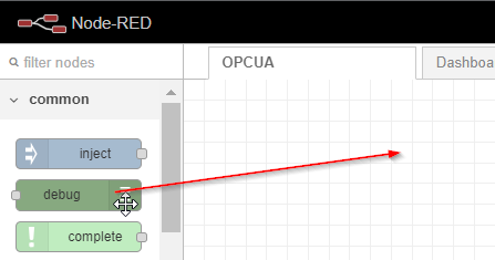
please insert the output of Function node to the Debug Node.

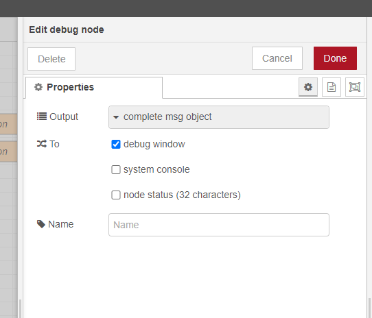
Double Click the Debug Node and configure the Output mode as “Complete msg object”.
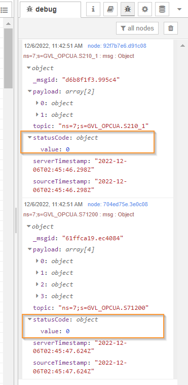
Result
Done!Node-Red can access the TwinCAT OPC UA Server.

Node exists while Status Code=0.
Implementation-3
In this Implementation, I will create a Dashboard for Visualization.
Install Node
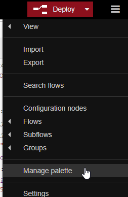
Click the Manage Palette button.
Search Node-red-dashboard and install this node.

Press ”Install” to continue.

Please wait a minute..

And we can confirm the installation process from the Event log function.
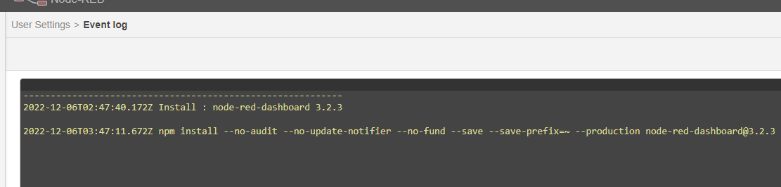
Done!
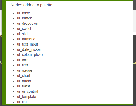
Dashboard is inserted in your Node-Red.

Add Flow
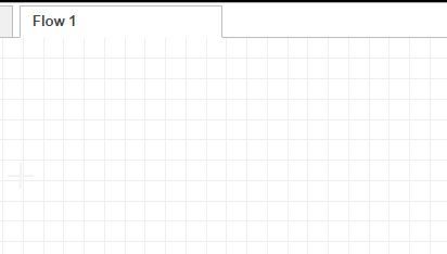
Click the +Button to create a new Flow.

Flow1 is created in your project.
Double Click the Flow tab to modify your flow name.

Add Flow Variables
A global variable is defined to transfer the OPC UA data in implementation -2 and we will define a Flow variable again here.

Define a Flow variable like this transferred from Global Variable.
| flow.S71200=global.get(“S71200”); flow.S210=global.get(“S210”); msg.S71200=flow.S71200; msg.S210=flow.S210; return msg; |
Add Dashboard
Insert the Dashboard Node in your Flow.

Result
Done! Dashboard is shown also.

You can confirm the Operation from this Link.
Implementation-4
Finally, InfluxDB will also be integrated into our System.
InfluxDB Side
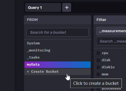
Add Bucket
Access InfluxDB and add a new Bucket with Create Bucket.
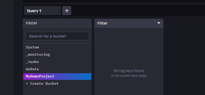
Enter Bucket name > Set retention period of Data > Proceed with Create.

A Bucket that named with MyDemoProject is inserted.
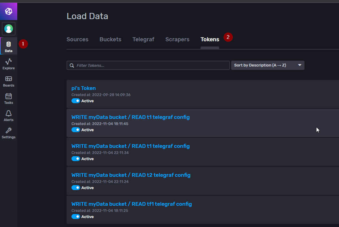
Configure API Tokens
Next we need to generate an API KEY to access the InfluxDB API.
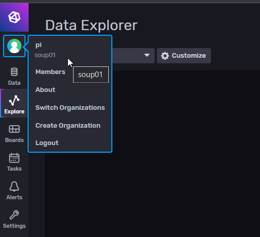
Open Data>Tokens.
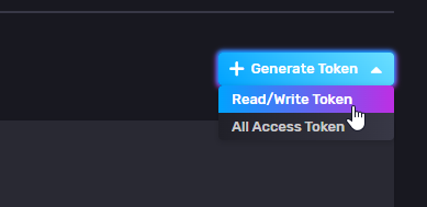
Click “Generate Token” on the right to generate Token.

Choose ”Read/Write Token”.
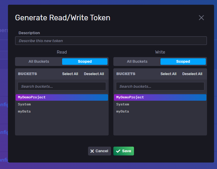
Set the range that API KEY can read and write and save it. I will also configure this API Key limitless to use only the “MyDemoProject”.
Done! An API KEY has been generated.
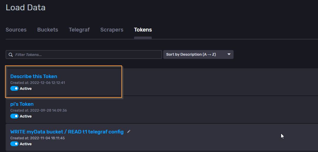
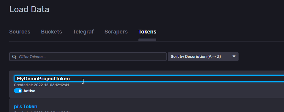
Next, click the pencil icon and change the API KEY name.

Done!
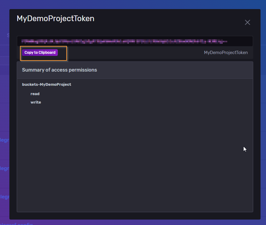
Next, double-click API KEY and save the API KEY with the Copy to Clipboard button.
Add Dashbord
Create a dashboard for display.
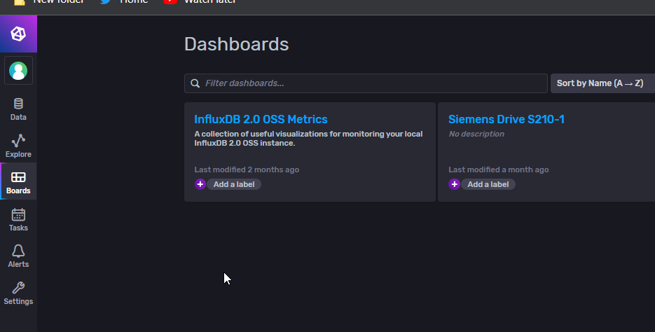
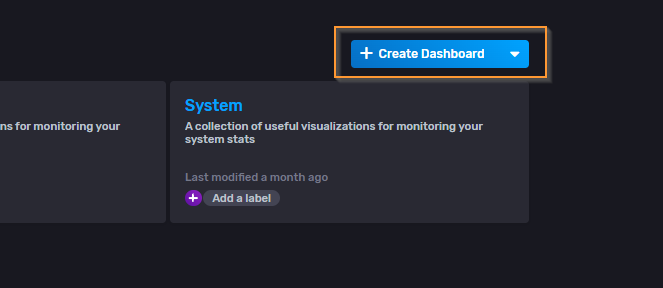
Create a Dashboard with Create Dashboard on the right.
Choose “New Dashboard”.
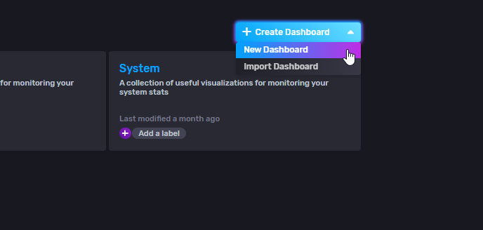
Dashboard is created.

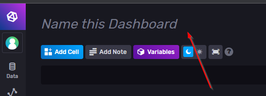
Rename it
Let’s rename Dashboard to something easy to change.
Add Cell
Add display items with the Add Cell button.

It will change to the query creation screen.

Add Query
Select data from MyDemoProject Bucket.

I will take the current Speed/Position/Station for example.

Next, send the query with the Submit button.

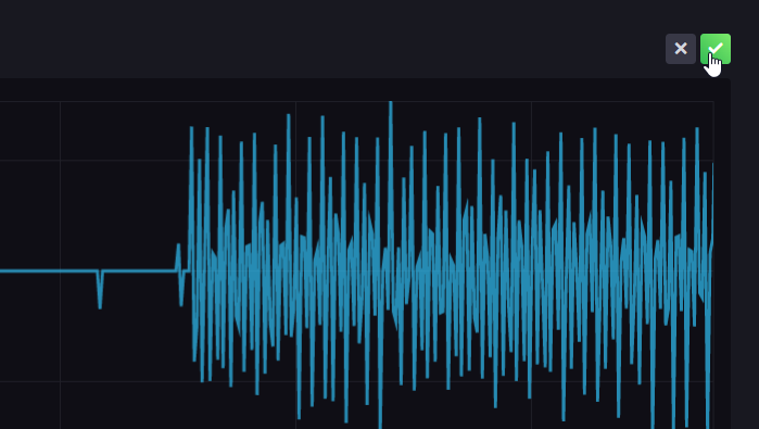
OK, we got the data!

Finally, save the query with the green Check button.
Node-Red Side
Add Influxdb node
Add Influxdb in Node to Flow.

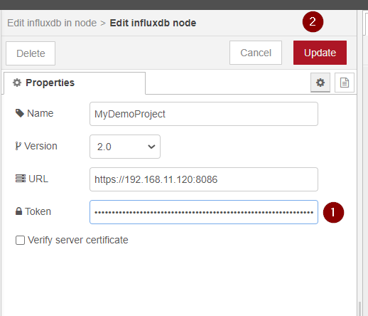
Configure your Organization and Bucket to match your InfluxDB settings.

Next, set the connection information for InfluxDB Server.
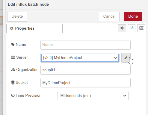
Enter your Influxdb Ip address:8086 in the URL field and paste the AP Key in the Token field.
Finally we need to press update to save the settings.
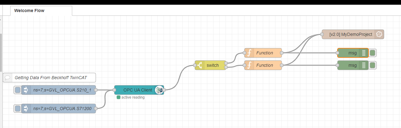
Connect these two functions to the influxDB Node.
Result

And you can confirm the result in this video also.
Source Code
Please download the source project from this link:
https://github.com/soup01Threes/TwinCAT3/blob/main/TwinCAT%20S210-part6.tnzip