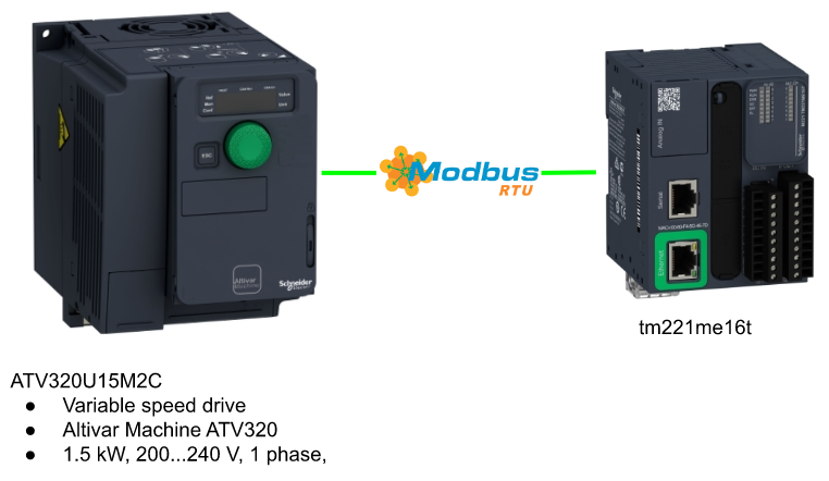
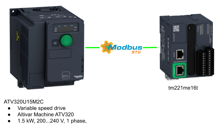
In the last tutorial, we use the DI1/DI2/AI1 to control the Schneider ATV320U15M2C inverter with Schneider CPU TM221ME16T. Now I will show you how to use ModbusRTU and Drv Object to control this drive.
Let’s Start!
Reference Link
Drv Object?
The main Topic in this tutorial is Drv Objects. Drv Object(Drive Objects) is a series of Drive Function blocks that allow drive devices such as Altivar Speed Drive to be controlled from an M221 CPU easily.You can image it as Technology Object in Siemens/AXIS_REF in Beckhoff..etc.
By using Drive Object, you can:
- Control the speed of a motor with ATV drive easily
- The data is updated continuously
- Monitor the status of your Drive and Motor easily
- Error Detection of your Drive easily
The configuration can be done by EcoStruxure Machine Expert and no extended software is needed,you can find the instructions step by step in my tutorial.
Here are the Function Block can save your life to easy control the ATV Drives:
- MC_Power_ATV
- MC_Jog_ATV
- MC_MoveVel_ATV
- MC_Stop_ATV
- MC_ReadStatus_ATV
- MC_ReadMotionState_ATV
- MC_Reset_ATV
Function Block
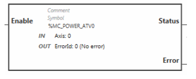
MC_Power_ATV: Enable/Disable Power Stage
We can use this Function Block to Enable/Disable the drive power(you can image it as MC_Power in PLC Open library)
- The Output parameter “Status” is set to 1 while the power stage is enabled.
- The Power stage will be disabled while a falling edge of the Input parameter “Enable” is detected – Then the Output “Status” is set to 0.
- A Timeout Error is generated while the CPU can not reach the Internal status register of ETA/ATV drives – and the timeout is based on the channel cycle time multiplied by 4 or 10 seconds.
- The Output parameters “Error” is set to 1 if any errors are detected while the function block is executing.
- ATV will be disabled with the Shutdown command(CMD=16#0006)
- ETA will be disabled with the Shutdown command(CMD=16#xx21)
- You need a successful execution of MC_Reset_ATV Function block to resume the power stage.
VAR_INPUT
| Variable | Type | Description |
| Enable | 1=Enable the power stage0=Disable the power stage | |
| Axis | %MC_POWER_ATVi.AXISi=0..15 | The identifier of your Drive(From %DRV0 to %DRV15) |
VAR_OUTPUT
| Variable | Type | Description |
| Status | %MC_POWER_ATVi.Statusi=0..15 | 1=Power stage is enabled0=Power stage is disabled |
| Error | %MC_POWER_ATVi.Errori=0..15 | 1=Error is detected while the function block is executing. |
| ErrorId | %MC_POWER_ATVi.ErrorIdi=0..15 | The Error information if value >1Range:0..65535 |
MC_ReadStatus_ATV: Read Device Status
We can use this Function Block to read the status of our ATV Drives.

VAR_INPUT
| Variable | Type | Description |
| Enable | 1=Enable the Function Block | |
| Axis | %MC_READSTATUS_ATVi.AXISi=0..15 | The identifier of your Drive(From %DRV0 to %DRV15) |
VAR_OUTPUT
| Variable | Type | Description |
| Valid | %MC_READSTATUS_ATVi.Validi=0..15 | 1=Function Block is running without errors. |
| ErrorStop | %MC_READSTATUS_ATVi.ErrorStopi=0..15 | 1=Drive is in an Error Status. |
| Disabled | %MC_READSTATUS_ATVi.Disabledi=0..15 | 1=Drive is not in an operational status, but no error |
| Stopping | %MC_READSTATUS_ATVi.Stoppingi=0..15 | 1=MC_STOP_ATV is running or Drive is being stopped. |
| StandStill | %MC_READSTATUS_ATVi.StandStilli=0..15 | 1=Drive is in an operational status,but the speed=0 |
| ContMotion | %MC_READSTATUS_ATVi.ContMotioni=0..15 | 1=Drive is in an operational status,but the speed is <>0 |
| Error | %MC_READSTATUS_ATVi.Errori=0..15 | 1=Error is detected while the function block is executing. |
| ErrorId | %MC_READSTATUS_ATVi.ErrorIdi=0..15 | The Error information if value >1Range:0..65535 |
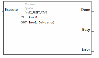
MC_Reset_ATV: Acknowledge and Reset Error
We can use this Function Block to Reset our ATV Drives.
VAR_INPUT
| Variable | Type | Description |
| Enable | 1=Enable the Function Block | |
| Axis | %MC_Reset_ATVi.AXISi=0..15 | The identifier of your Drive(From %DRV0 to %DRV15) |
VAR_OUTPUT
| Variable | Type | Description |
| Done | %MC_Reset_ATVi.Donei=0..15 | 1=Function Block is executed without any error |
| Busy | %MC_Reset_ATVi.Busyi=0..15 | 1=Function Block is executing |
| Error | %MC_Reset_ATVi.Errori=0..15 | 1=Error is detected while the function block is executing. |
| ErrorId | %MC_Reset_ATVi.ErrorIdi=0..15 | The Error information if value >1Range:0..65535 |
MC_Jog_ATV: Start Jog Mode
We can use this function to operate the drive as Jog Mode – The drive will move forwards or backwards at the specified velocity based on the commands.(You can image it as MC_Jog in the PLC open library)
- The Busy Output will reset to 0, CmdAborted Output will set to 1 if the function blocks “MC_MoveVel_ATV” or “MC_Stop_ATV” is enabled(Busy=1).
- The velocity command can be modified only on a detection of falling/rising edge of the Forward or Backward inputs – While your Jog operation is in progress.
- You can reset the Forward or Backward to 0 if an Error or CmdAborted is set to 1 to restart the movement.
- IF Forward and Backward commands are both set to 1,Jog movement will stop and Busy is set to 1.
- If Forward and Backward commands are both set to 0, Jog movement will stop and Done is set to 1 with One Cycle Only.

VAR_INPUT
| Variable | Type | Description |
| Forward | 1=operate the drive as forward. | |
| Backward | 1=operate the drive as backward. | |
| Vel | %MC_JOG_ATVi.VELi=0..15 | The velocity for the jog operation in rpm.(-32768..32768) |
| Axis | %MC_JOG_ATVi.AXISi=0..15 | The identifier of your Drive(From %DRV0 to %DRV15) |
VAR_OUTPUT
| Variable | Type | Description |
| Done | %MC_JOG_ATVi.Donei=0..15 | 1(One cycle) if Forward and Backward are set to 0 |
| Busy | %MC_JOG_ATVi.Busyi=0..15 | 1=Jog in progress or Forward and Backward are set to 1 |
| CmdAborted | %MC_JOG_ATVi.CmdAbortedi=0..15 | 1=The execution is aborted because of other command |
| Error | %MC_JOG_ATVi.Errori=0..15 | 1=Error is detected while the function block is executing. |
| ErrorId | %MC_JOG_ATVi.ErrorIdi=0..15 | The Error information if value >1Range:0..65535 |
MC_MoveVel_ATV: Move at Specified Velocity
We can use this function to operate the drive with a specified velocity.
- InVel is set to 1 if the drive reaches the target velocity.
- CmdAborted is set to 1 if MC_Jog_ATV or MC_Stop_ATV is enabled while MC_MoveVel_ATV is executing, and the Busy is set to 0.
You need a new rising edge of Execute parameter to re-activate the movement. - Error is set to 1 if MC_Stop_ATV is enabled, but you set the Execute to 1.

VAR_INPUT
| Variable | Type | Description |
| Execute | Start the job by a Rising Edge | |
| ContUpdate | 1=The Speed will continue update | |
| Vel | %MC_MOVEVEL_ATVi.VELi=0..15 | The velocity for the specified velocity operation in rpm.(-32768..32768) |
| Axis | %MC_MOVEVEL_ATVi.AXISi=0..15 | The identifier of your Drive(From %DRV0 to %DRV15) |
VAR_OUTPUT
| Variable | Type | Description |
| InVel | %MC_MOVEVEL_ATVi.InVeli=0..15 | 1=Target Velocity is reached |
| Busy | %MC_MOVEVEL_ATVi.Busyi=0..15 | 1=Function Block is executed, and remains as 1 after InVel=1.0=Function Block is stopped/aborted |
| CmdAborted | %MC_MOVEVEL_ATVi.CmdAbortedi=0..15 | 1=The execution is aborted because of other command |
| Error | %MC_MOVEVEL_ATVi.Errori=0..15 | 1=Error is detected while the function block is executing. |
| ErrorId | %MC_MOVEVEL_ATVi.ErrorIdi=0..15 | The Error information if value >1Range:0..65535 |
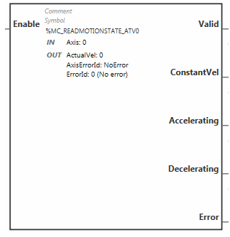
MC_ReadMotionState_ATV: Read Motion State
We can use this function block to read the movement status from the ATV Drive.
VAR_INPUT
| Variable | Type | Description |
| Enable | 1=Enable the Function Block | |
| Axis | %MC_READMOTIONSTATE_ATVi.AXISi=0..15 | The identifier of your Drive(From %DRV0 to %DRV15) |
VAR_OUTPUT
| Variable | Type | Description |
| Valid | %MC_READMOTIONSTATE_ATVi.Validi=0..15 | 1=Function Block is running without errors. |
| ConstantVel | %MC_READMOTIONSTATE_ATVi.ErrorStopi=0..15 | 1=Drive is in Constant velocity movement |
| Accelerating | %MC_READMOTIONSTATE_ATVi.Disabledi=0..15 | 1=Drive is Accelerating |
| Decelerating | %MC_READMOTIONSTATE_ATVi.Stoppingi=0..15 | 1=Drive is Decelerating |
| Error | %MC_READMOTIONSTATE_ATVi.Errori=0..15 | 1=Error is detected while the function block is executing. |
| ActualVel | %MC_READMOTIONSTATE_ATVi.ContMotioni=0..15 | Velocity returned from your ATV drive |
| AxisErrorId | %MC_READMOTIONSTATE_ATVi.Errori=0..15 | Axis Error Identifier if value >1 |
| ErrorId | %MC_READMOTIONSTATE_ATVi.ErrorIdi=0..15 | The Error information if value >1Range:0..65535 |
MC_Stop_ATV: Stop Movement
We can use this Function block to stop the movement of your ATV drive.For the Stop parameters – deceleration,acceleration,etc.. are all referenced from the Configuration of the drive.
- The Operation is started by a rising edge on the Execute Input parameters.
- Other Function Block’s Execute input (For Example,MC_JOG_ATV..)will be ignored until Done=1.
- Other Function Block will end in an error, While the MC_STOP_ATV ‘s busy=1.
- This Stop operation can be only interrupted by :
- disabling the Power stage
- Error occurs
- ATV Not Run error
- Communication error
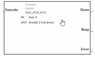
VAR_INPUT
| Variable | Type | Description |
| Enable | 1=Enable the Function Block | |
| Axis | %MC_STOP_ATVi.AXISi=0..15 | The identifier of your Drive(From %DRV0 to %DRV15) |
VAR_OUTPUT
| Variable | Type | Description |
| Done | %MC_STOP_ATVi.Donei=0..15 | 1=Function Block is executed without any error |
| Busy | %MC_STOP_ATVi.Busyi=0..15 | 1=Function Block is executing |
| Error | %MC_STOP_ATVi.Errori=0..15 | 1=Error is detected while the function block is executing. |
| ErrorId | %MC_STOP_ATVi.ErrorIdi=0..15 | The Error information if value >1Range:0..65535 |
Modbus Support Function
Here is the Modus Support Function list of TM221ME16T CPU.

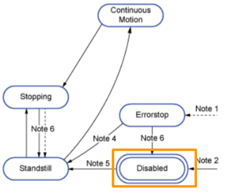
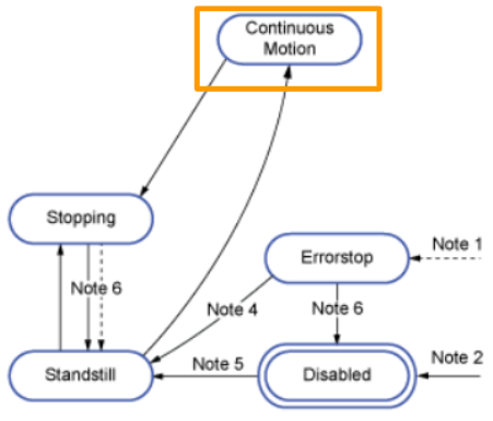
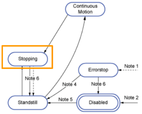
Drive State Diagram
Here is the Drive State Diagram.

Disabled
Disabled is the initial state of your drive and no error, but not operational.
(%MC_POWER_ATV.Status=0 and no error is happening.)
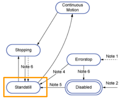
Standstill
Your Drive is in operational state, but Velocity=0.
- From ErrorStop to StandStill
- %MC_Reset_ATV.Done=1 and %MC_Power_ATV.Enable=1,%MC_Power_ATV.Status=1
- From Disabled to StandStill
- %MC_Power_ATV.Enable=1,%MC_Power_ATV.Status=1
ErrorStop
Your drive is in an Error Status and Stopped.
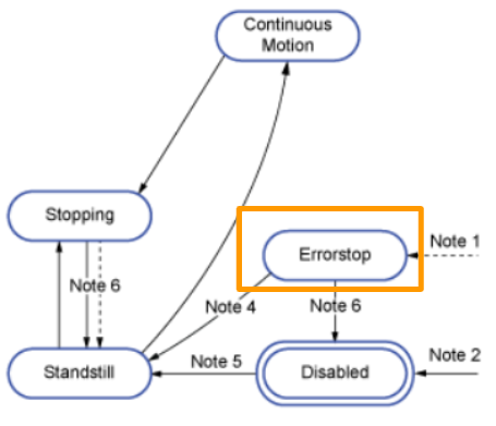
Continuous motion
The drive is in operation and velocity <>0.
Stopping
Your drive is stopping because of MC_STOP_ATV.
Implementation
Now I will show you how to configure ATV320 as a ModbusRTU slave, and TEM221ME16T as A ModbusRTU Master.
Reference Link
ATV320 Side
Modbus Configuration
Firstly, we need to enable the Modbus Communicate Function in our ATV320.
Set Command Channel
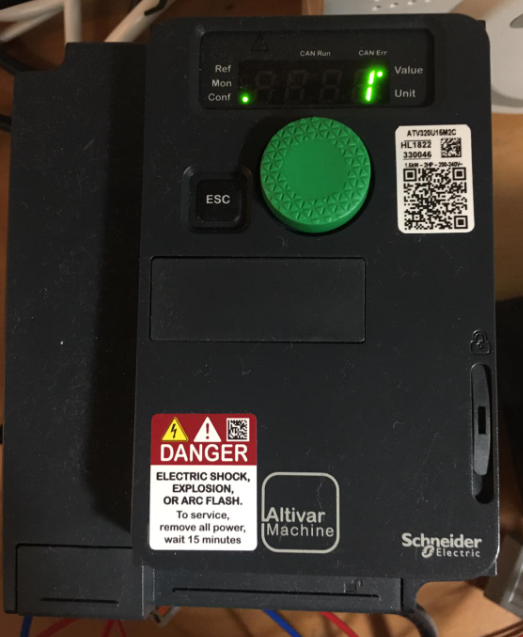
Go to ConF Menu.

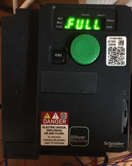
Open the FULL Menu.
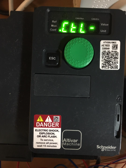
Go to the CTL Menu.
Ope the Fr1 menu.

The default value is AI1 – Did you remember that we operate the drive with the AI1 terminal(from0-10v) in the last tutorial?

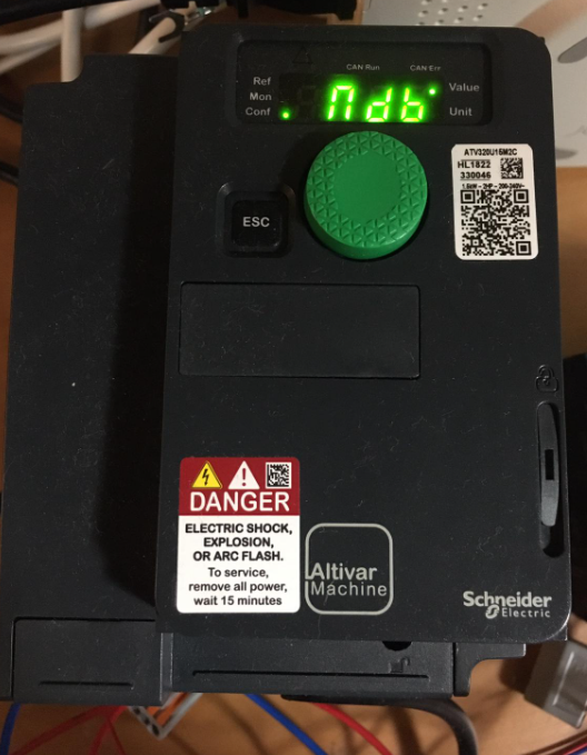
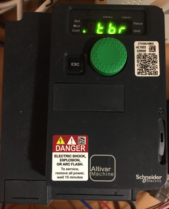
Change the value to “ndb” – it is the modbus option.
Modbus Address
Now we need to configure the communication setting, go to Conf menu.
Enter the FULL menu.
Open the CON Menu.

NdI is the modbus configuration of your ATV320 and open it.

Open the Add options – it is your ATV320’s modbus address setting.
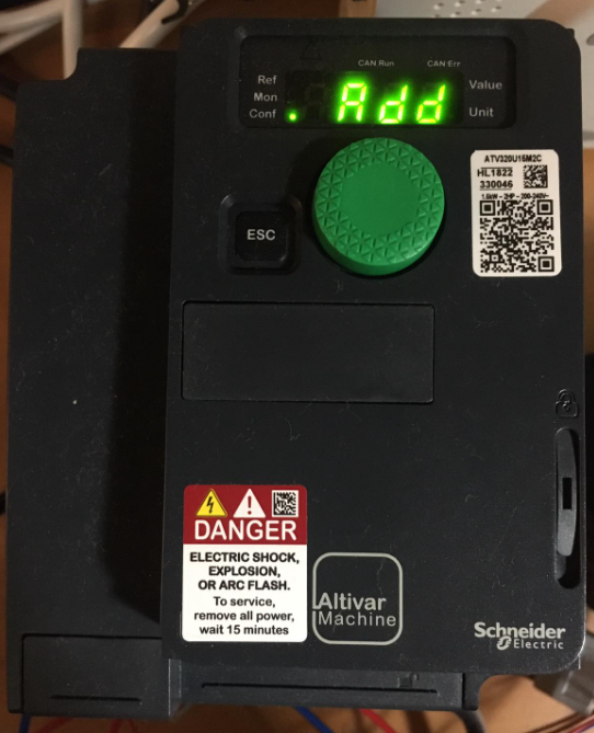
The value=OFF by default.

use the rotate switch to change the address to “1”.
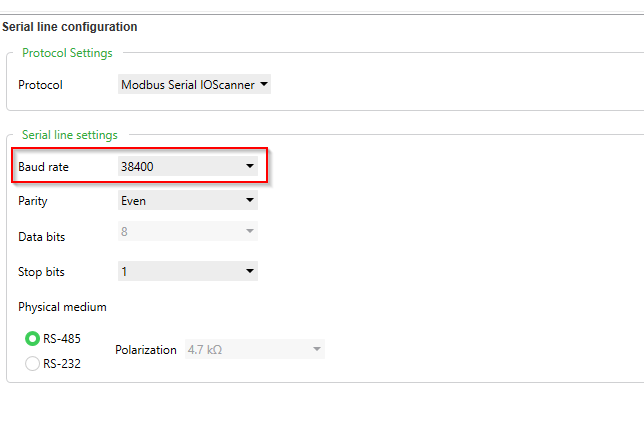
Bandrate
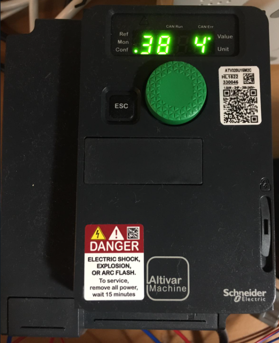
This is the Bandrate Configuration.
Open it and Default=192(19200), I will configure it to 384(38400)
Power Reset
Please power reset your drive to apply all these settings.
TM221ME16T Side
Configure the Modbus
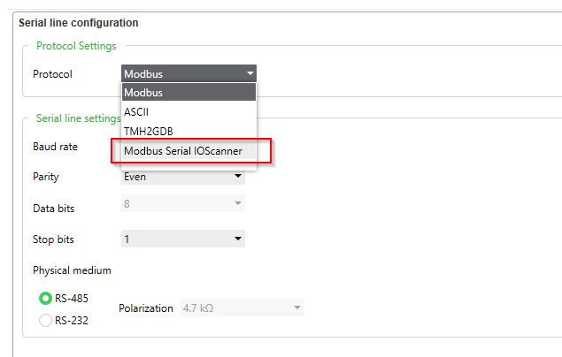
Go to SL1(Serial line)>Modbus.

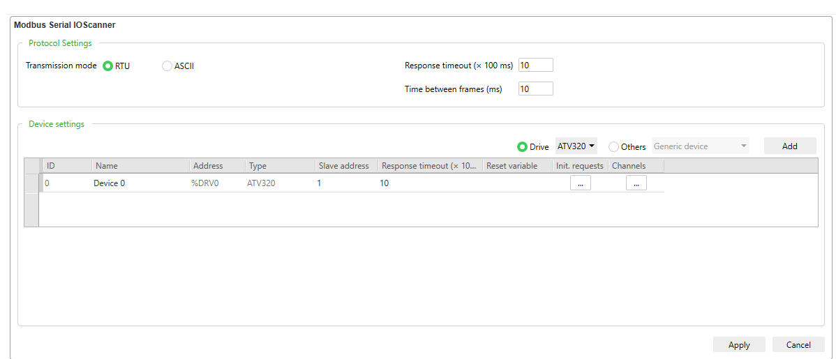
In the Protocol Settings, Select “Modbus Serial IOScanner” as the option.
Please 100% match the setting between your ATV320 and CPU.
In my case, baud rate is changed from 19200 to 38400.
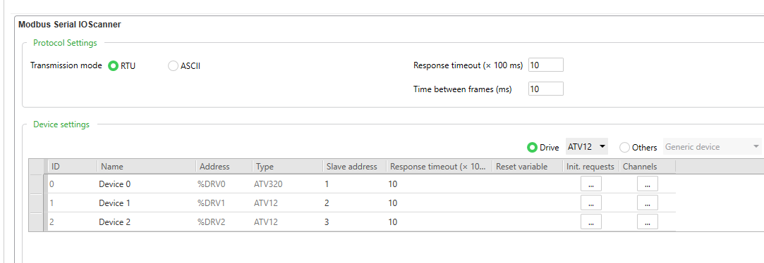
Go to SL1(Serial)>Modbus Serial IOScanner, the Modbus Serial IOScanner configuration screen is shown.
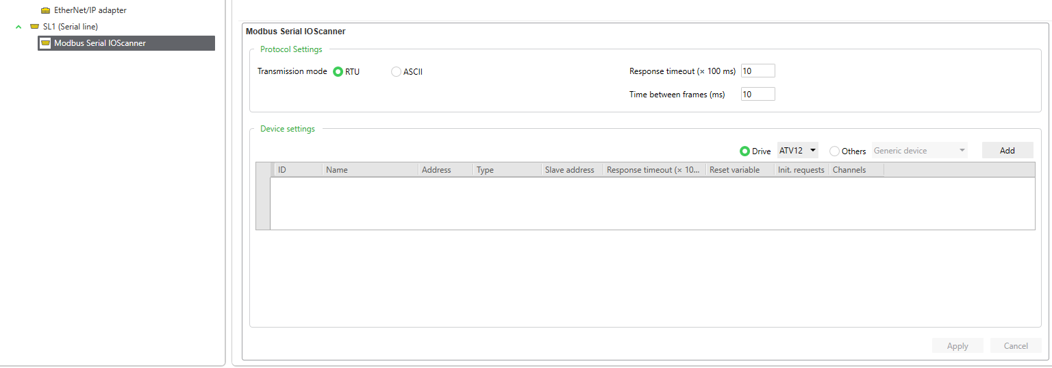
Transmission mode
RTU Mode is used in my tutorial, Select “RTU” as your Transmission mode.

Drive Settings
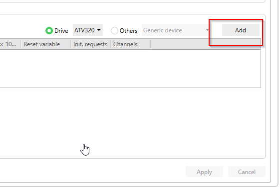
ATV320 is used in this topic, choose “Drive” radio box.

Select ATV320 from the drop-down list.
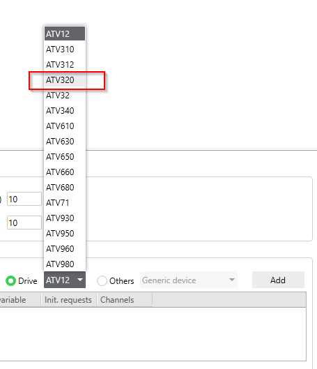
Done.
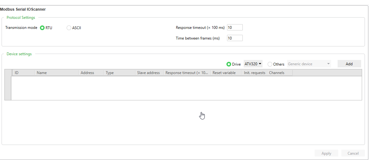
Add Drive
Press the “Add” Button to add this drive in your IOScanner Object.
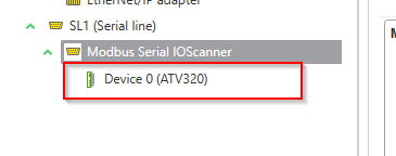
Done!
Device 0 (ATV320) is inserted.
More about this item..
Actually you can imagine the Modbus IOScanner is an Object that uses Modbus Function Code 23 to read/write multiple registers in a request.By the way, you can skip this session.
For Example, Click … button in the Channels Field.
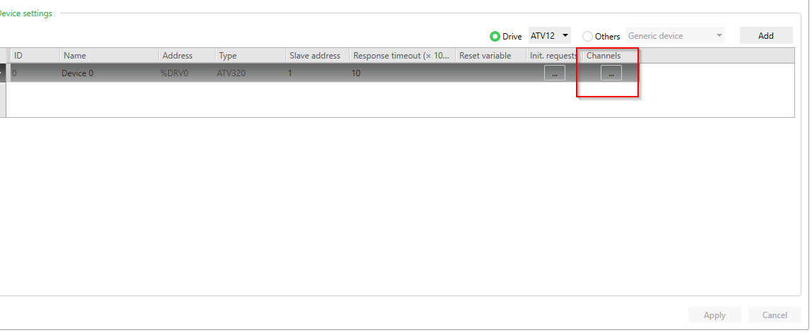
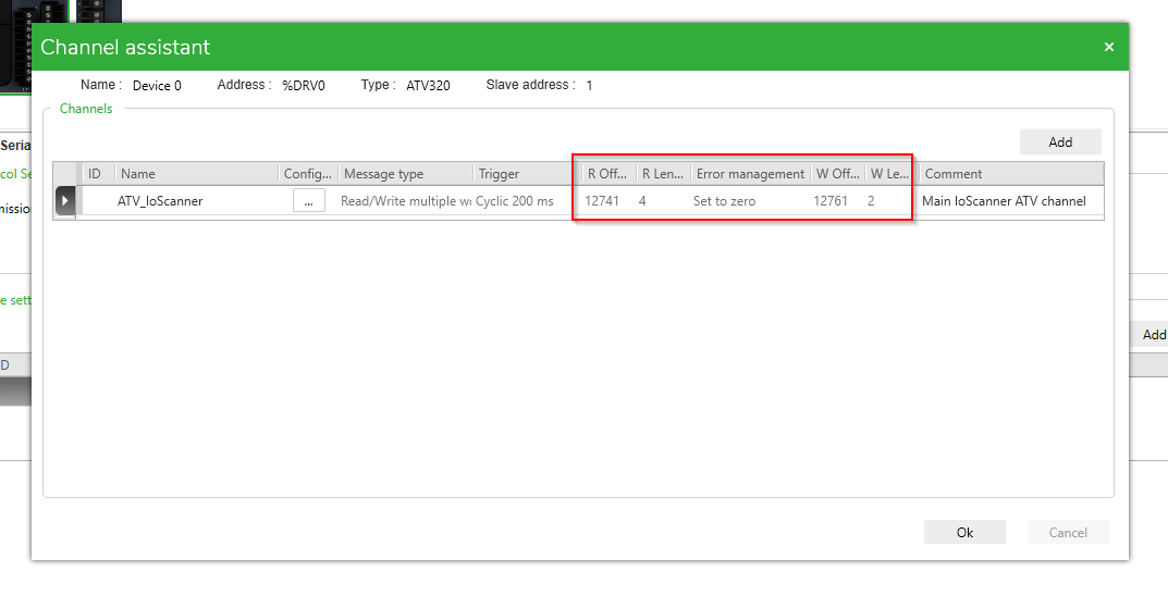
The Channel assistant screen is displayed here and shows you which registers and functions are using this Device.

For the ATV_IoScanner, the message type is 0x17=23 function code.

And The Modbus IOScanner will Read 4 registers from 12741 and write 2 registers from 12761 in one request by using FC23.
Input Register(IOScanner)
Go to Programming Tab>Network objects>Input registers(IOScanner) – you can get more information.

For the Input registers(IOScanner) properties,%IWM100.0.0 to %IWM100.0.3 is shown.
Because 4 Registers are reading from ATV320 , from %IWM100.0.0 to %IWM100.0.3 are those registers.

Here is detail for each Registers:
(12741 and 12742 are defaultly configured as status word and actual speed, I will publish some topics in the future that how you can extend your telegram.[COM Scan in1 val.])
| Variable | Modbus Register | Description |
| %IWM100.0.0 | 12741 | ATV320 Status word |
| %IWM100.0.1 | 12742 | ATV320 Actual Speed |
| %IWM100.0.2 | 12743 | Not Used |
| %IWM100.0.3 | 12744 | Not Used |
Output Register(IOScanner)
Go to Programming Tab>Network objects>Output registers(IOScanner) – you can get more information.
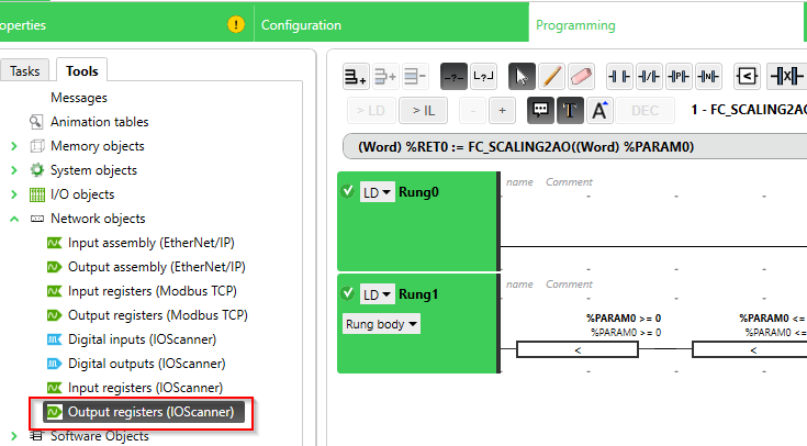
For the Output registers(IOScanner) properties,%QWM100.0.0 to %QWM100.0.1 is shown.
Because 4 Registers are writing to ATV320 , from %QWM100.0.0 to %QWM100.0.1 are those registers.

Here is detail for each Registers:
(12741 and 12742 are defaultly configured as status word and actual speed, I will publish some topics in the future that how you can extend your telegram.[COM Scan out1 val.])
| Variable | Modbus Register | Description |
| %QWM100.0.0 | 12761 | ATV320 Command |
| %QWM100.0.1 | 12762 | ATV320 LFRD(Speed Setpoint) |
FB_SLSTATUS
Add New Function Block
Open the Programming Tab> go to User-defined functions>Add user-defined function block.
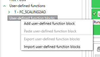
A user-defined function block is inserted in your project.

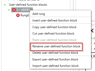
Rename it
Rename your function block with a easy-understand name.
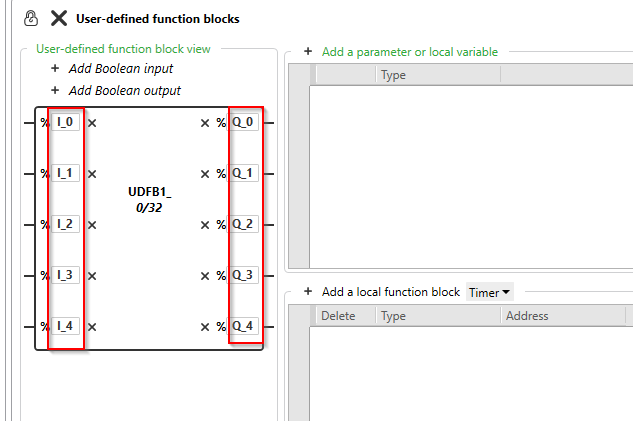
Configure the Input/Output Boolean Data
M221’s Function block may be a little bit different between Siemens,Beckhoff,etc… for the Direct Input/Output parameters, only boolean data can be configured.
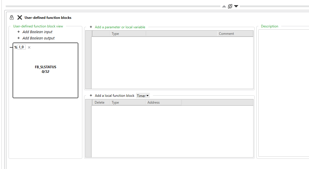

Rename it

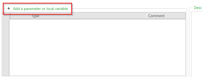
Configure the Parameters

Program
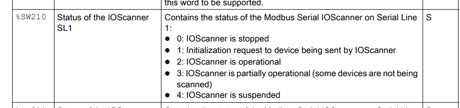
System Word %SW210
How to use Drv Object?
In this part, I will show you how to use Drive Object – open the Programming Tab and click the Drive Objects item.
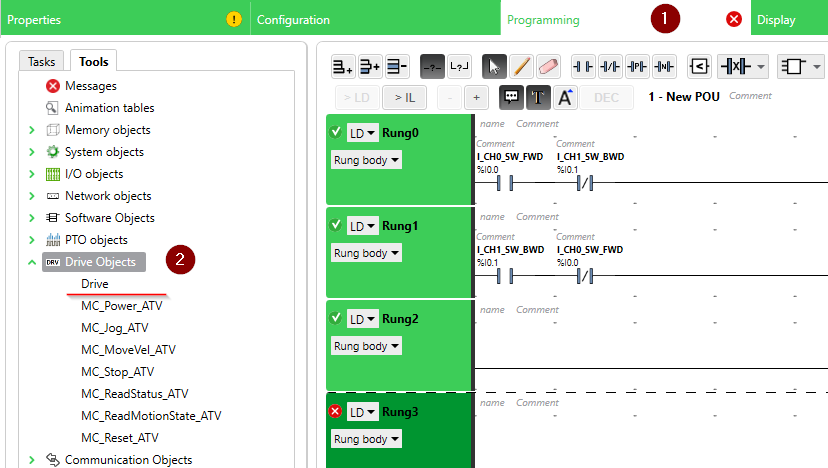
Drive properties are shown and there is only %DRV0 inside.

It is because only one Drive is configured in the Modbus Serial IO Scanner.

Let’s add more drives in your modbus Serial IO Scanner configuration.
%DRV0,%DRV1,%DRV2 is shown now! So – we do not need to care about this properties and these object will automatically add/delete into your project.

How to use MC_XXX Object in a Project?
Then I will show you how to use the MC_XXX Object inside the project.
Check the Mappings
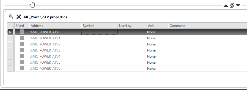
In case if I would like to use MC_Power_ATV in my project, Go to Drive Objects>MC_Power_ATV.

The MC_Power_ATV_ATVi(i=0-15) is shown in the MC_Power_ATV properties.
Call the Object
Open the Programming tab > DRV> choose MC_Power_ATV.
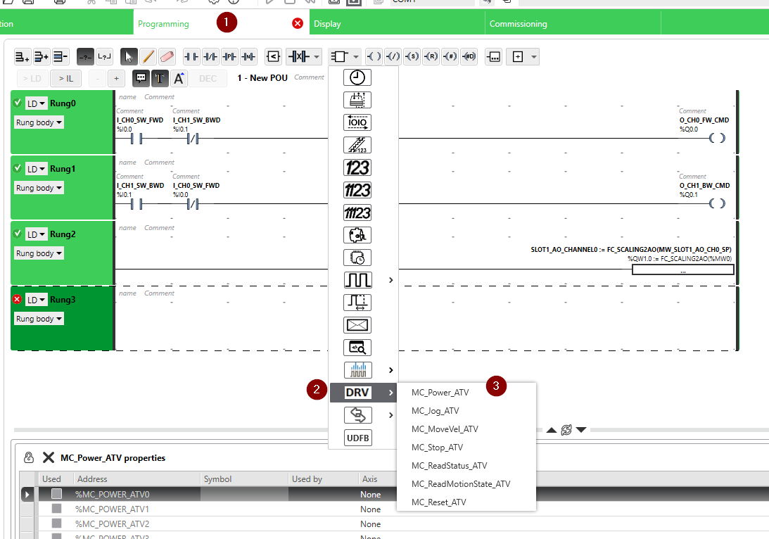
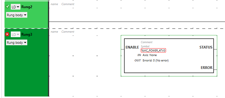
MC_POWER_ATV is inserted into your program and a red mark is marked in the “%MC_POWER_ATV0”, because there is no Drive object assigned with this Block.
Configure the DRV object
Click the %MC_Power_ATV0 Block and a “Configuration” popup is displayed here, you can choose the Drive Object from the Drop-down list.

The operation is like this.
Assign the Input
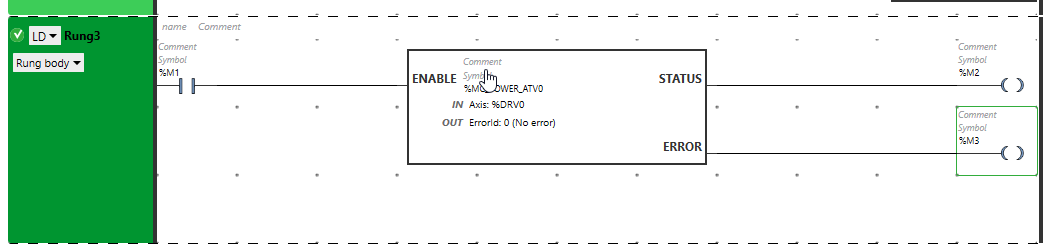
After we assign a NO contact with the ENABLE input, there is no error in your Rung.There is no necessary to assign the output parameter.

Assign the Output
Just assign the output device to to STATUS/ERROR Output.
Assign the WORD/DWORD/FLOAT data
Finally , we can also access this “ErrorId” output parameters to get the Error information of this block.
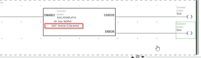
To access this parameter, insert an operation block into your Rung.

An operation block is inserted in the Rung.
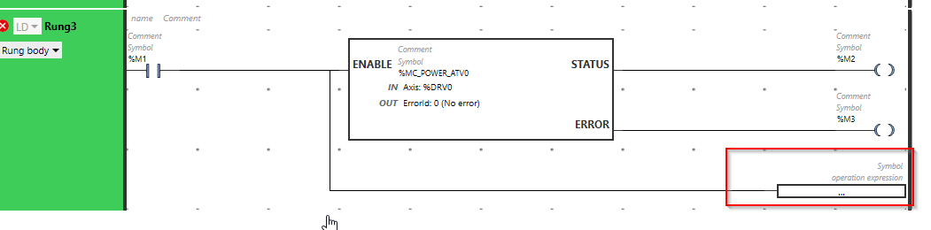
Then you can get the “ErrorId” output with this format:
| %yourDevice:=%Yourobjectname.yourParameters |
In my case, it would be:
| %MW10:=%MC_POWER_ATV0.ERRORID; |

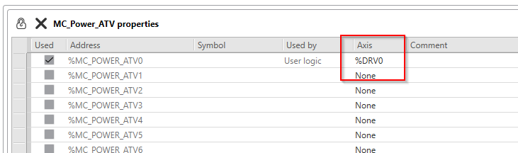
Going back to the MC_Power_ATV properties, %DRIV0 is shown in the “Axis” Field – because we assigned the %DRV0 in the MC_Power_ATV Drive Object.
Program
Now is the time to make the program to control our ATV320 Inverter.
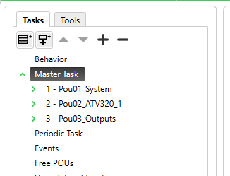
Add Pou in your Master Task
Our project is being complex now and It is better to separate the POUs based on their function.Go to Master Task>Right Click>Add POU.

3 Pous are configured and I will explain step by step what is going on inside.
Configure the Cycle Time
And Also, we can change the cycle time of your Master Task.
The default setting of the Scan mode is “Normal” and I will change it to a Fix Scan with 1ms.

Pou01_System
Pou01_System is a POUs that configures our system flags and Input Signals data.
Rung0 CPU in Run Mode
By using %S12 system bit, we can know the cpu is running if %S12=True.

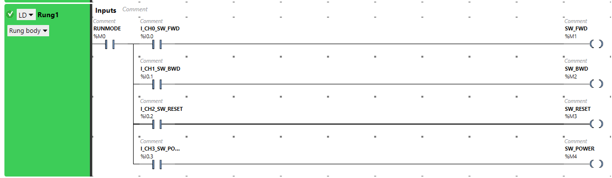
Rung1 Inputs
This program will assign the Input signal that is built in our CPU to the Memory bits.
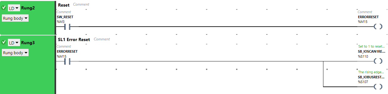
Rung2 Reset/Rung3 SL1 Error Reset
Rung2 is a reset operation and %S110 and %S107 in Rung3 are the system bits that can perform a reset operation of our SL1(Serial Line1) and IO.
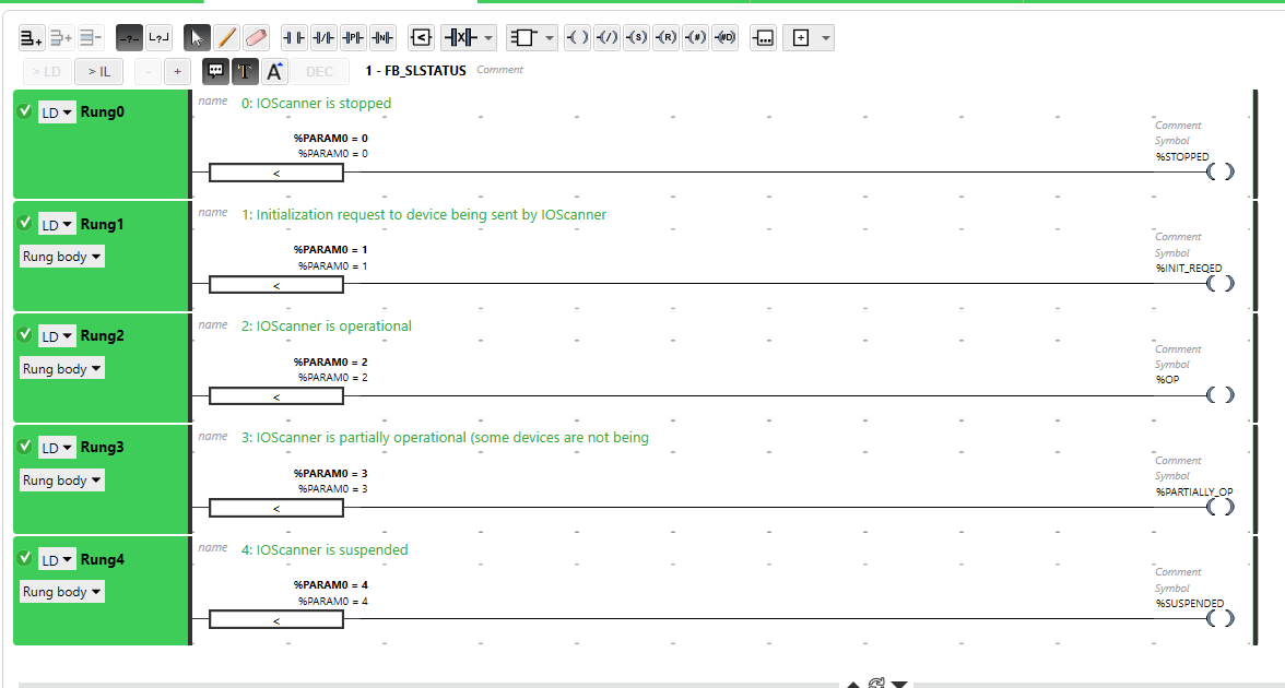
Rung4 Read the SL1 Status
%SW210 is a system word that indicates the current status of your SL1 as a word,and the user-defined function FB_SLSTAUS0 is called to get the current status of the SL1(Serial Line1).

Pou02_ATV320_1
Pou02_ATV320_1 is the main part of our project to control the ATV320 Inverter with the Drive Object.
Rung0 POWER On interlock
Here is an interlock logic – the condition to turn on the power stage of our drive.

Rung1 POWER ON Command
Here is the Power On command – The CPU should be in Run mode with the Interlock condition is true, and the Power On command can be triggered by the Positive edge of our Power ON Push button.
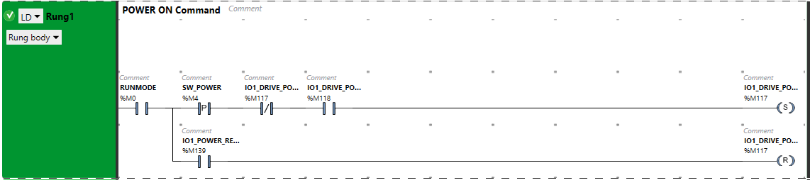
Rung2 MC Power OFF
Here is the Power Off Command, the Power ON Command will set to 0 if any error stop or Interlock is reset to 0.

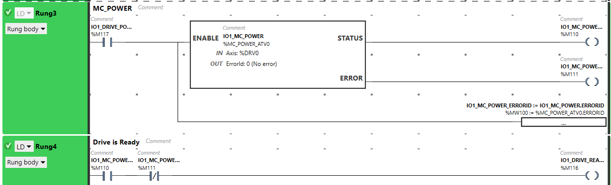
Rung3 MC_POWER/Rung4 Drive is Ready
In Rung3 the Drive Object %MC_POWER_ATVi(i=0-15) is called to control the power stage of our drive, and get the Power stage status from that Drive object.
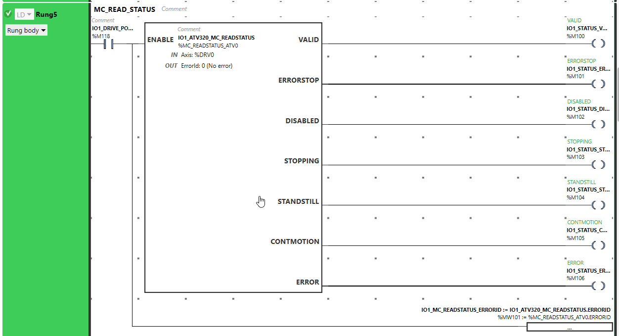
Rung5 MC_READ_STATUS
In Rung5, MC_READSTATUS_ATVi(i=0-15) is used to get the current status of our ATV320.
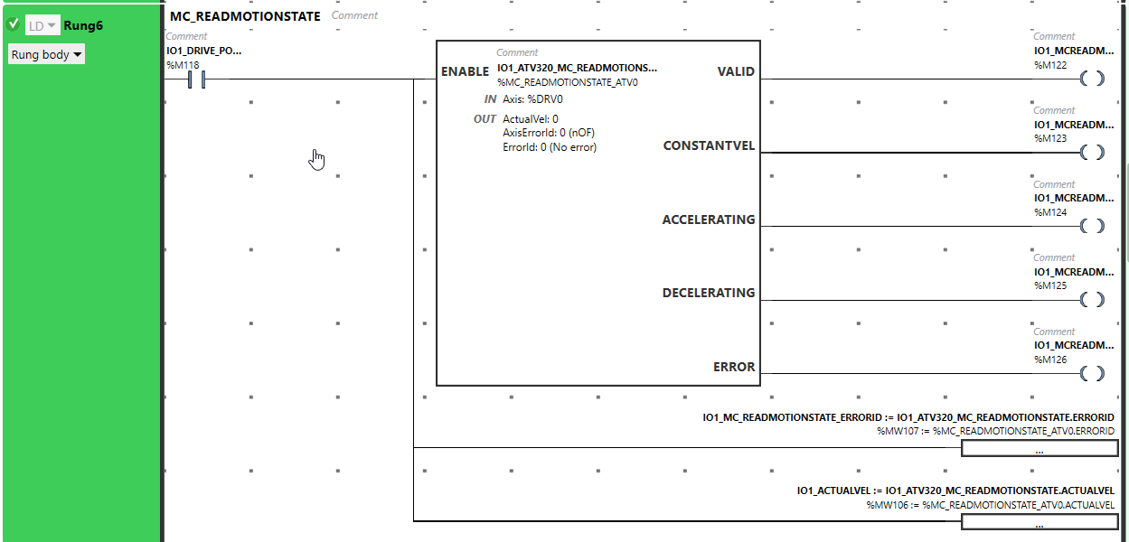
Rung6 MC_READMOTIONSTATE
In Rung6, MC_READMOTIONSTATE_ATVi(i=0-15) is used to get the current motion State of our ATV320.
Rung7 Drive Operation Interlock
In Rung7, an Operation interlock for the Drive moving is created to prevent any moving commands being sent,if the Interlock checking is failed or any error occurs.

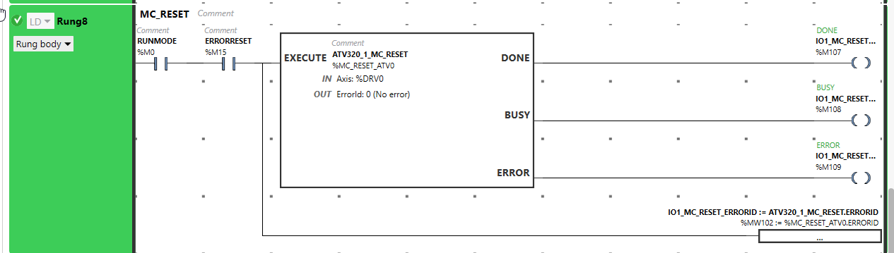
Rung8 MC_RESET
in Rung8, MC_RESET_ATVi(i=0-15) is used to reset our ATV320 drive via the push button.
Rung9 JogFw/JogBw Interlock
In Rung9, the Jog Forward and Backward interlock is created to prevent the Forward and Backward commands being sent at the same time or interlock in a fail state.

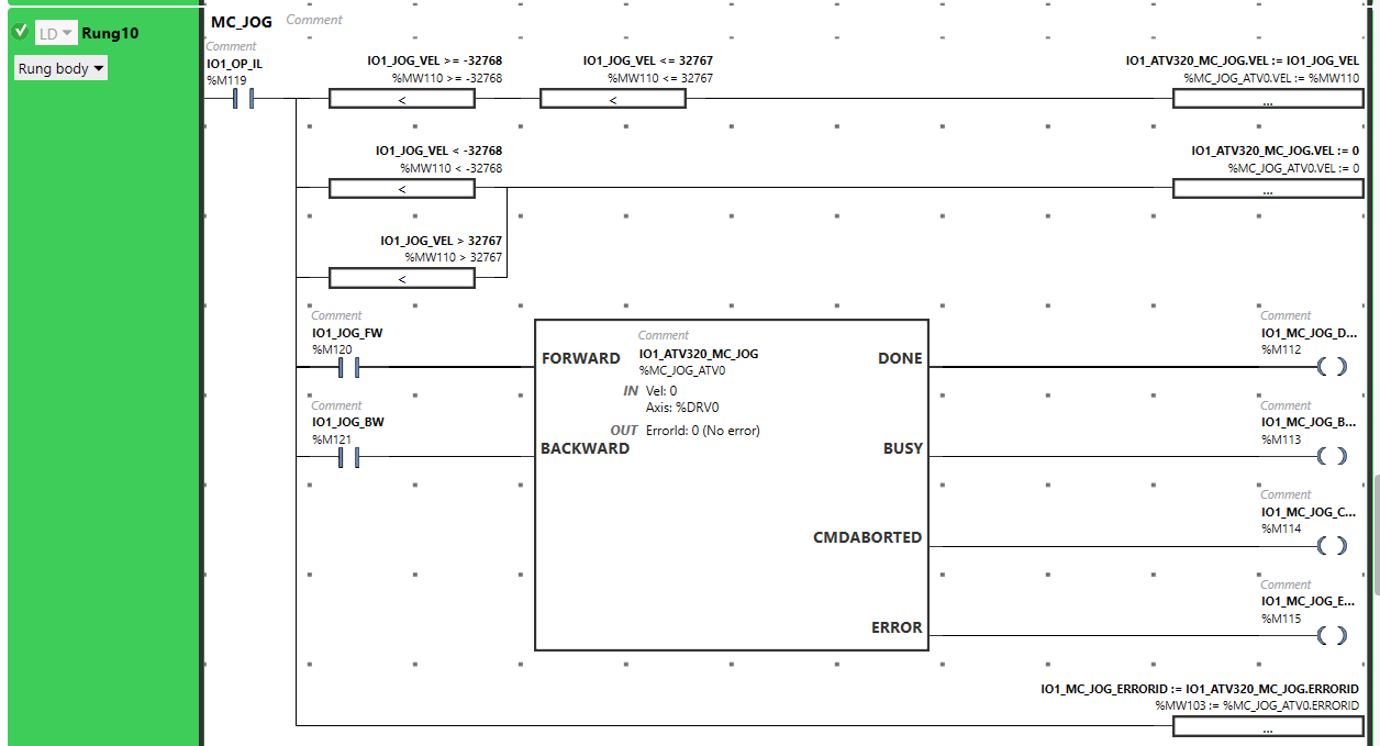
Rung10 MC_JOG
In Rung10, MC_JOG_ATVi(i=0-15) is used to perform a jog operation via 2 push buttons, and a setpoint limit check is performed before passing the speed setpoint to our Drive Object.
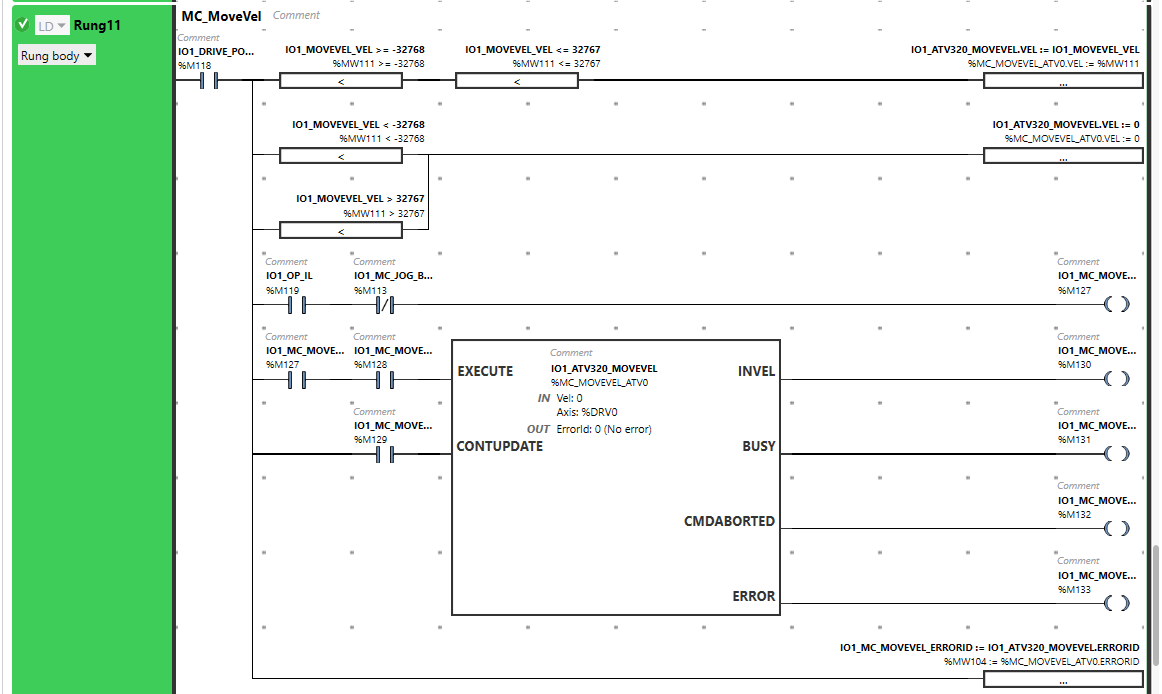
Rung11 MC_MOveVel
In Rung11, MC_JOG_MOVEVELi(i=0-15) is used to perform a constant Velocity operation via the memory bit %M128(because I do not have a push button any more..)
and a setpoint limit check is performed before passing the speed setpoint to our Drive Object.For the interlock program, we will make sure the busy flag of MC_JOG_ATVi(i=0-15) is false(No Jog task is executed).
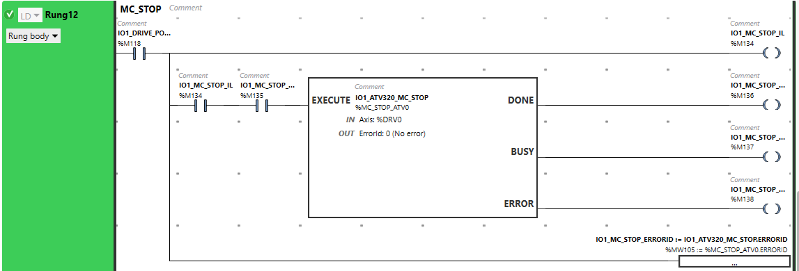
Rung12 MC_STOP
In Rung12, MC_STOPi(i=0-15) is used to send the stop commands to our ATV320 Drives via Memory bit.
Pou03_Outputs
Pou03_Outputs is the POUs to control the output Lamp of our Push Button.
Rung0 Power Status
%S6 is a system bit that generates a 1 second ON/OFF while the CPU is in running Mode.

Rung1 JOG Forward Status
If the operator is performing a Jog Forward operation, the Lamp will ON and flashing while the button is released, but the drive is still moving.

Rung2 JOG Backward Status
If the operator is performing a Jog Backward operation, the Lamp will ON and flashing while the button is released, but the drive is still moving.

Rung3 Move Vel Status
If the operator is performing a constant velocity moving, the Lamp will ON when the drive reaches the target and flashing while the button is released, but the drive is still moving or the drive is ramping to the target speed.

Result
Power On and Jog Operation:
MC_MOVEVEL_ATV ContUpdate=0
MC_MOVEVEL_ATV ContUpdate=1
Source Project
Please download the project from this link:
https://github.com/soup01Threes/Schneider/blob/main/State2_DrvObject_ModbusRTU.smbp