What is SINAMICS DriveSim Basic?
On May 31, 2021, Siemens will provide a model called SINAMICS DriveSim Basic that can be incorporated into Simulink and SIMIT.
Everyone, how do you make sure that the command and status are surely programming in the Drive before the program is put into the actual machine? With SINAMICS DriveSim Basic, you can check to some extent even before the actual machine is built. The SINAMICS DriveSim Basic is a PROFIdrive-Enabled FMU model (from my point of view, some parameters and Control words and Status words are used as input/output as they are). FMU = Functional Mockup Unit.
The FMU model can be imported into simulation applications such as SIMIT, Matlab Simulink and NX Motion.
Support Drive
Here are the Drives currently supported by DriveSimBasic:
- SINAMICS G110M (CU240M) – V4.7 SP13
- SINAMICS G115D – V4.7 SP13
- SINAMICS G120 (CU230P-2, CU240B-2, CU240E-2, CU250S-2) – V4.7 SP13
- SINAMICS G120C – V4.7 SP13
- SINAMICS G120X – V1.03.00
- SINAMICS G130/G150 – V5.2 SP3
- SINAMICS S110 – V4.4 SP3
- SINAMICS S120/S150 – V5.2 SP3
- SINAMICS S210 – V5.2 SP3
- SINAMICS V90 – V1.04.03
- a simplified representation of the motor
Support Telegram
At this stage, it will be Telegram1,2,3,4.
Version

Engineering
You can image SINAMICS DriveSim Basic is a toolbox to help you simulate the drive, and you can link this toolbox with other virtual tools like Simatic S7 PLCsim advanced or nx.
And I will implement the simulation with simulink in this tutorial.
use case
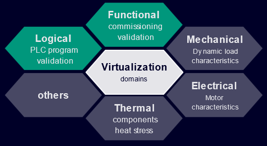
PLC Virtual commissioning
When designing a machine, you need to check whether your PLC program and Siemens Sinamics Drives are working properly. After the PLC program is downloaded to PLCSim Advance, PLCSim Advance embeds the SINAMICS DriveSim Basic FMU model into SIMIT or Simulink S-functions (PLCSim Advance version libraries provided by Siemens). Finally, you can simulate and check how the device works with NX or other software.
CU(Control Unit) Selection
SINAMICS DriveSim Basic can run independently with Simulink without PLCSim Advance. In that case, SINAMICS DriveSim Basic can load profiles from the User and directly load various characteristics (torque, speed, etc., there is a Siemens Drive selection software called SIZER). Then, the optimal CU, Converter and Motor will be selected from the Sizer. (This is also interesting, I will try it when I have time.)
Download
Please access this link to download the document,FMU and example.
https://support.industry.siemens.com/cs/document/109798225/sinamics-drivesim-basic?dti=0&lc=en-WW
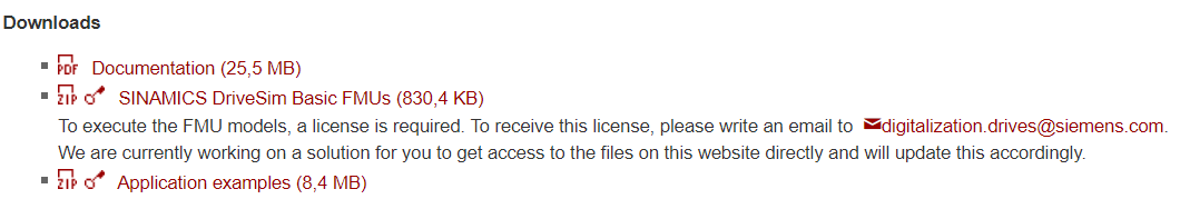
。It’s probably just released, so I wonder if the license and other relationships aren’t in place? License is required for FMU.
digitalization.drives@siemens.com
*If there is no license, an error will occur when simulating the FMU.
Licence
We need to request a license from
digitalization.drives@siemens.com.
Then you will receive a file that named
StartCode20.aut from the siemens support team.
Open your Auto License Manager and go to License Key>Offline Transfer。
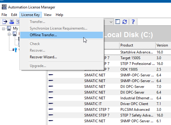
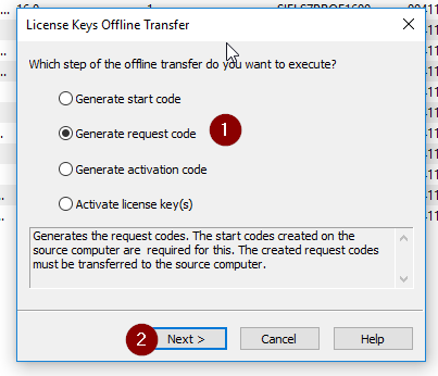
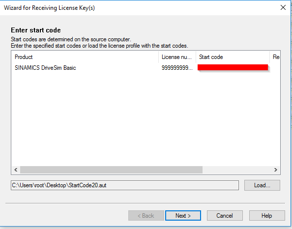
Choose Generate Request code,Next.
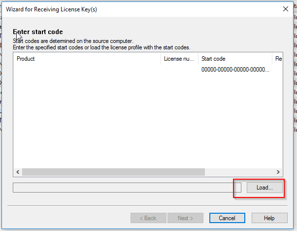
Then you can load the start code from the file.
Please load the file that received from Siemens support team.
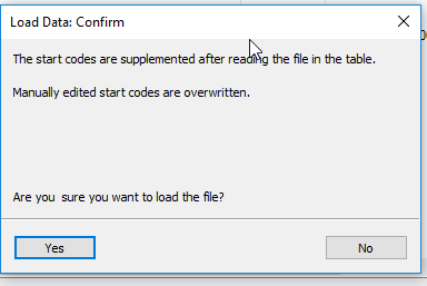
Are you sure you want to load the file?Yes.
Next.
Press the save button to save your Request code.
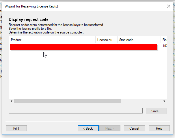
Then you need to send the request code to Siemens support team.
An activation file is received from support team again.
Open your automation license manager again,
Go to License Key>offline transfer.
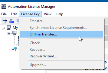
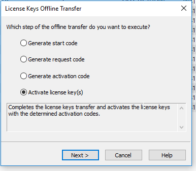
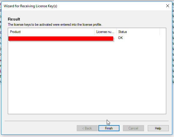
Choose activate license key(s) this time and press next.
Press the Load button.
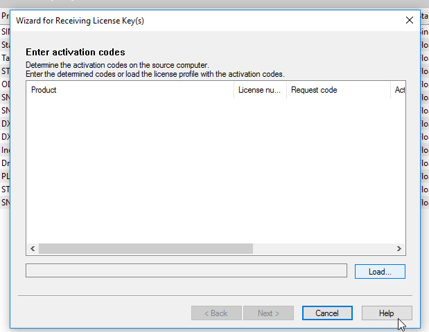
Choose the file that received from the Support Team and Next.
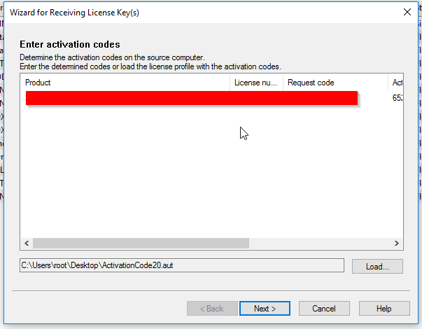
Done!
Block
I will use several blocks in this tutorial and let me introduce them one by one.
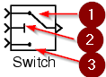
Simulink / Signal Routing / Switch
That are 3 lines in the switch blocks, the output data is come from line 1 or line 3(Data input ) ,depending the logical result of line2(control input)
https://jp.mathworks.com/help/simulink/slref/switch.html
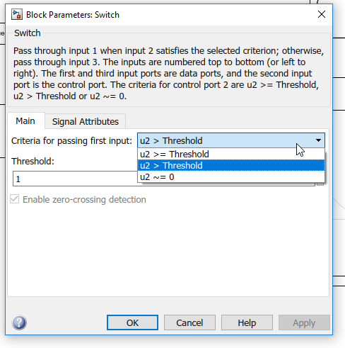
Sure that you can set the control condition of control input by double clicking the switch block.
Criteria for passing first input is the condition for using the value of link1.
> Or >=or not equal 0 can be configured.
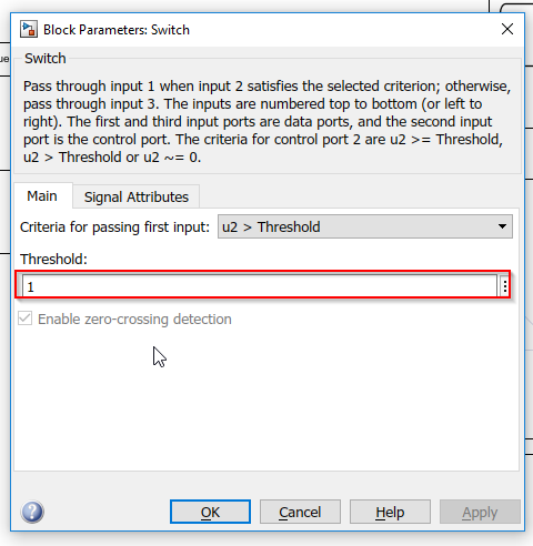
Threshold is the value for comparison.
Threshold can be constant or variable.
For example, if threshold is 1, it means the first input day will output while control input is >1.
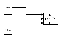
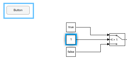
Here is another example where the first input is true and third input is false.
The output of this switch block is false because the condition of control input is >1 and the condition input is 1 now.
Simulink / Dashboard / Button
It is like a hmi button, the signal will be true if you press it, and the signal will be false if you release it.
https://jp.mathworks.com/help/simulink/slref/pushbutton.html

Insert a button into your model>one click > press the link button.
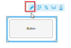
You can see the mouse icon has changed.
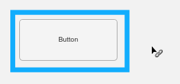
Select the block that you would like to connect with this button and finish the connection.
In the below example,I will connect the button to the switch block .
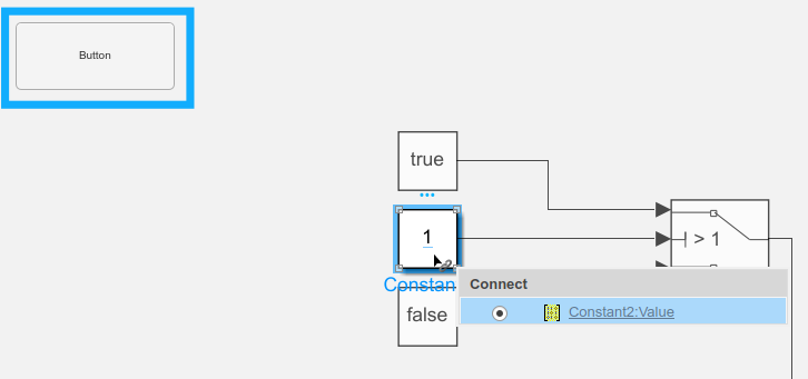
After these objects are linked,you can see the block will be highlighted while the button is selected.
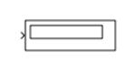
Simulink / Sinks/ Display
It is a component that displays the input data.
https://jp.mathworks.com/help/simulink/slref/display.html
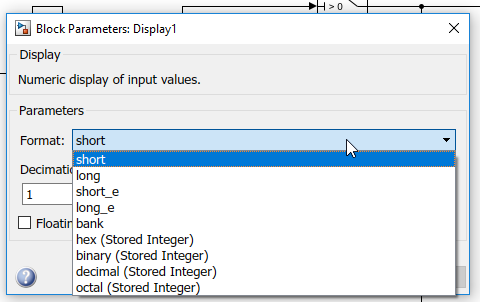
You can choose the display format from Block Parameters.
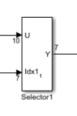
Simulink / Signal Routing / Selector
It is an object to let you choose which data that you would like to output.
In this tutorial I will use indexes to control the data flow.
U is the input of data,idx1 is the index control of your data set, finally y is the output.
https://jp.mathworks.com/help/simulink/slref/index-options-with-selector-block.html
you can configure the index option to match your application.
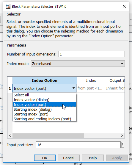
そして、Index選択するときは0から始まる(Zero-based)や1から始まる(One-based)の設定も可能です。
And also, a very great function that you can configure your index base- start from zero or start from one.
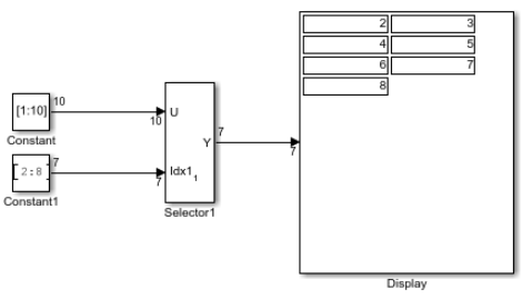
Here is a simple example. A vector that is configured as [1:10].now you would like to output the value from index 2 to 8.
These data will be output if you input a [2;8] into the indx1 parameter.
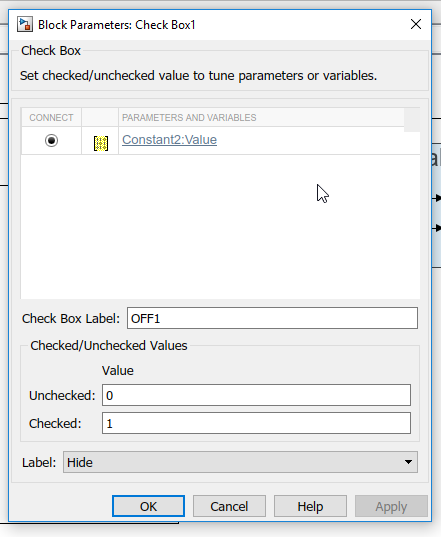
Simulink / Dashboard / Check Box
You can set the value of a parameter or variable during simulation by checking or unchecking this box.
The setting method of Connect is the same as the basic Button, so I won’t explain it in detail.
https://jp.mathworks.com/help/simulink/slref/checkbox.html

It is also OK to set the values separately when Label or Check is removed or inserted in Block Parameters.
For example, in the example below, Constant2, which is connected to Checkbox, is set to 0 when not checked and set to 1 when checked.
Simulink / Dashboard / Lamp
Here is an element that displays colors that indicate the value of the input signal. It’s not much different from what you’re using on a touch panel.
The method of Connect is similar to Button and Checkbox, so I won’t explain it in detail.
https://jp.mathworks.com/help/simulink/slref/lamp.html

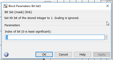
Simulink / Logic and Bit Operations / Set bit
Here is an element to set a specific bit of your stored integer to 1and Scaling is ignored.
You can specify which bit to set to 1 with the Bit index parameter. Bit 0 is the least bit.
https://jp.mathworks.com/help/simulink/slref/bitset.html
In this example, the block will set bit3 of input data to true.
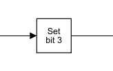
You can configure which bit would be set in the block parameters.
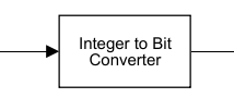
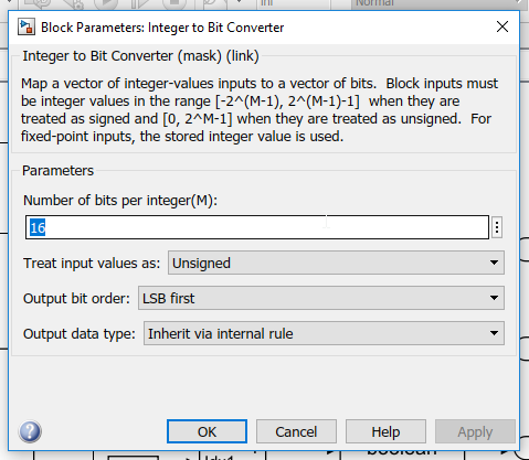
Communications Toolbox / Utility Blocks Integer to Bit Converter
A block to convert integer to bit data.
https://jp.mathworks.com/help/comm/ref/integertobitconverter.html
For Block Parameters, you can make detailed settings such as how many Bit Patterns are output and Bit order.
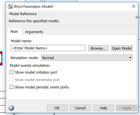
Simulink / Ports & Subsystems / Model
A block to call other models in your current model.
You can configure which model would be called in the block parameters.
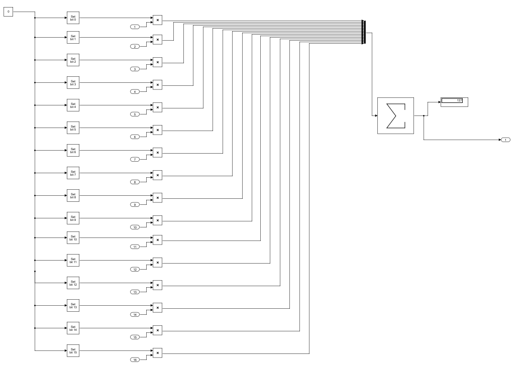
function_bit2word
Here is a block that I made to convert 16 bit data to a word.in plc it is used to group control word STW1.
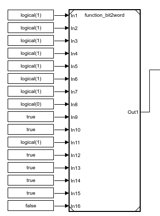
The logic inside this block is very easy and just used the set block to set a temp variable from bit 0-15 to true and multiple with the block input, finally sum these values as output.
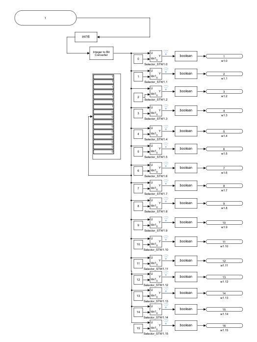
functiontest1
This is a block to separate one word to 16 bits .
It is used to encode the zsw.
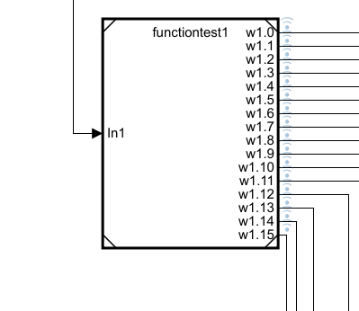
This is what the model looks like inside.
Convert Input to Integer and convert to Vector of Bit. Then use Selector Block to specify Index from 0 to 15 and output.
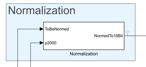
Normalization
this is an example block that comes from siemens.it will convert the control speed (xxxrpm) command to drive speed command.
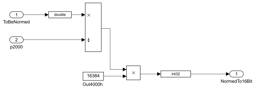
Here is the flow inside the block.p2000 is the max speed and 16384 (4000 hex) is the max value in max speed .
You can change the p2000 only if the max speed is changed.
Model
here is the model that I created.we have control command and display in the dashboard.
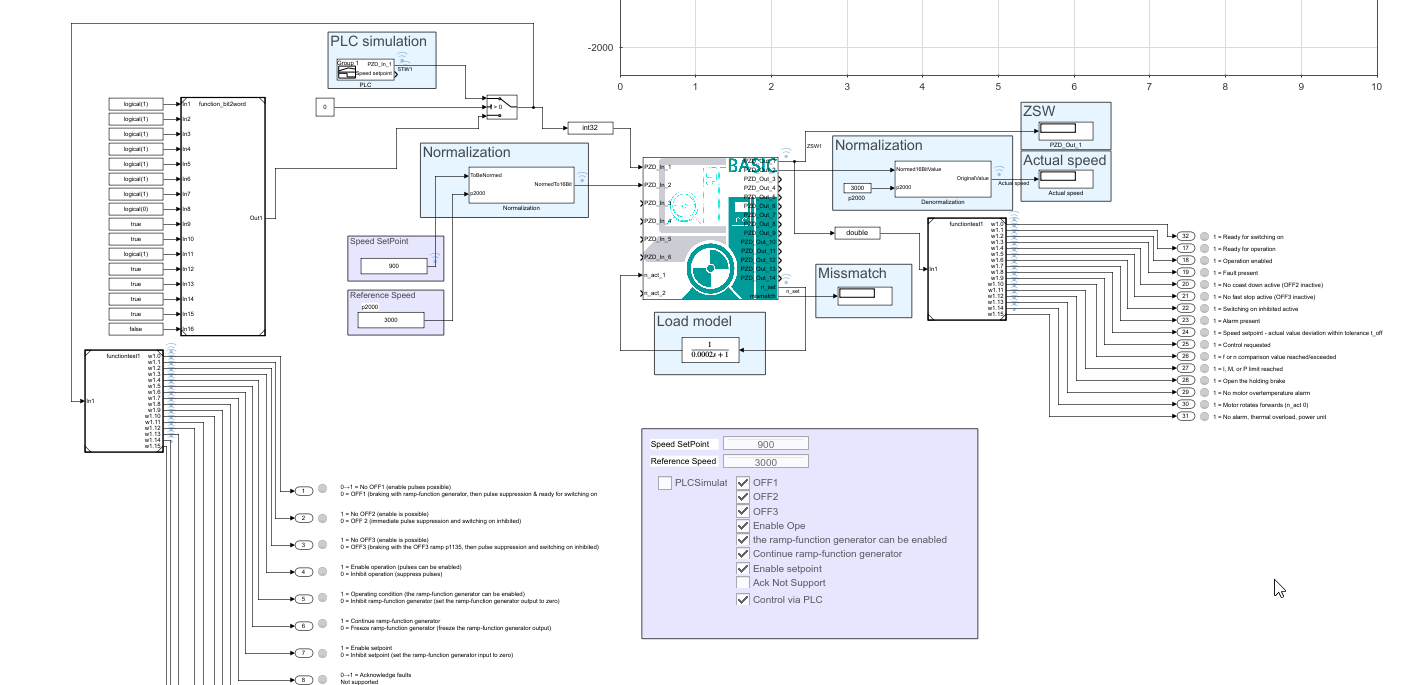

Result
