Hello and welcome to my blog again! In this series I will show you how to control the ATV320U15M2C with different CPUs,protocols,etc..
In the Part1,My task is :
- Operate the ATV320 seperately
- Configure the TM221ME16T Schneider CPU
- Control the ATV320 from TM221ME16T with Digital and Analog Signals
Implementation-1
In the implementation1, I will show you how to operate the drive with the Digital Input and Analog Input of the terminal that was built in the ATV320.
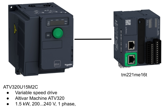
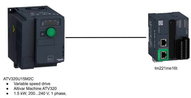
ATV320U15M2C
Altivar 320 is a speed drive that can feed a single-phase synchronous and asynchronous motors.The rated power of this drive is up to 1.5kW/2hp from 200V to 240V AC.Also – this drive is fully integrated inside the Schneider Electrical’s EcoStruxure Machine though DTM.
We can configure/control/diagnose this drive directly from Somachine and Somove Software.

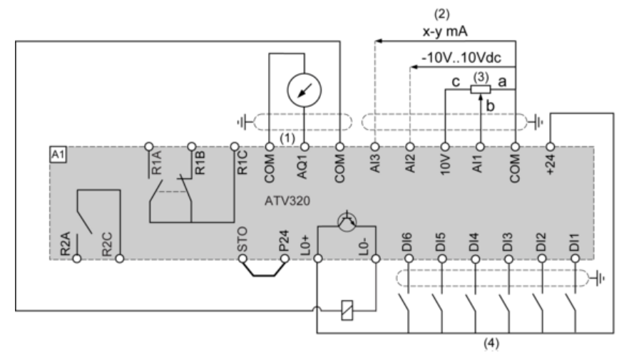
Connection Diagrams
Here is the Connection Diagrams example from Schneider ATV320 Manual – But in my case I will only have the 110v to 220v transformer and no motor is connected.

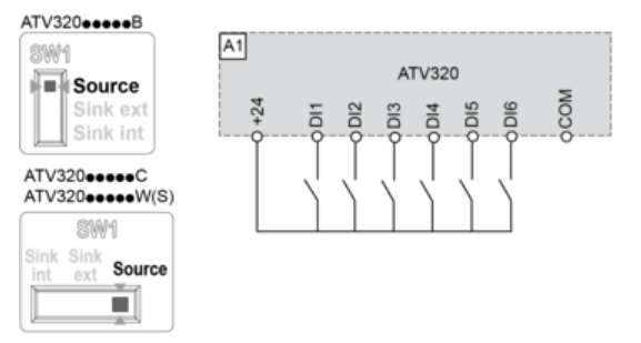
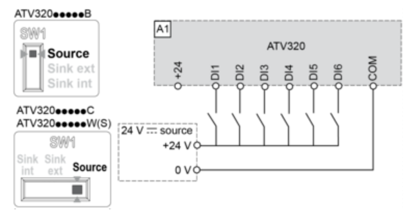
Control Connection Diagram in Source Mode
Here is the Connection Diagram example that connects the Signal with Source Mode.
DI Wiring
ATV320U15M2C is used in my tutorial here is the Digital Input wiring with Source mode.
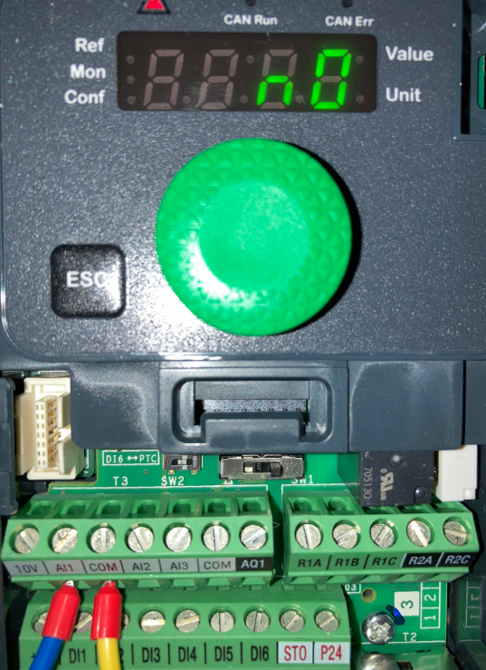
Commissioning
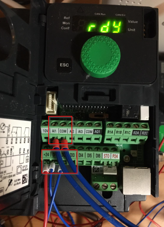
Before we start to connect with Schneider PLC, A commissioning step is very important that make sure our inverter is running normally.There are a terminal board on the ATV320,
And Reference from the ATV320 Manual,DI1=FW,DI2=BW,AI1=Speed Setpoint
DI1/DI2

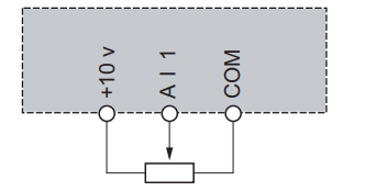
AI1
For the Voltage analog input, the available range is from 0- +10Vdc and the Sampling time is 2ms.
Important Parameters
Go to “ConF→FuLL→SiN-(Simple Start) Menu,and there are some parameters that you need to configure.
bFr(Standard motor frequence)
The standard motor Frequency in Hz.Factory Setting=50.0Hz
nPr(Rated motor Power)
The rated motor power on the motor nameplate in KW.
un5(Rated motor Voltage)
The rated motor voltage on the motor nameplate in V.
nCr(Rated motor Current)
The rated motor Current on the motor nameplate in A.
Fr5(Rated motor freq)
The rated motor Frequency on the motor nameplate in Hz.Factory Setting=50.0Hz
nSP(Rated motor Speed)
The rated motor speed on the motor nameplate in rpm.
iTH(Motor thermal monitoring current)
The motor thermal monitoring current in A.
ACC(Acceleration)
The Acceleration time in second.
dEC(Deceleration)
The Deceleration time in second.
LSP(Low Speed)
The Motor Frequency at minimum reference in Hz.Factory setting=0.0.
HSP(High Speed)
The Motor Frequency at maximum reference in Hz.Factory setting=50.0.
Terminal
Here are the terminals that used in commissioning.
Remove the Power Cover
Here is the video to show you how to remove/install the power cover of ATV320.
Factory Reset
Here is the process to perform a Factory Reset.
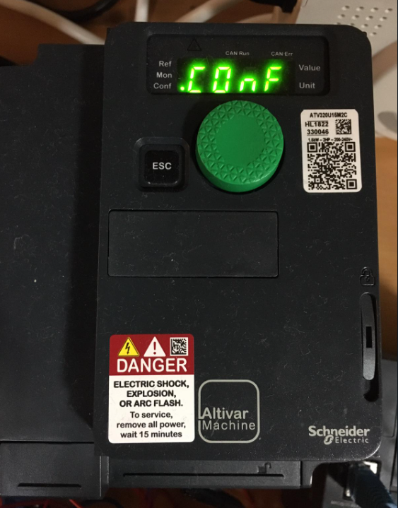
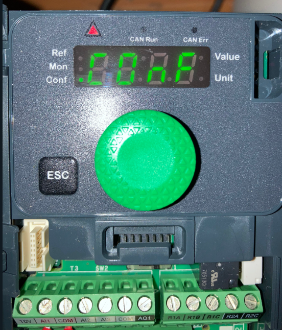
Go to COnF menu.
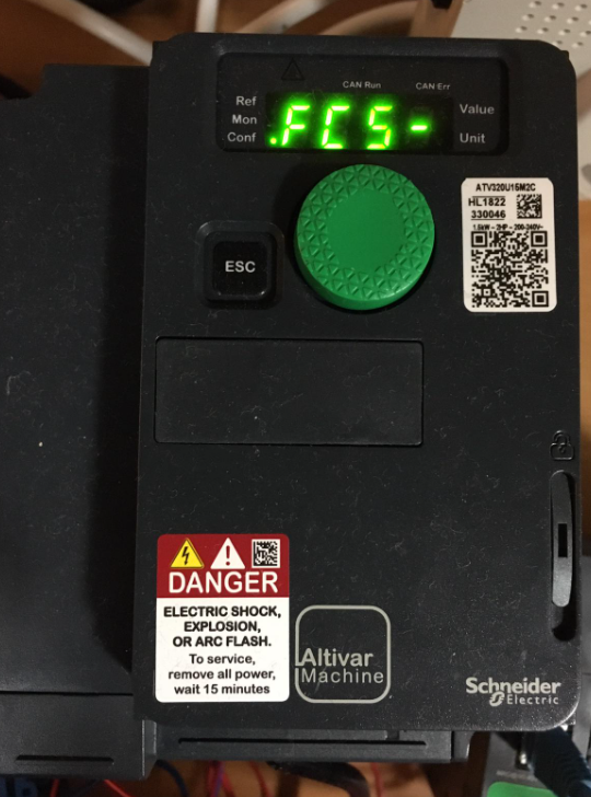
Jump to FC5-.
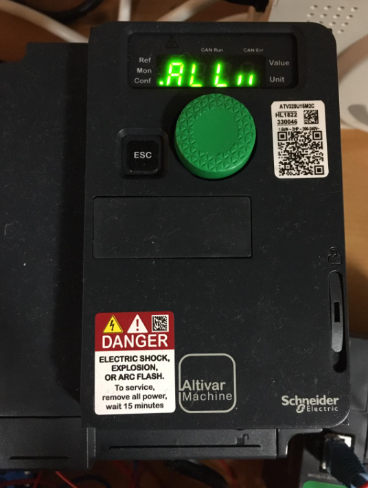
Set to All.
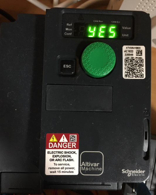
Open the GF5 Menu.

Set it to “YES” to start a factory Reset.
Result
You can check out the result from this link.
Error?
An “OPF2” error occurred while I was operating the Drive.
“OPF2” is an error that is named 3 motor phase loss – it will happen while the motor is not connected or power is too low.As I mentioned before, I will not connect the motor with this inverter – So it should be the reason for this fault.

Operate the Panel and Go to “ConF” Menu.
Go to the “FULL” Menu.

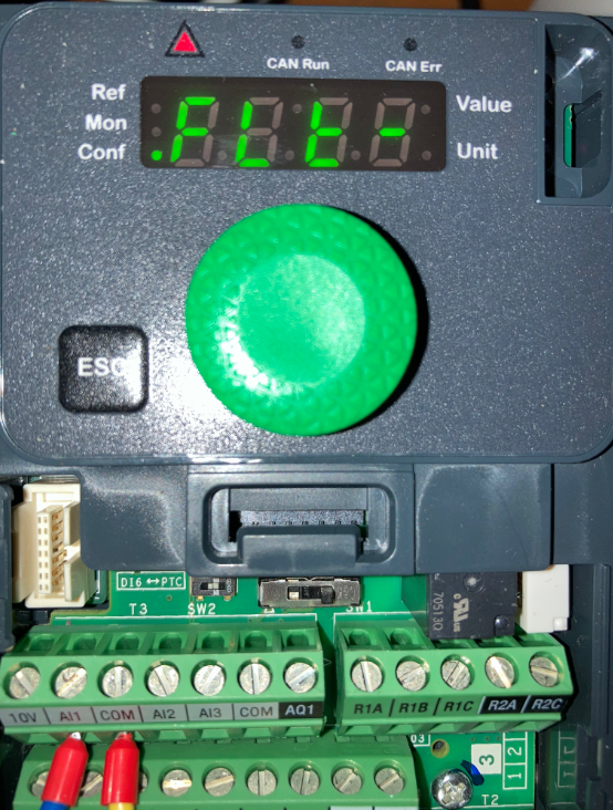
Go to the “FLE” Manual.
Open the “OPL” Menu.
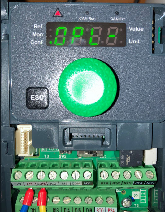
change the parameters to “nO” to Disable the “OPF2” Fault and turn on the power again.
Implementation-2
After we confirmed the ATV-320 inverter can operate without problem, the next step is to prepare the PLC Side. In my first tutorial , Schneider tm221me16t and analog module TM3AM6G is used.
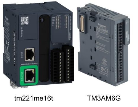
TM3AM6G Mixed I/O Module 4 Inputs/2 Outputs
This module is a part of Modicon TM3 range – an offer of expansion I/O Module for the Modicon M221/M241/M251 and M262 CPU. 4 Inputs and 2 Outputs with 11 Bit+sign and 12 bit input resolution is provided from this module,with a External 24 V DC Supply.

Main Characteristic

Status LED
There is a PWR LED on the surface of the TM3 module to indicate the power status of the module itself.
| LED | Color | Status | Description |
| PWR | Green | On | Power is applied |
| Green | Off | Power is removed |

Wiring
Here is the wiring of this module.

Installation
Here is the video to show you how to install/uninstall the module to your Schneider CPU.
https://youtube.com/shorts/cFUjQG4Ynws
M221 Side
Reference Link
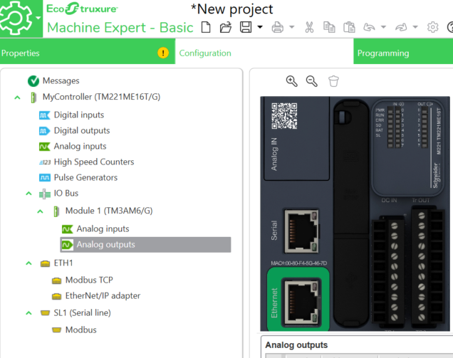
Hardware Configuration
Open the EcoStruxure Machine Expert Basic and create a new project, open the Configuration Tab.
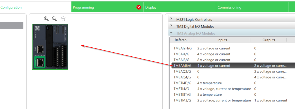
Add Modules
Open the TM3 Analog I/O Modules Menu, and Select TM3AM6/G.
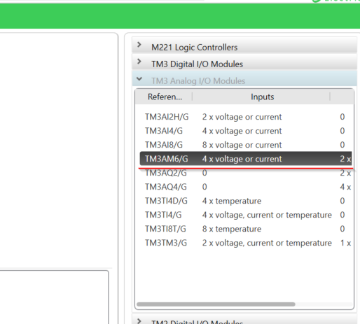
Drop this module in your Hardware Configuration.
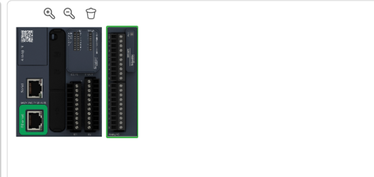
Done!TM3AM6G is inserted into your Hardware Configuration.
Modules Configuration
Now we can Configure our TM3AM6G Module.
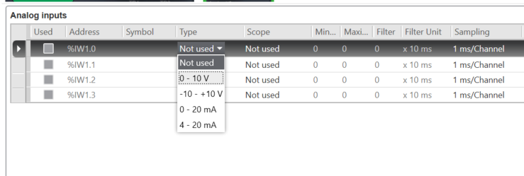
Analog Inputs
Click the IO Bus>Analog Inputs, the Analog Inputs Configuration View is shown.

Choose the measurement range, 0-10 V is used in my tutorial.
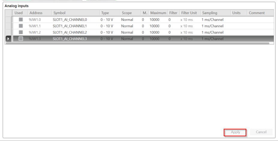
Do not forget to enter the Symbol Name>Apply to save.
Ananlog Outputs
Do the same operation for the Analog outputs.

Enter the Symbol name and configure your measurement type>Apply to save.

Program
Now we can start to make the program.
Add User-defined functions
A User-defined function is created to process the Analog output Command.

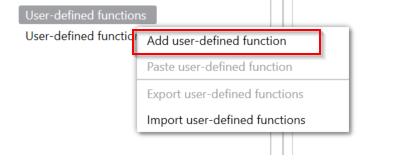
Right Click the User-defined functions>Add user-defined function.
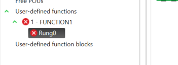
A new Function is added.
Rename it
Right Click your new function>Rename user-defined function to change the function name.

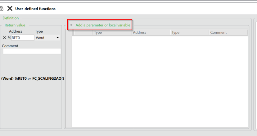
Configure the Return Type
Now we can configure the return value. you can imagine this value is the result after the execution of your function.
In this case, %RET0 is the name of your Return value, and you can choose the data type of that return value, word(16 bit integer),Double(32 bit integer),Float can be configured in here.

Configure the Parameters
Then we can press the “Add a parameter or local variable” to Add the input parameters or local variables from here.
a variable is added in your function.
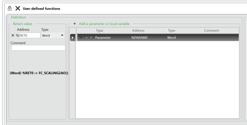
you can choose “Parameter” or “Variable” as the variable type.
Parameter=Input Parameter and Variable=Local Variables.
In my case, parameter type with Word format is used.

Program
Here is the Program inside the function. we will write a 0 for the return value first, and if the Parameter is inside our acceptable range, the parameter value can overwrite the return value.It is a sample program to make sure the setpoint value to the Analog Output Module is correct.
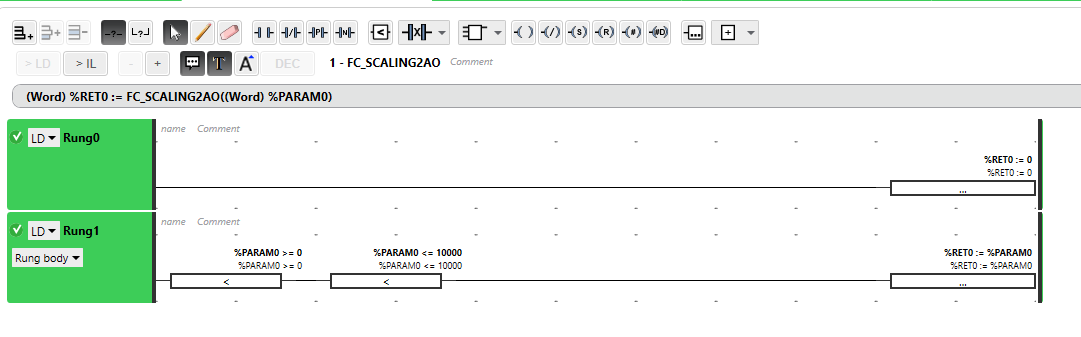
MAIN PROGRAM
Now we can create the main program.

Drop an operation block into the Rung.

An operation block is inserted.
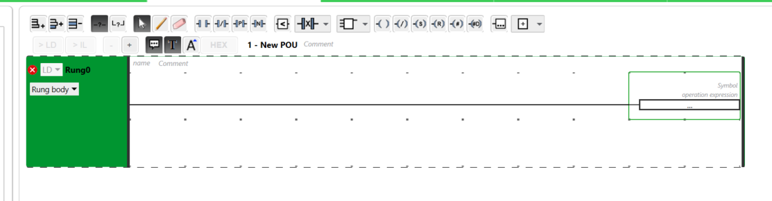
Finally we just need to type in the function name and fill in the parameter and return value.
Here is the Program. Rung0 and Rung1 are the interlock to protect FW Command and BW Command will not output at the same time.
Rung2 will reset the command while no FW and BW are both false.
Finally we can use the user-defined function to check if the value is acceptable or not.

Implementation-3
In the Implementation3, I will group-up the ATV320 and TM221ME16T CPU – output the Forward/Backward command and the Speed Setpoint from the CPU to control the ATV320 Drives.
AT320 Side
Di Wiring
Because we will use the Signals from Schneider CPU – the Digital Input is changed to External Power source.
Result
You can check out the result from this link:
Source Project
Please download the project from this link:
https://github.com/soup01Threes/Schneider/blob/main/State1_TestingwithATV320.smbp