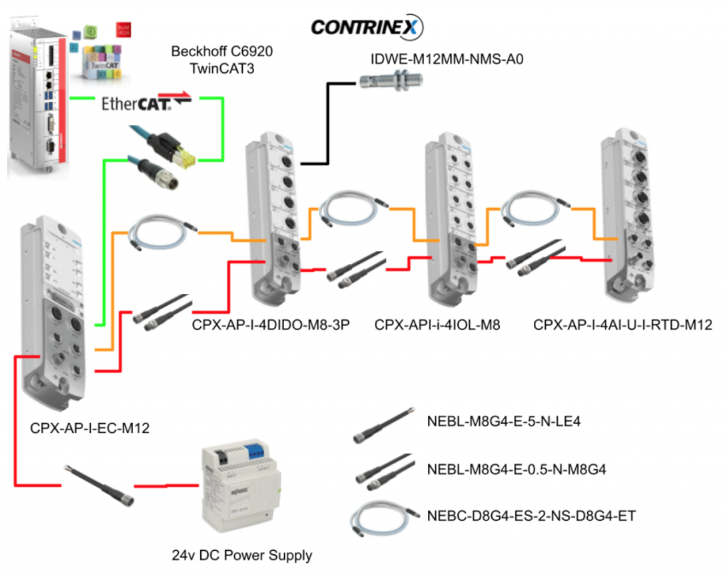
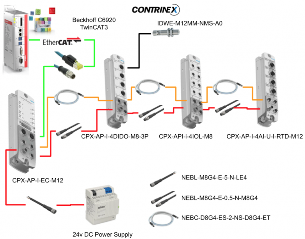
In this article, we will be using Festo’s CPX-API-EC-M12 to set up an EtherCAT network and acquire data and control from an IO-Link master module, DIDO module, and an analog input module. The EtherCAT master will be the Beckhoff C6920 IPC with TwinCAT3, and the IO-Link sensor will be from Contrinex.
Let’s Start!
Thanks!
This article was made possible thanks to the equipment rented by Beckhoff Automation K.K., Festo Corporation, and Contrinex Japan. I am truly grateful for their support.
Beckhoff Automation Japan
IPC6920-005 was lent by Beckhoff Automation Japan. Beckhoff Automation is a German company that was founded in 1980, and is at the forefront of introducing open automation systems based on PC-based control technology.
Beckhoff Automation Japan, Beckhoff Automation Corporation established its headquarters in Yokohama in 2011, and opened a Nagoya office in 2017.

Here is the website of Beckhoff Automation Japan:
https://www.beckhoff.com/ja-jp/
Festo Japan
CPX-AP-I Series was lent to us by Festo Corporation. Festo is a global leader in automation technology and offers a range of reliable products for both factory and process automation, including pneumatic servo actuators, remote I/O, and software. In addition, they also focus on providing technical education and offer various training programs for companies.

Here is the website of Festo Japan:
Contrinex Japan
The IO-Link sensor was lent to us by Contrinex Japan. Contrinex is a Swiss company that specializes in manufacturing smart sensors for complex automation and smart factory applications. With over 50 years of experience, they constantly provide inductive and photoelectric sensors as well as safety and RFID systems technology.

Here is the website of Contrinex Japan:
https://www.contrinex.com/en-jp
CPX-AP-I-Series?
The CPX-AP-I series we are introducing today is Festo’s new IP65/67 IO system, which can be integrated with input/output modules and existing valve terminals as a host system. The CPX-AP-I is divided into an Interface Module and a Function Module. The Interface Module is a module that connects to the so-called upper-level systems (PLCs and PCs, for example). Therefore, from the perspective of the PLC or PC, the CPX-AP-I is a slave. On the other hand, the CPX-AP-I is also a master, and by using Festo’s APC Com, it collects data from digital inputs, IO LINK Master modules, and sends commands. Therefore, from the perspective of the Function Module, the CPX-AP-I is a master.

Your Module Selections
- IO-Link Master
- Digital IO Module
- Analog Module
- Interface to the valve terminal
- Bus Interface
Bus Interface

IO-Link Master
The IO-LINK Master can construct areas of 2, 4, 8, 16, and 32 bytes, and the one we will be using in future articles is the CPX-AP-I-4IOL-M12.

Digital IO Modules
For the basic digital input/output module, we will be using the CPX-AP-I-4DI4DO (PNP Type) in future articles.

Analog Input Modules
For the analog input module that can measure current, voltage, temperature, and other signals, we will be using the CPX-AP-I-4AI-U-I-RTD-M12 in future articles.

Topology
At present, the wiring configuration supports 1 or 2 lines. Support for start and tree topology is planned for the future. The maximum cable length between each module is 50 meters, and up to 80 modules can be connected (with a choice of M12/M8 wiring).
Address Space
There are three types of CPX-API-I available for Ethernet/IP, Profinet, and EtherCAT.
CPX-AP-I-PN-M12
The PN version of CPX-API-I supports a maximum input size of 1024 bytes and a maximum output size of 1024 bytes for Profinet.
CPX-AP-I-EC-M12
The EC version of CPX-API-I supports a maximum input size of 2048 bytes and a maximum output size of 2048 bytes for EtherCAT.
CPX-AP-I-EP-M12
EP stands for Ethernet/IP, with a maximum input size of 1024 bytes and a maximum output size of 1024 bytes.
CPX-AP-I-EC-M12
This is the EtherCAT interface module that we will be using in this article.
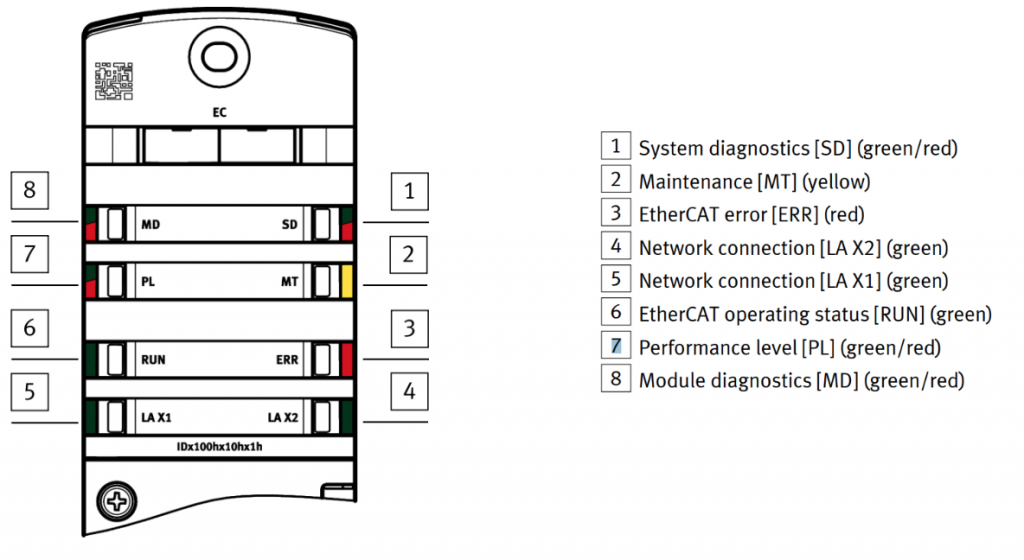
LED
Here are the meanings of each LED on the module.
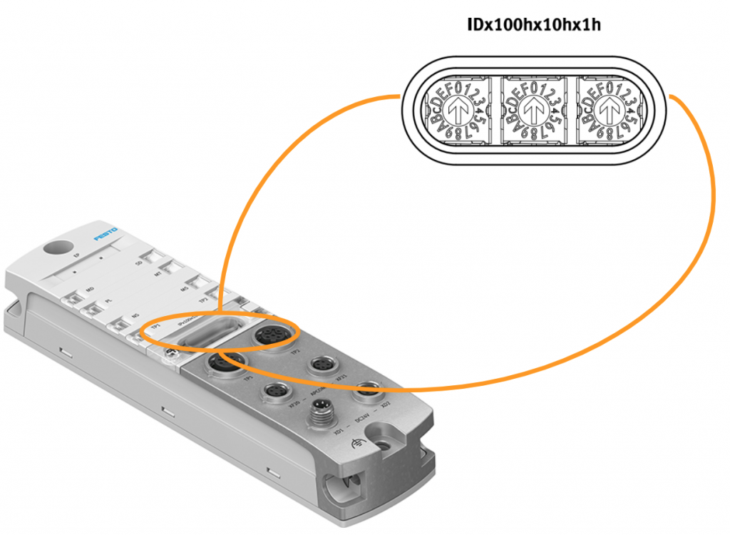
Rotary Switch
The module has three rotary switches that can be used to set the Explicit Device ID (HEX format) for EtherCAT communication. The factory setting is 0, which means the Explicit Device ID is not set. The available range for Explicit Device ID is 1-4095.
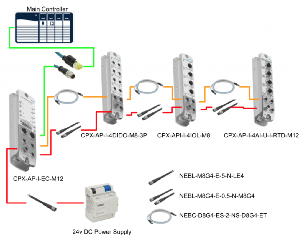
Configuration Example
This is an example of a configuration when using the CPX-AP-I series. The CPX-AP-I-EC-M12 (EtherCAT) will be used in this case, but it can be adapted to the Industrial Protocol supported by the Main Controller. The Interface module of the CPX-AP-I is connected to the RJ45 connector of the Main Controller with an IP67 rating, and the power supply uses a NEBL-M8G4-E-5-N-LE4 cable with 24V. Finally, the Interface module and the IO module are connected using a linear wiring with a NEBL-M8G4-E-0.5-N-M8G4 (24V power supply) and a NEBC-D8G4-ES-2-NS-D8G4-ET (AP-COM).
Download ESI File
Please download the ESI file from the following link for the EtherCAT CPX-AP-I-EC-M12 that we will be using in this article.

Zip is downloaded.

Implement-TwinCAT
This time, we will verify the CPX-AP-I-EC-M12 using Beckhoff’s IPC 6920 and TwinCAT as the main controller.
Notes
CPX-AP-I-EC-M12
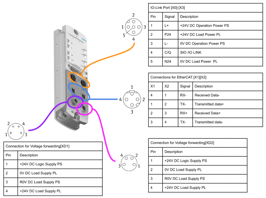
Wiring
Here is the wiring diagram for each port of CPX-AP-I-EC-M12:
CPX-AP-I-4IOL-M12
Wiring
Here is the wiring diagram for each port of CPX-AP-I-4IOL-M12:
Mappings
This is the Byte PQI that allows you to check the status of each port:

CPX-AP-I-4AI-U-I-RTD-M12
Wiring
Here is the wiring diagram for each port of the CPX-AP-I-4AI-U-I-RTD-M12 module.
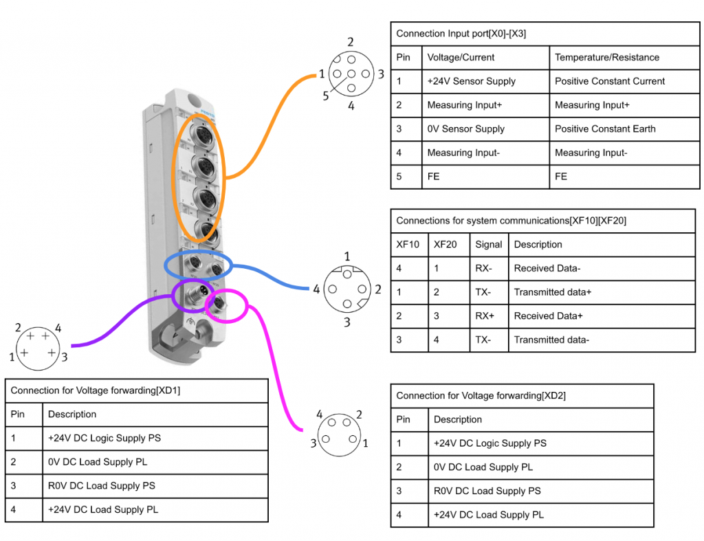
For the CPX-AP-I-4AI-U-I-RTD-M12 module that we are using today, the wiring for each port is as follows:For voltage input (0-10V), connect the positive wire to terminal 2 and the negative wire to terminals 3 and 4 (short-circuited). Terminal 1 is for the sensor’s power supply (24V).

Range
Here are the digital values when the module is set to measure within the range of 0-10V.

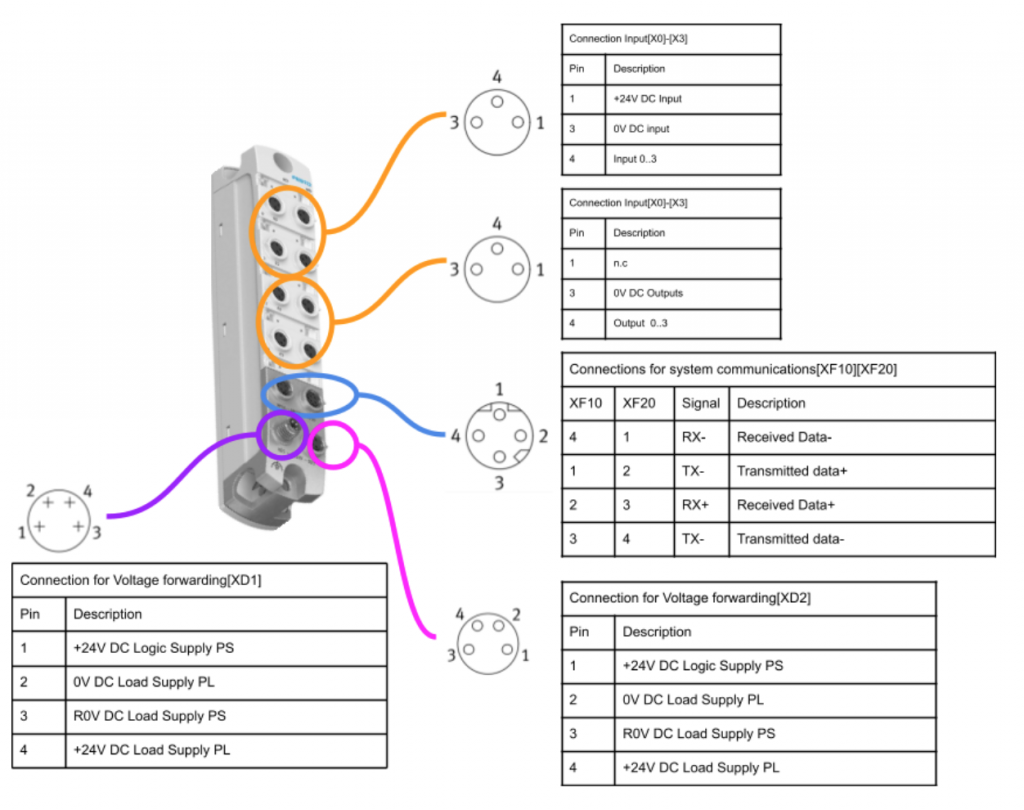
CPX-AP-I-4DI4DO
Wiring
This is the wiring diagram for each port of CPX-AP-I-4DI4DO.
IOLINK Sensor
We will be using the Contrinex Smart IO-Link Sensor for this project. In this first episode, we will cover basic information such as wiring and data mapping. In the next episode, we will explain the settings in more detail. This IO-Link Sensor has 4 bytes of input and 1 byte of output.
Wiring
Bn=Brown, Bk=Black, Wh=White, Bu=Blue.

Pin
Here is the pinout configuration.

Input Data
For the 4-byte input data mapping, the 0th byte represents the sensor status, the 1st byte represents the scaling value, and the 2nd and 3rd byte represent the measured value.
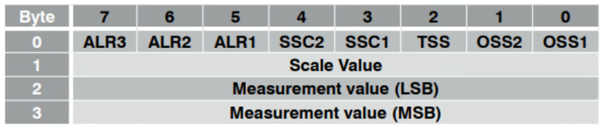
Byte0 Mapping
Here are the assignments for each bit in 0th byte.

Output Data
The Output Data consists of 1 byte.

DIS Mapping
0=Sensor disabled・1=Sensor enabled.

Install the ESI File
Move the ESI File that you downloaded from Festo HP to TwinCAT/3.1/Config/io/EtherCAT Folder.

Add EtherCAT Master
Go to I/O>Devices>Add New Item to insert an EtherCAT Master.

Go to EtherCAT and choose EtherCAT Master>OK.

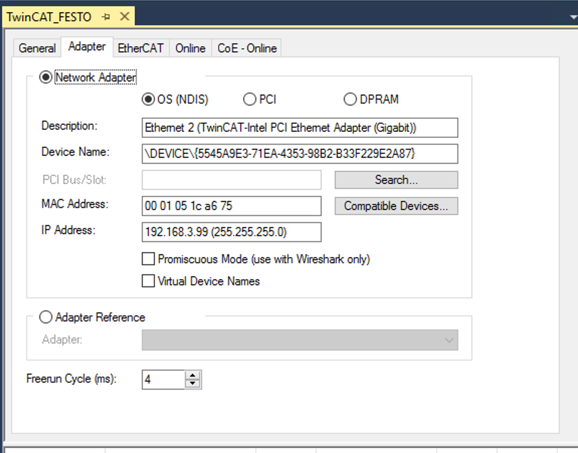
Choose the Network interface that you need to use in your IPC.

And please double check on the Adapter Tab.
Try to Scan it
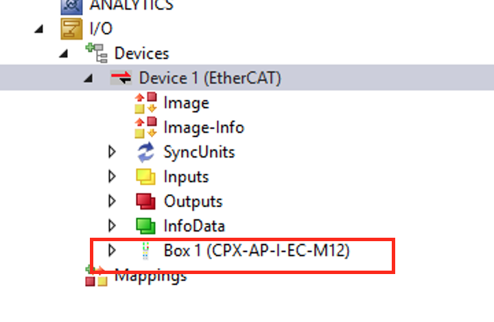
Firstly, we will use the Scan function in TwinCAT to scan the Festo CPX-AP-I-EC-M12 module.

Great!CPX-AP-I-EC-M12 is found.
But not all modules can be found by using this scan method. It is better to add the module inside your configuration one by one.
Configure your CPX-AP-I-EC
Add CPX-AP-I-EC
Right Click the EtherCAT Master>Add New Item.

Choose Festo>AP>CPX-AP-I-EC-M12 and OK.

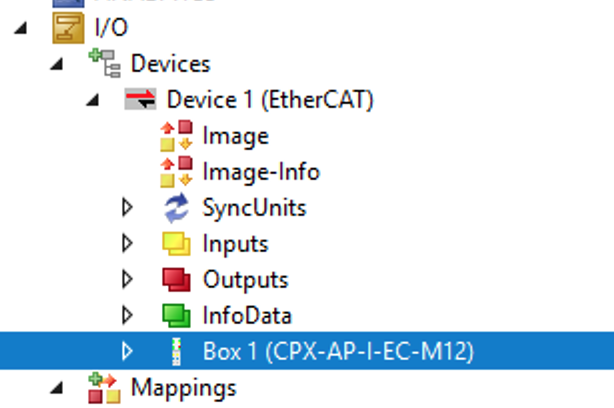
Festo CPX-AP-I-EC-M12 is inserted.
Configure the Slot
Now you can insert the module into each slot.

CPX-AP-I-EC-M12
Open the Slots tab and insert CPX-AP-I-EC-M12 into slot1 by clicking the “>” Button.

CPX-AP-I-4IOL-M12 Varian 32
Insert the IO-Link Master into slot2 and In/Out IO LINK data of 32 bytes is used if you choose “Variant 32” into the slot.

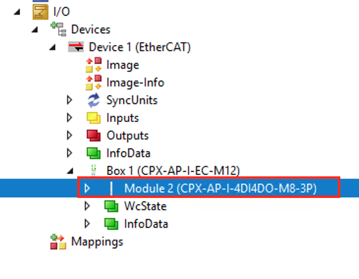
CPX-AP-I-4DI4DO-M8-3P
Choose CPX-AP-I-4DIDO-M8-3P and click “<” to insert it into slot3.

CPX-AP-I-4AI-U-I-RTD-M12
Finally we will choose CPX-AP-I-4AI-U-I-RTD-M12 and insert into slot4.

Finally
Here is the final configuration.

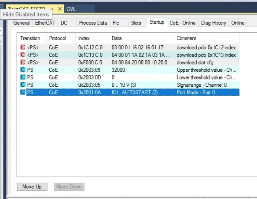
Configure Startup
Open the Startup Tab and we can configure the parameters of each module.
(you can imagine that the EtherCAT master will write all parameters from this table to each Ethercat Slave.)

Click “New” to create a new startup parameter.

Edit CANopen Startup Entry screen is displayed.

Let’s try to configure the Upper Scaling of CPX-AP-I-4AI-U-I-RTD-M12’s channel0.
we can choose 2003:09 and click “Edit Entry”.
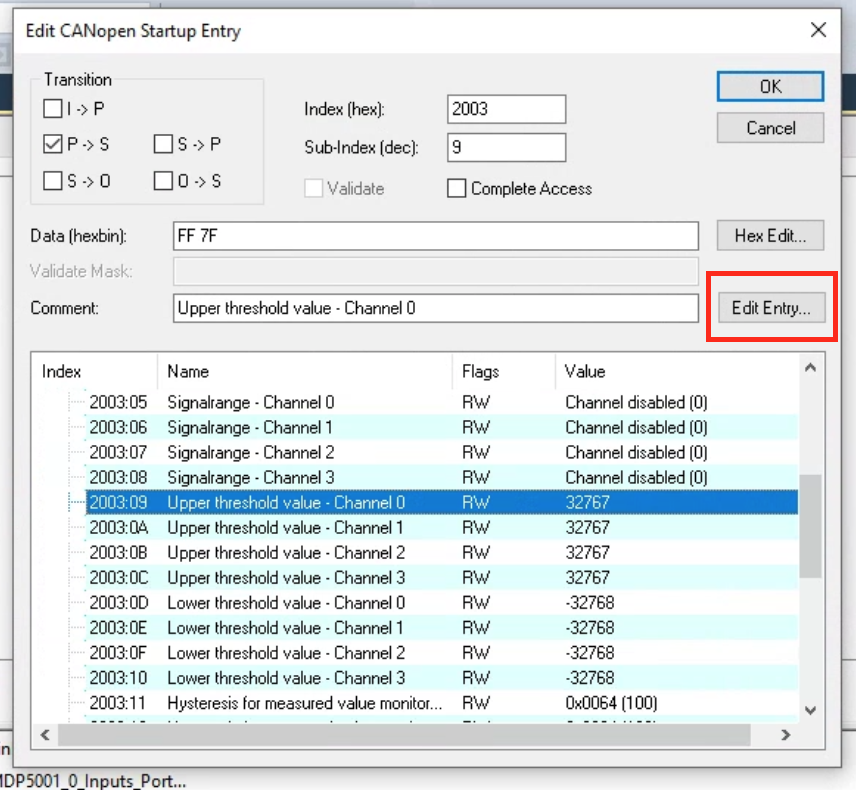
Enter 32000 and OK.

In this tutorial, the parameters that we need to configure are:
- 0x2003:09 CPX-AP-I-4AI-U-I-RTD-M12 Channel0’s Max Scaling
- 0x2003:0D CPX-AP-I-4AI-U-I-RTD-M12 Channel0’s Min Scaling
- 0x2003:05 CPX-AP-I-4AI-U-I-RTD-M12 Channel0’s Scaling Type
- 0x2001:0A Configure CPX-AP-I-4IOL-M12 Port0 as IO-LINK Port
Add PLC
Go to PLC>Add New Item to add a new PLC.

Choose Standard PLC Project>Add to create a new project.

Add GVL
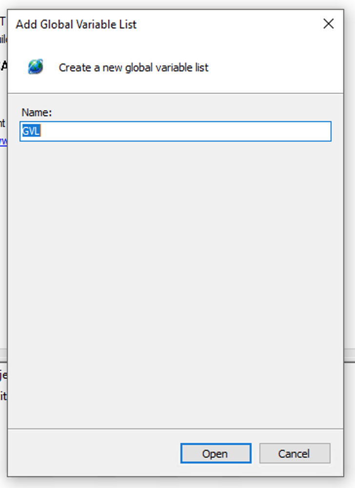
Go to GVLs>Add>Global Variable List to create a new GVL.

Enter your GVL name.
Creare Data Type
In previous tutorials, TwinCAT was mapping variables one by one. However, it is possible to create a structure directly from IO Configuration and link it directly to variables in the User Program. In this tutorial, I will introduce this method. Click on the Festo CPX-AP-I-EC-M12 that was added earlier.

Open the PLC tab and check the “Create PLC Data Type” checkbox.
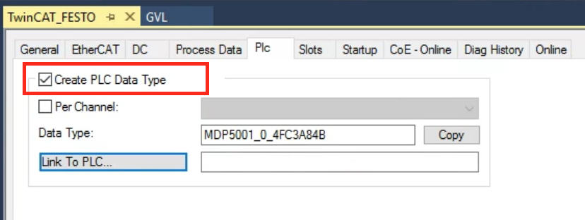
The variable that contains the information for each module of the Festo CPX-AP-I-EC-M12 that was added earlier is “MDP5001_0_4FC3A84B”. Copy the name of the structure using the Copy button.

Define in GVL
Now we can define the Variables that inside GVL.

Build
Go to Build>Build Solution to compile your project.

Link To PLC
Press the “Link to PLC” button in the Plc Tab.
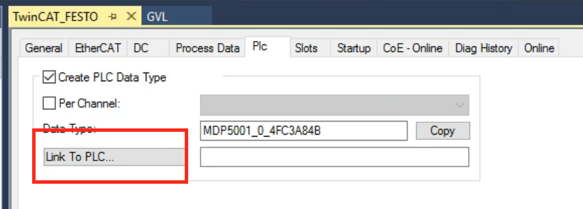
Link the variables in the GVL.

Done!

DUT
DUT_SMART_IDWx_MxxMM_NMS_A0
This is the data mapping of はContrinex Smart Sensor in Byte0.
| TYPE DUT_SMART_IDWx_MxxMM_NMS_A0 : STRUCT OSS1 :BIT; //Output switching signal OSS2 :BIT; //Output switching signal TSS :BIT; //Timer Selected signal SSC1 :BIT; //Switching signal SSC2 :BIT; //Switching signal ALR1 :BIT; //Alarm ALR2 :BIT; //Alarm ALR3 :BIT; //Alarm END_STRUCT END_TYPE |
Program
To work with the data from the Contrinex sensor connected to Port 0 of the Festo CPX-I-4IOL-M12 module, or the output data from Port 4 of the CPX-I-4DI4DO-M8 module, or the analog input data from Port 0 of the CPX-AP-I-4AI-U-I-RTD-M12 module, you will need to map the respective variables in IO Configuration and link them to variables in your User Program.
| PROGRAM MAIN VAR TON :TON; TON2 :TON; ScalingValue :REAL; Process_Data_0 :DUT_SMART_IDWx_MxxMM_NMS_A0; Process_Data_1 :USINT; Process_Data_2 :INT; PQ,DevErr,DevCom :BOOL; END_VAR //Festo IOLINK Module Port1 Status PQ:=GVL.Festo_Module1.MDP5001_0_Input.MDP5001_0_Inputs_Port_4_IECCONF_IECCONF_PQI.7; DevErr:=GVL.Festo_Module1.MDP5001_0_Input.MDP5001_0_Inputs_Port_4_IECCONF_IECCONF_PQI.6; DevCom:=GVL.Festo_Module1.MDP5001_0_Input.MDP5001_0_Inputs_Port_4_IECCONF_IECCONF_PQI.5; //Reflesh Timer TON(IN:=NOT TON2.Q,PT:=T#1S); TON2(IN:=TON.Q,PT:=T#1S); //Scaling Value ScalingValue:=(INT_TO_REAL(GVL.Festo_Module1.MDP5001_0_Input.MDP5001_0_Inputs_Channel_0)/32000.0)*10.0; //DO Output GVL.Festo_Module1.MDP5001_0_Output.MDP5001_0_Outputs_Output_0:=TON.Q; //IO LInk Sensor MEMMOVE( destAddr:=ADR(Process_Data_0) ,srcAddr:=ADR(GVL.Festo_Module1.MDP5001_0_Input.MDP5001_0_Inputs_Port_0[0]) ,n:=SIZEOF(Process_Data_0) ); Process_Data_1:=GVL.Festo_Module1.MDP5001_0_Input.MDP5001_0_Inputs_Port_0[ Process_Data_2:=GVL.Festo_Module1.MDP5001_0_Input.MDP5001_0_Inputs_Port_0[3] +SHL(BYTE_TO_INT( GVL.Festo_Module1.MDP5001_0_Input.MDP5001_0_Inputs_Port_0[2]),8) |
Result
Done!System is started up without errors.

This is the normal state of CPX-AP-I-4IOL-M12:
https://youtube.com/shorts/pa8ETzEVasg
This is the error state of CPX-AP-I-4IOL-M12:
https://youtube.com/shorts/_h1rbWSqmuo
This is the recovery state of CPX-AP-I-4IOL-M12 after an error: https://youtube.com/shorts/BetMhY04vyw
This is the state of CPX-AP-I-4IOL-M12, TwinCAT3, and Contrinex IOLINK Sensor in operation:
This is the state of CPX-AP-I-4AI-UI-RTD-M12 reading analog signals:
This is the On/Off output cycle of CPX-AP-I-4DI4DO-M8-3P: