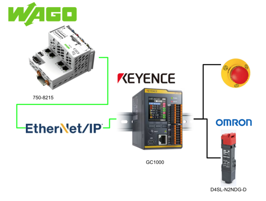
The GC1000 can support EtherNet/IP™, PROFINET, UDP, Modbus/TCP, or MC protocol communication. This article is about EtherNet/IP communication between WAGO PFC200 Controller and GC1000.
Let’s get started!
Reference Link
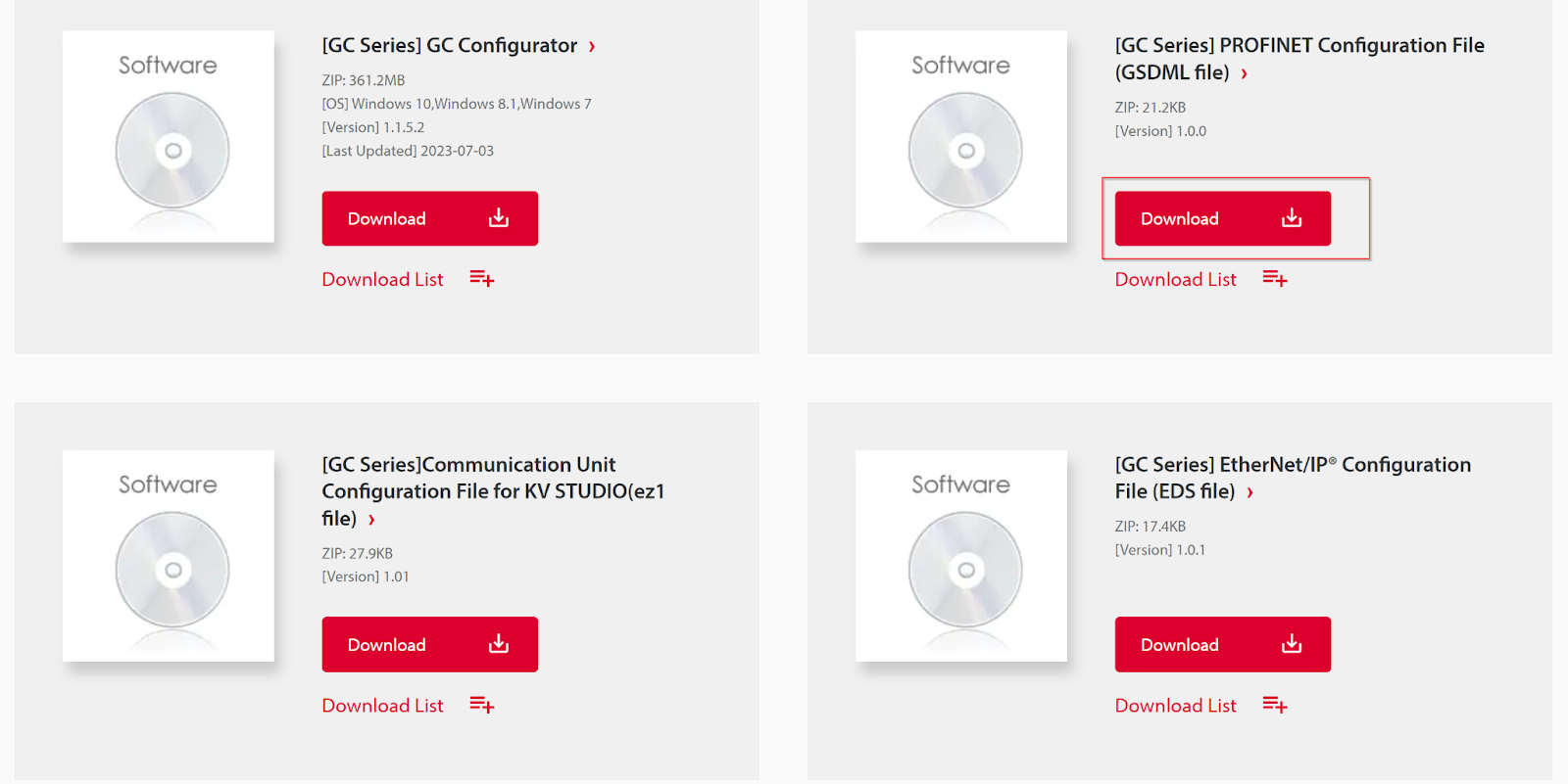
Download EDS File
Please download the EDS File of GC1000 from this Link.
https://www.keyence.com/products/safety/safety-controller/gc/downloads/?mode=so&modelId=PM_2691000
Implementation
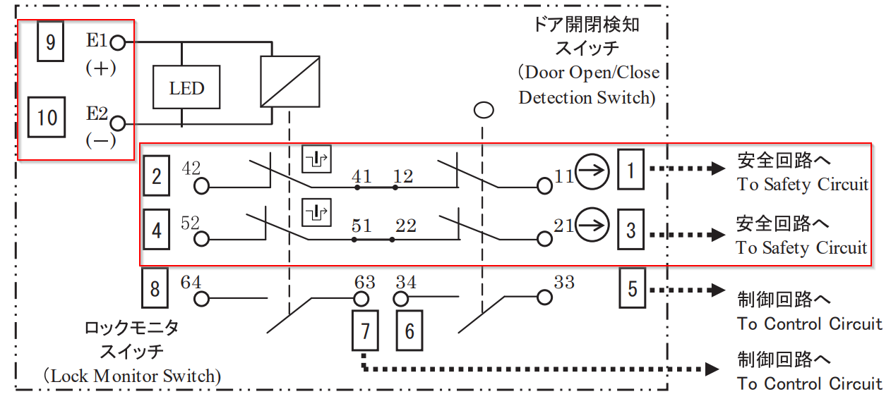
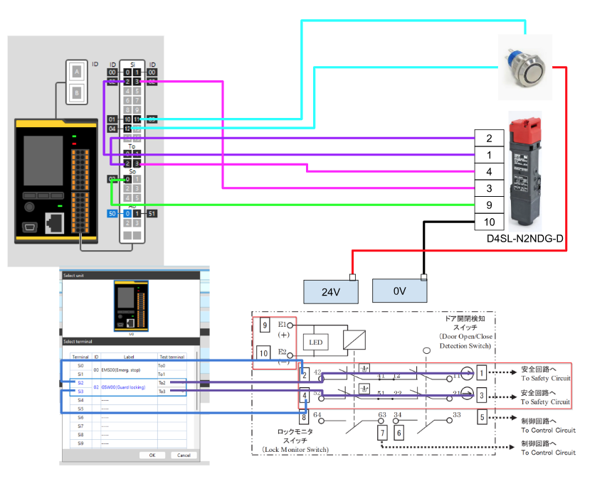
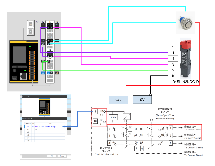
D4SL-N2NDG-D
Marked in red are the terminals that will be used in this case.
9,10 will be locked when 24v is present, and 2,1 and 4,3 will be Feedback for the lock signal.
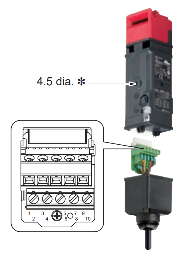
This is the terminal block type Omron door lock we will be using.
Wiring
This is Omron’s D4SL-N2NDG-D door lock, and also a Lock/Unlock input switch.
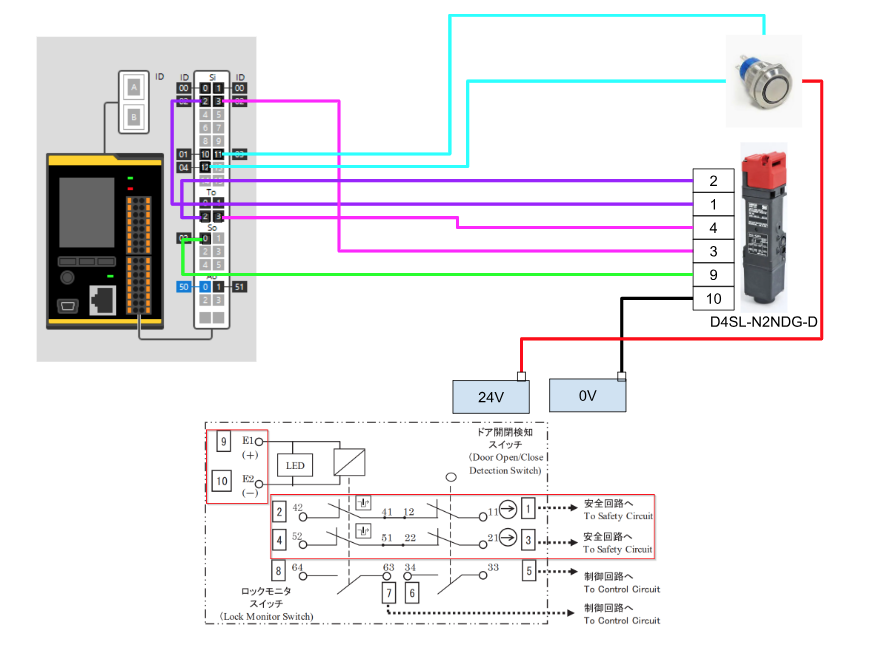
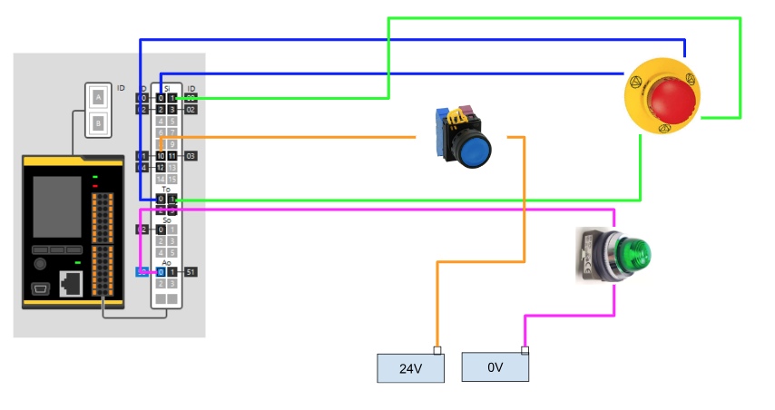
This is the same wiring for the emergency stop, lamp, and reset button as before.
Keyence Side
Configure the Ethernet/IP
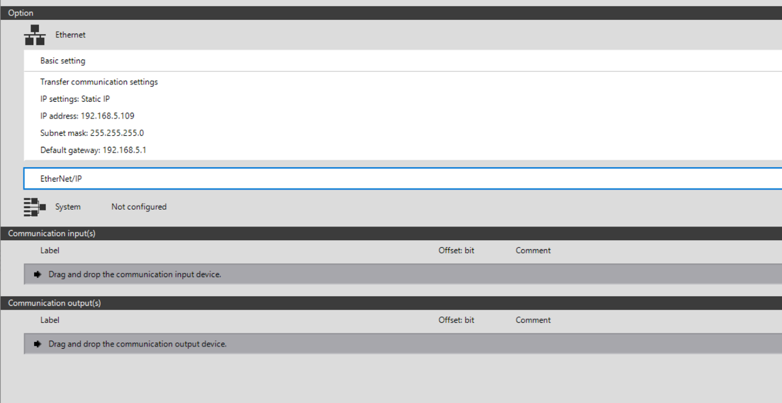
First, let’s put Option>Ethernet>Ethernet/IP into Ethernet in order to add Ethernet/IP Configuration to GC1000.
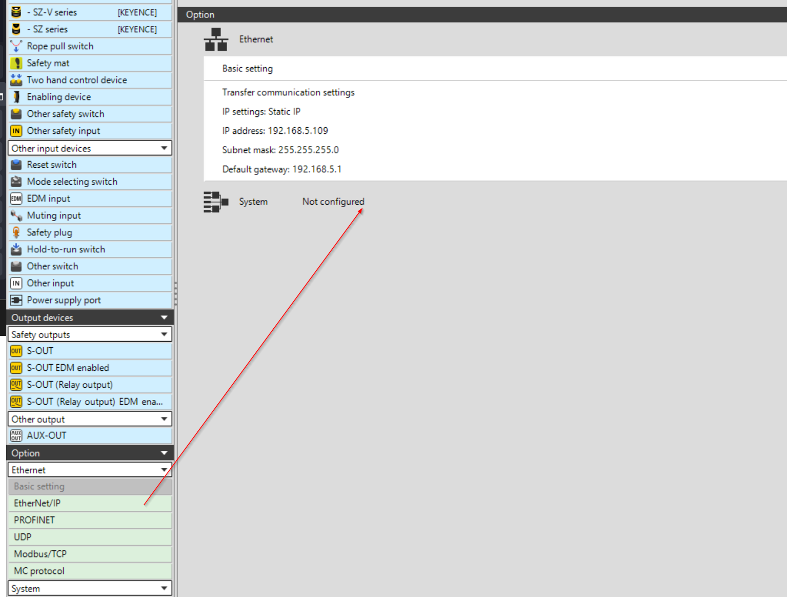
These areas where Ethernet/IP can be added will be pink.
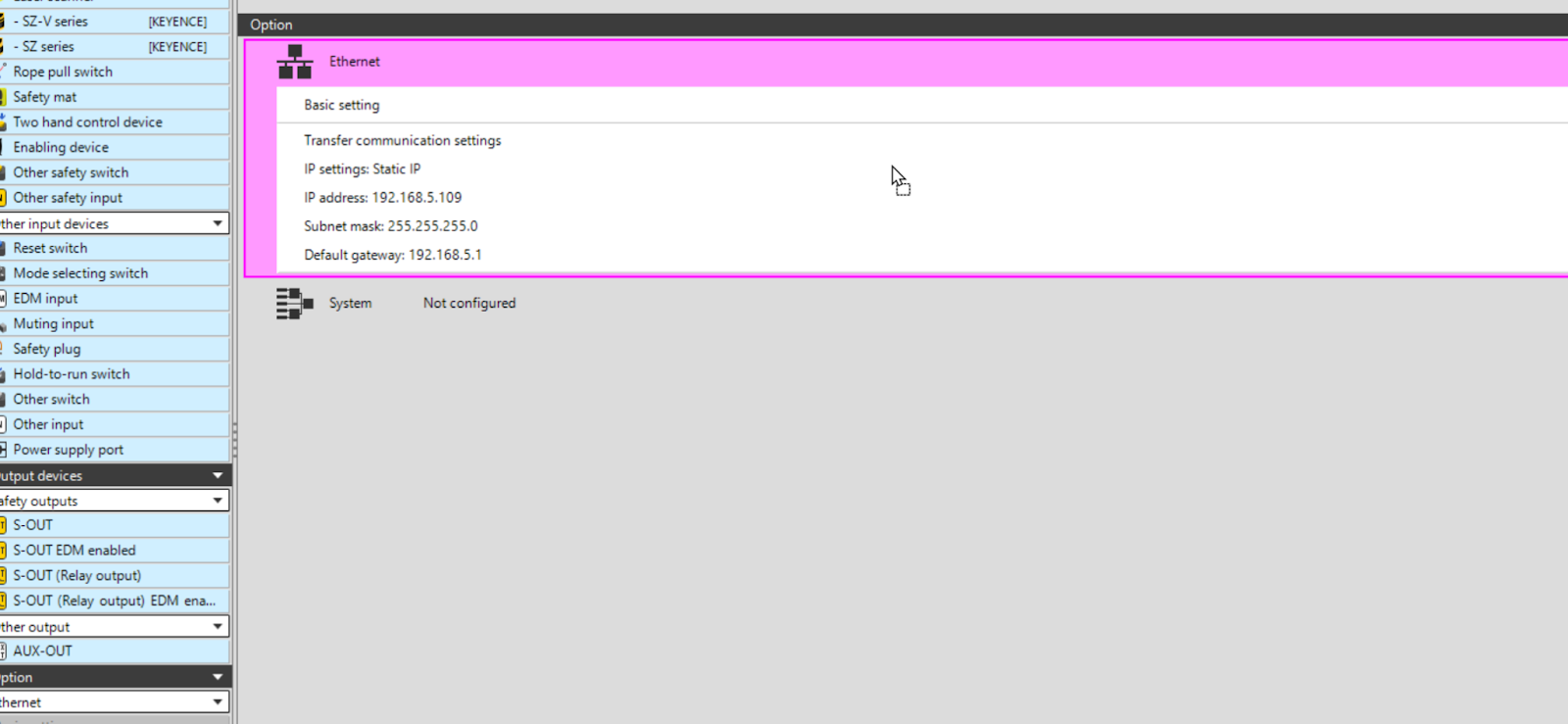
Done!
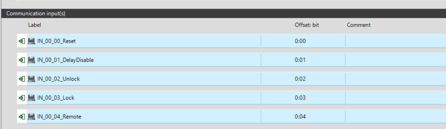
Configure INPUT
We need to define the Communication Input. This is the output of the WAGO PFC200.
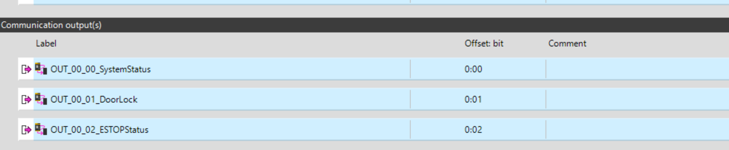
Configure OUTPUT
We need to define the Define Communication Output. This is the Input for the WAGO PFC200.
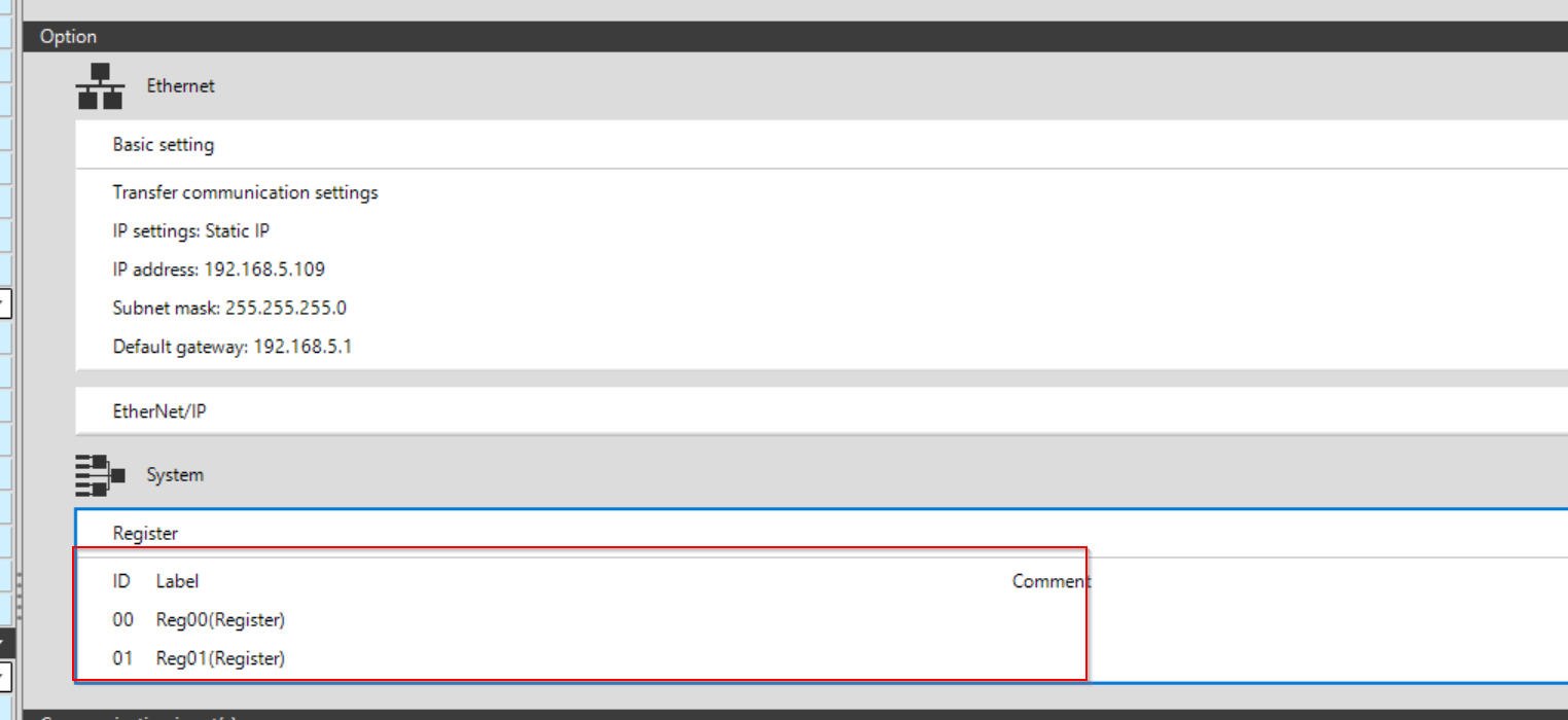
Configure Register
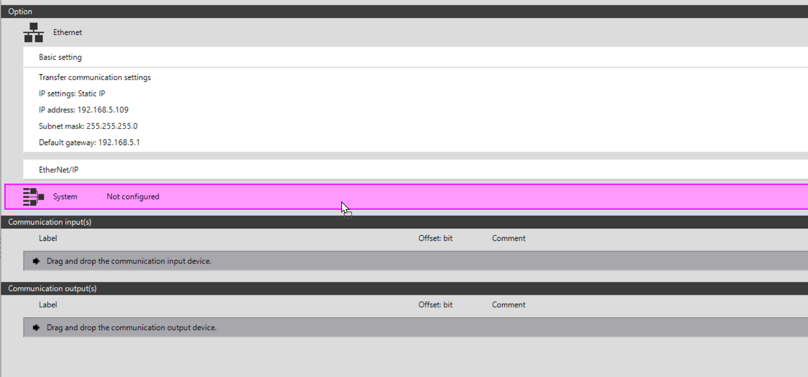
GC1000 can also use internal registers; add System>Register to the System section.
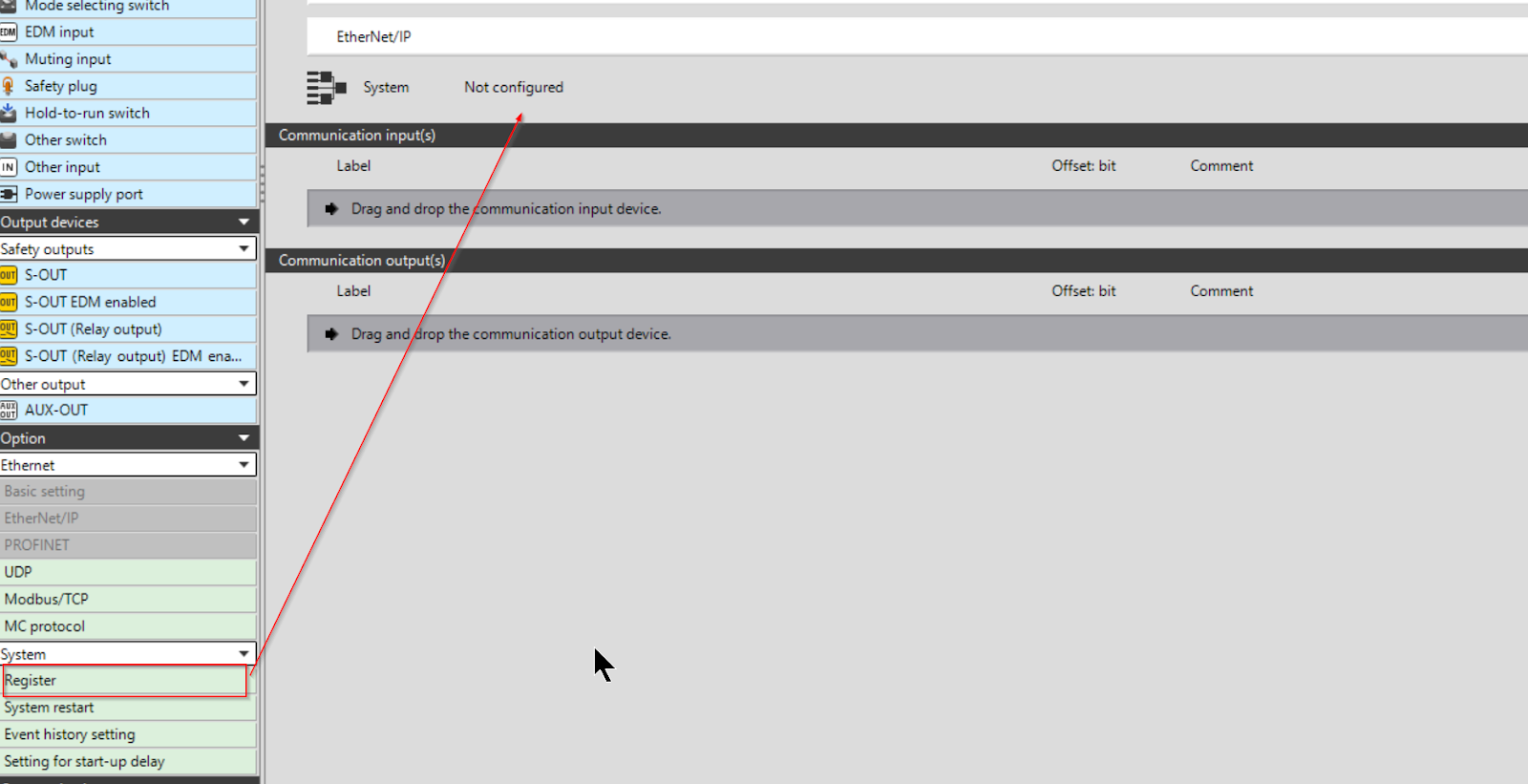
These areas where registers can be added will be pink.
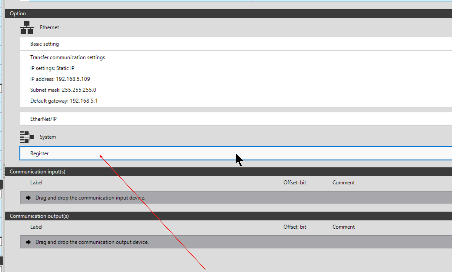
Done!
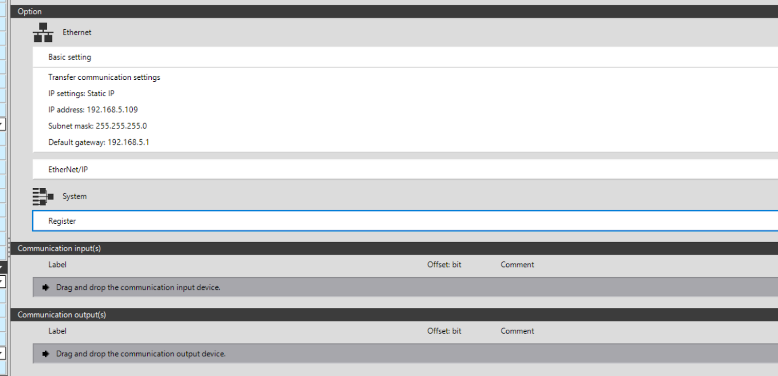
Next, double-click on Register.
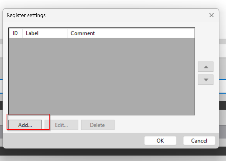
The Register settings screen appears.
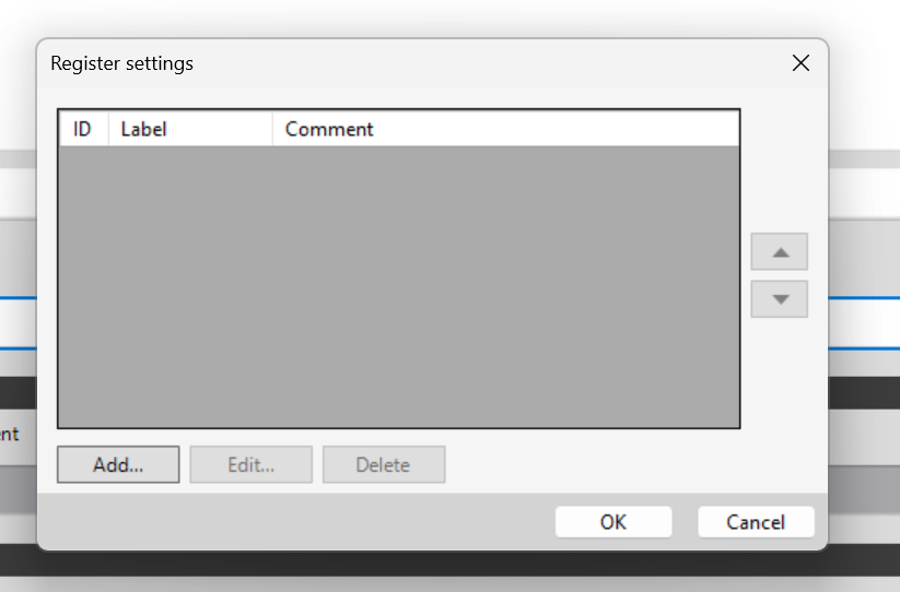
Click the Add button to add a new register.
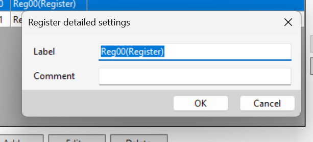
The Register detailed settings screen appears, where you can set labels and comments for each Register.
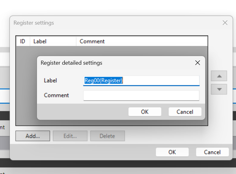
Done!
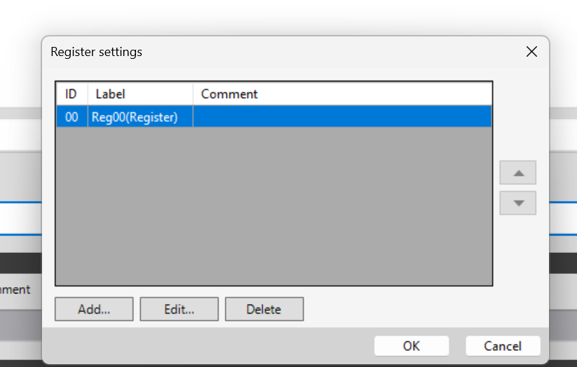
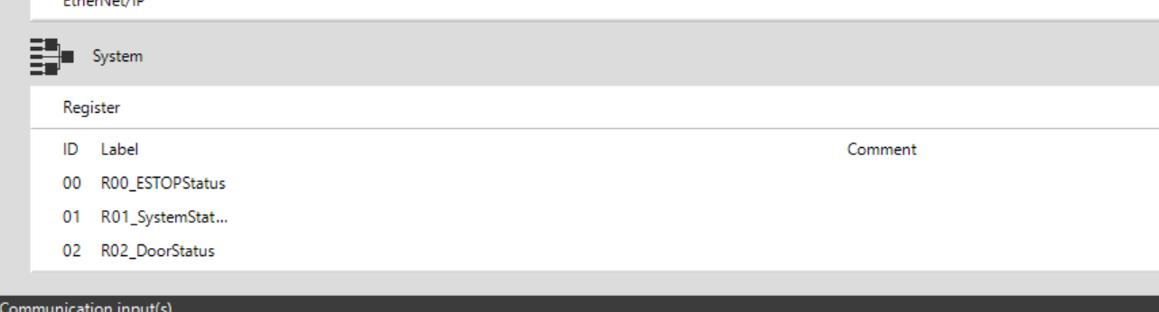
You can Declare multiple registers with the Add button.
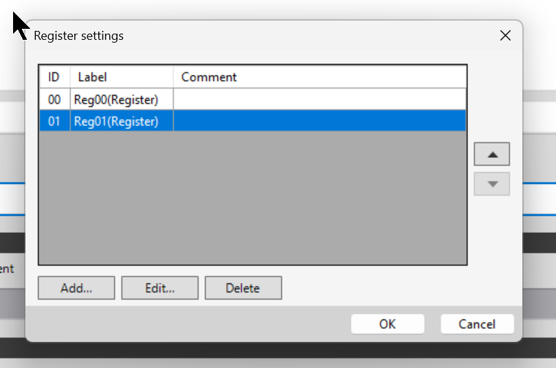
Done!Two internal registers were defined.
If you want to edit the currently defined register, click the Edit button.
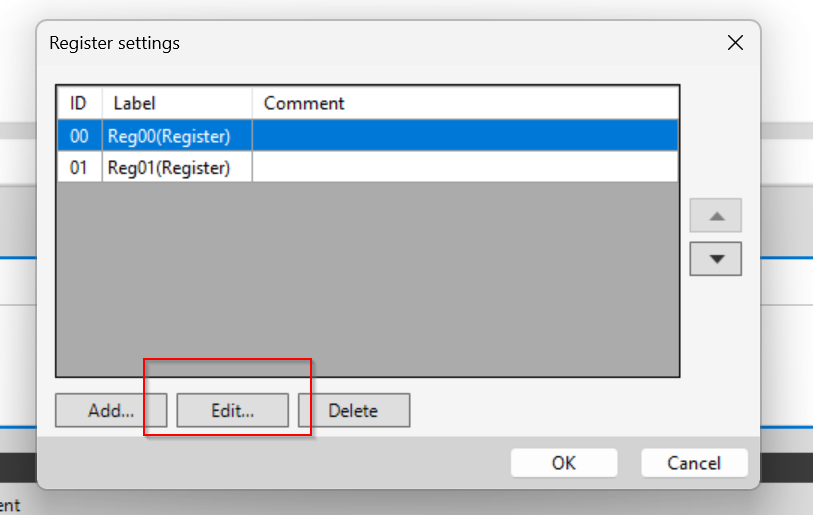
From there, register names and comments can be modified.
Done!
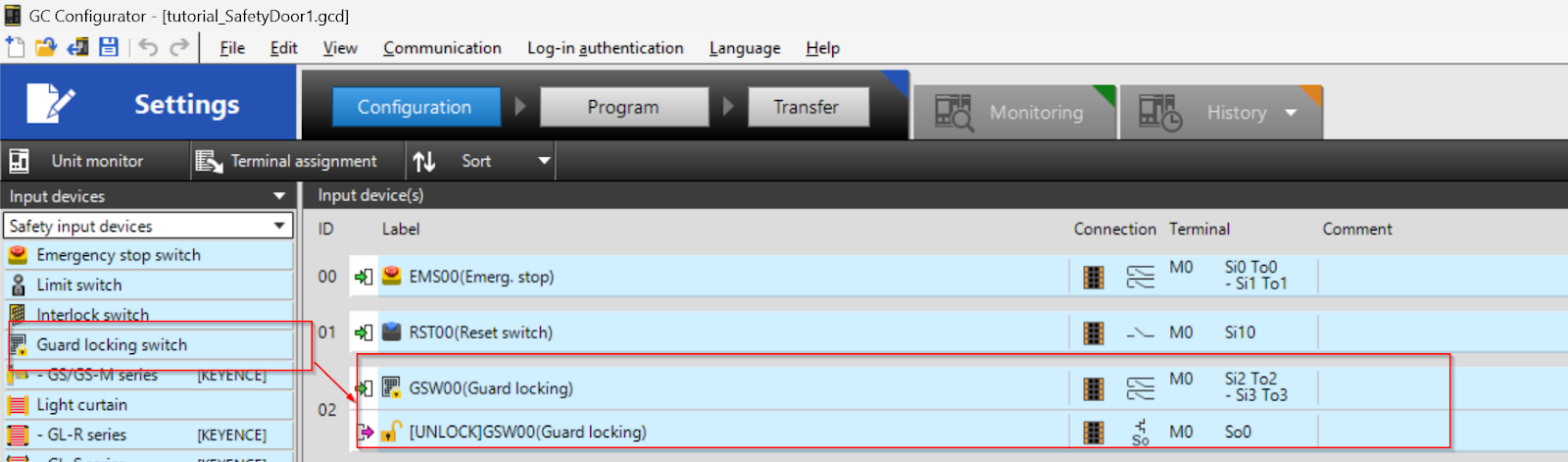
Configure the Door Switch
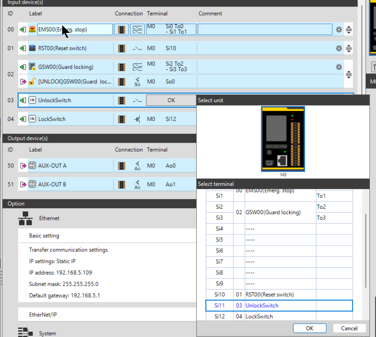
To add OMRON’s D4SL-N2NDG-D door lock to the project>Input devices>Safety input device>Guard locking switch to Input device(s).
Input Temrinal
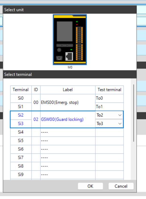
Next, click Terminal to set the wiring terminals.
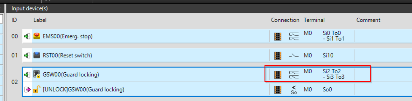
This time the D4SL-N2NDG-D door lock will be wired to terminal block Si2/Si3 and the Test terminal block to To2/To3.
A diagram of the relationship between the GC Configurator and the actual wiring is shown below.
Output Terminal
The next step is to set the output terminals. This terminal is wired to the door lock ON/OFF.
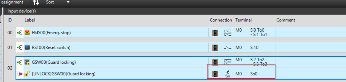
In this article, the output of the door lock is connected to So0.
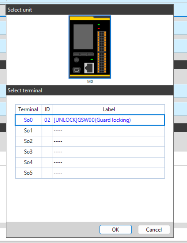
A diagram of the relationship between the GC Configurator and the actual wiring is shown below.
Unlock/Lock Switch
Now add two inputs from Other input. These two inputs are used by the operator to lock and unlock the door.
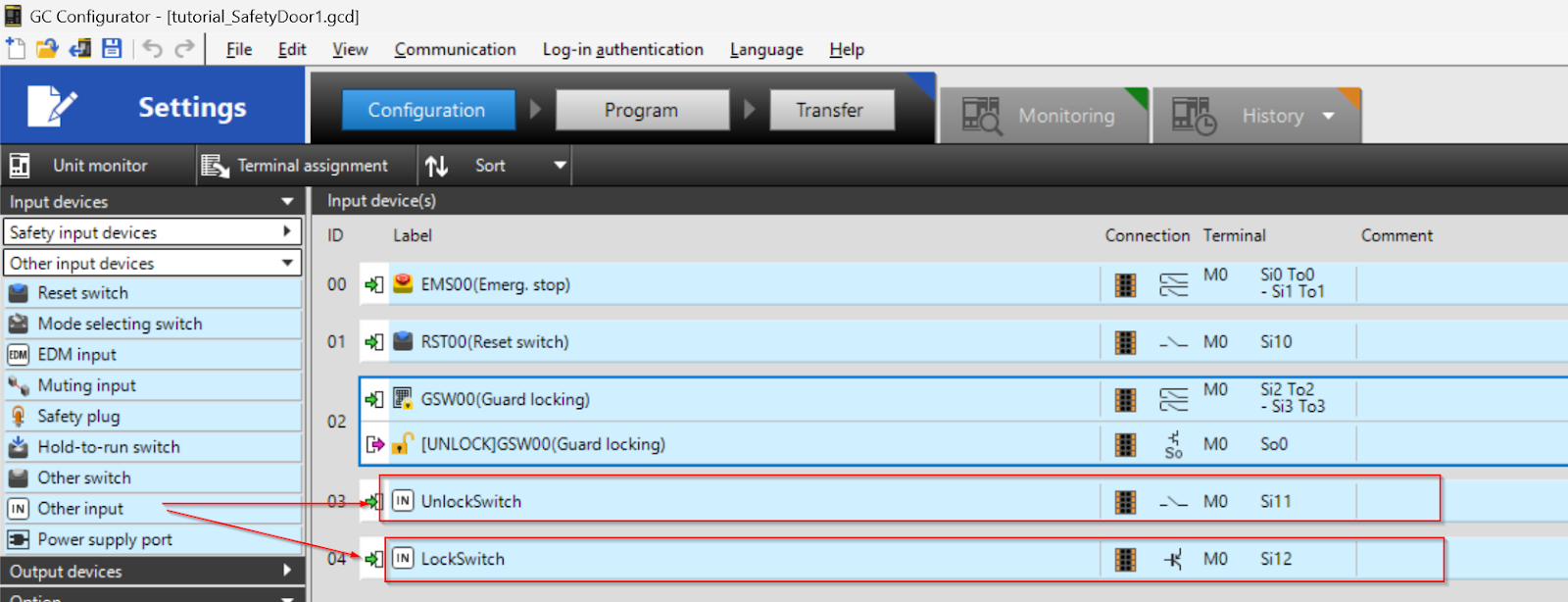
The Unlock/Lock switch is wired to Si11/Si12.
Program
We can create a safety program for GC1000. This time, it will be divided into ESTOP, DOOR, and Summary pages according to the safety function.
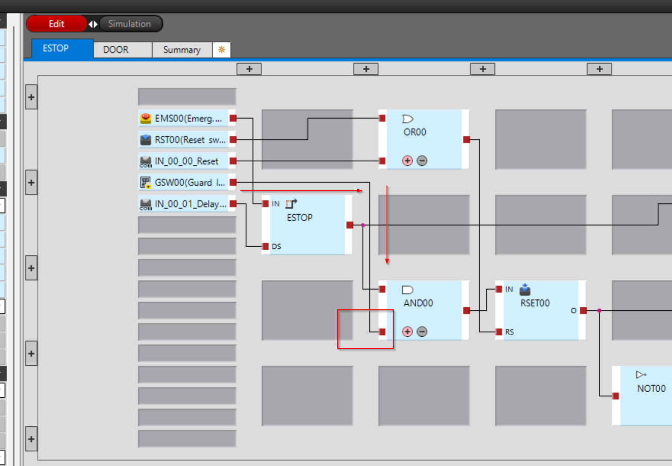
ESTOP
This is an emergency stop control program, and it’s almost the same as the last one.
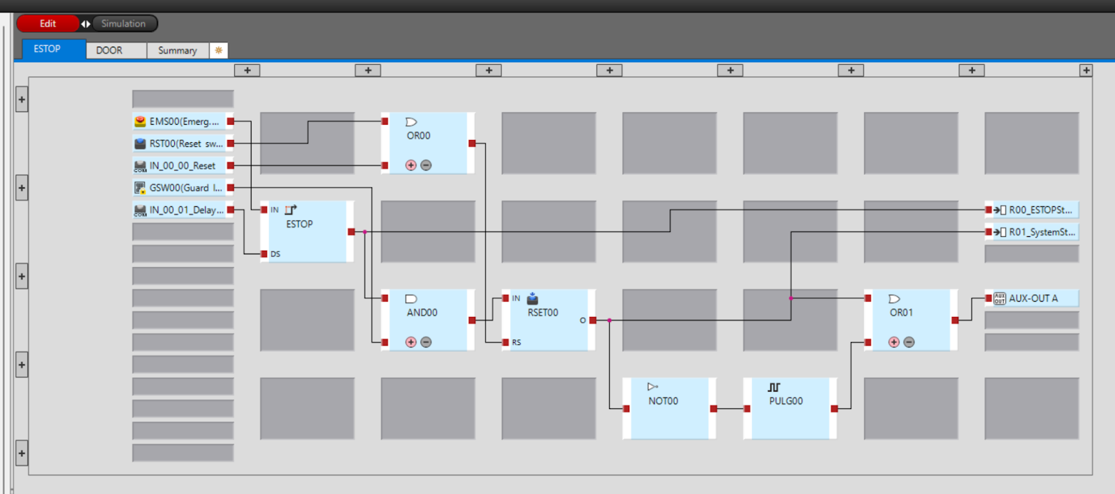
The INparma in the Block of RESET00 changes to the AND logic of the Door switch safety input and emergency stop.
The next step is to transfer the status of the emergency stop and RESET to the internal registers of the GC1000.

DOOR
This is a control program for Door lock.
The basic mode is divided into Remote and Local mode. In Remote mode, Door’s Unlock/Lock command is issued via Ethernet/IP, while in Local mode, Unlock/Lock operation is performed by the switch wired to the GC1000.
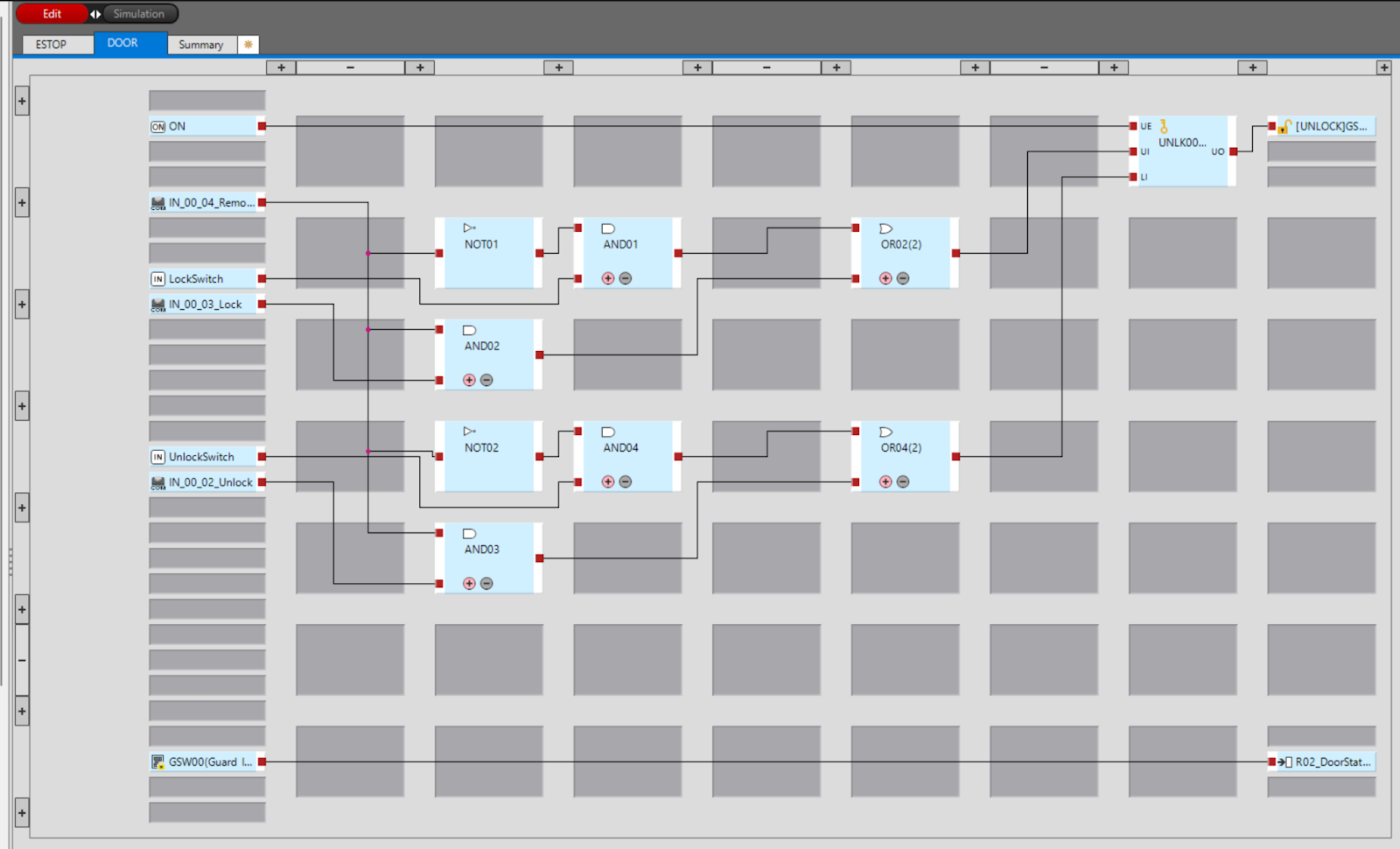
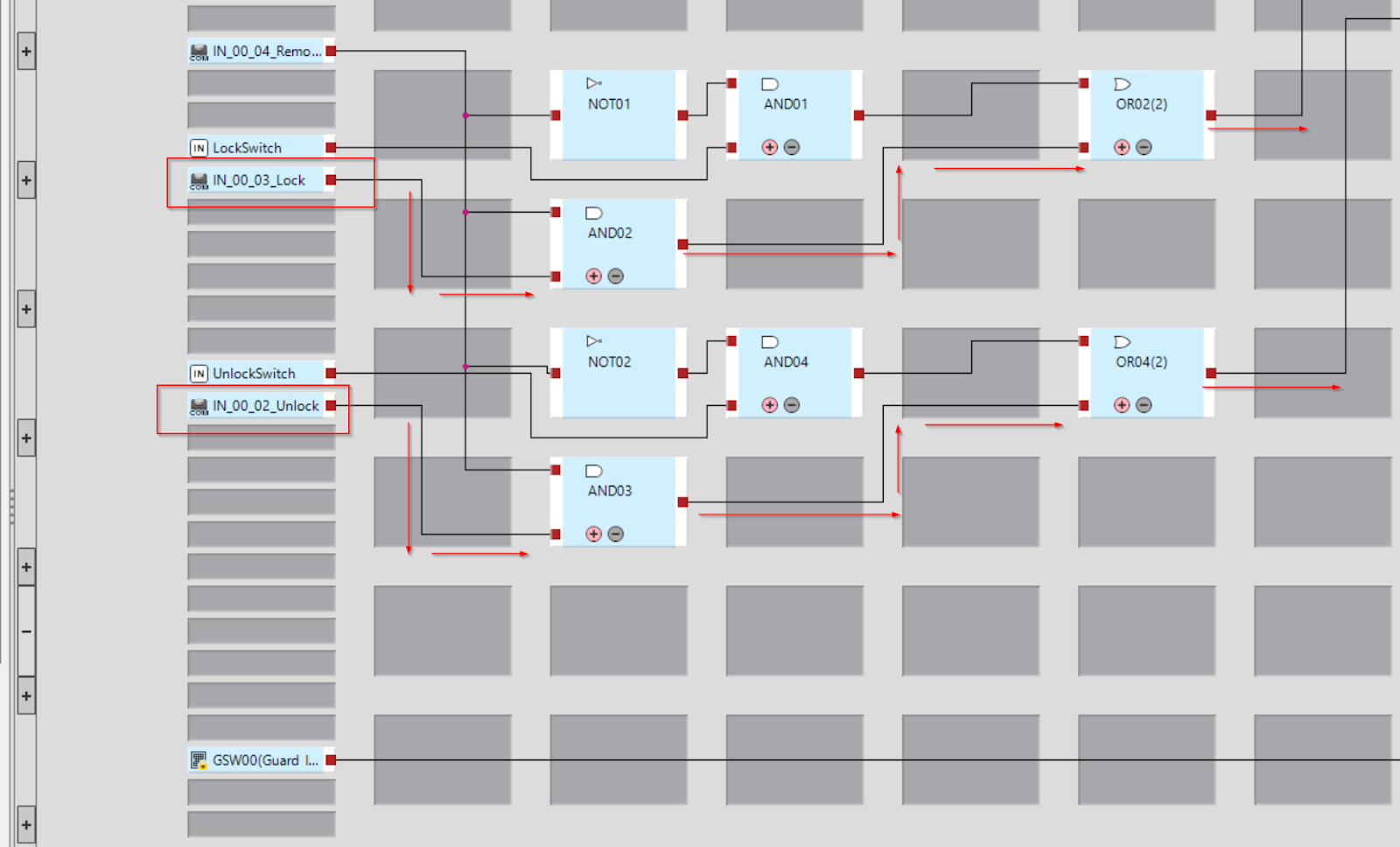
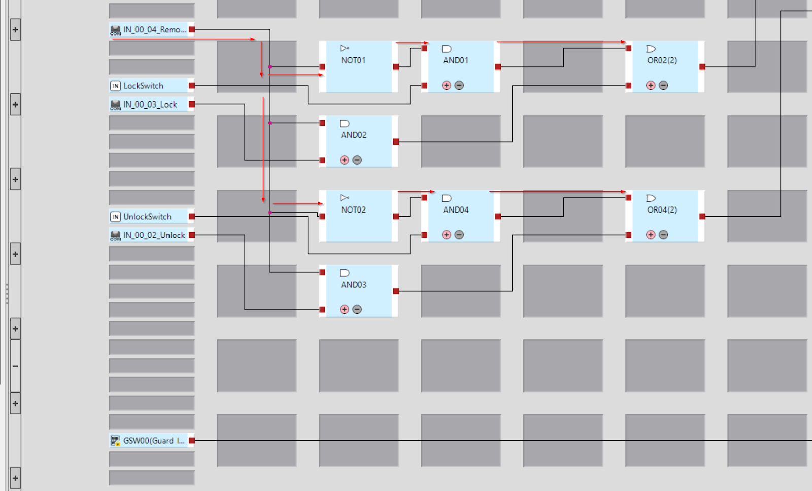
This is Remote mode control.
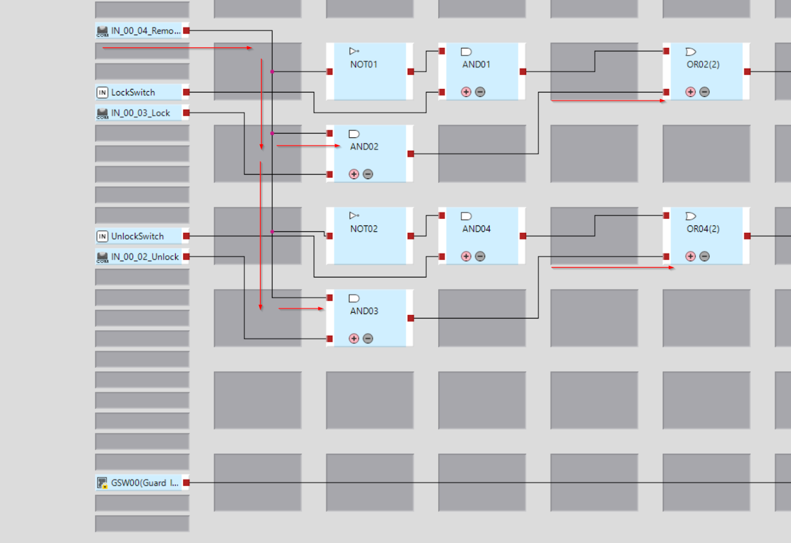
In Remote mode, Door’s Unlock/Lock commands are received from Ethernet/IP IN_00_01 and IN_00_02.
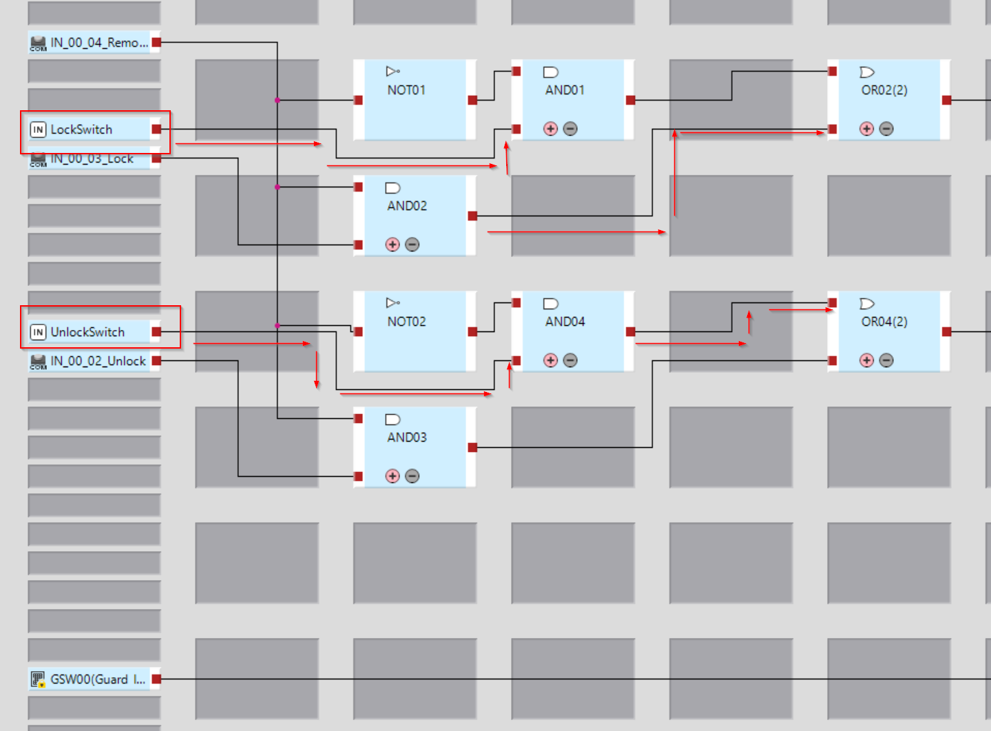
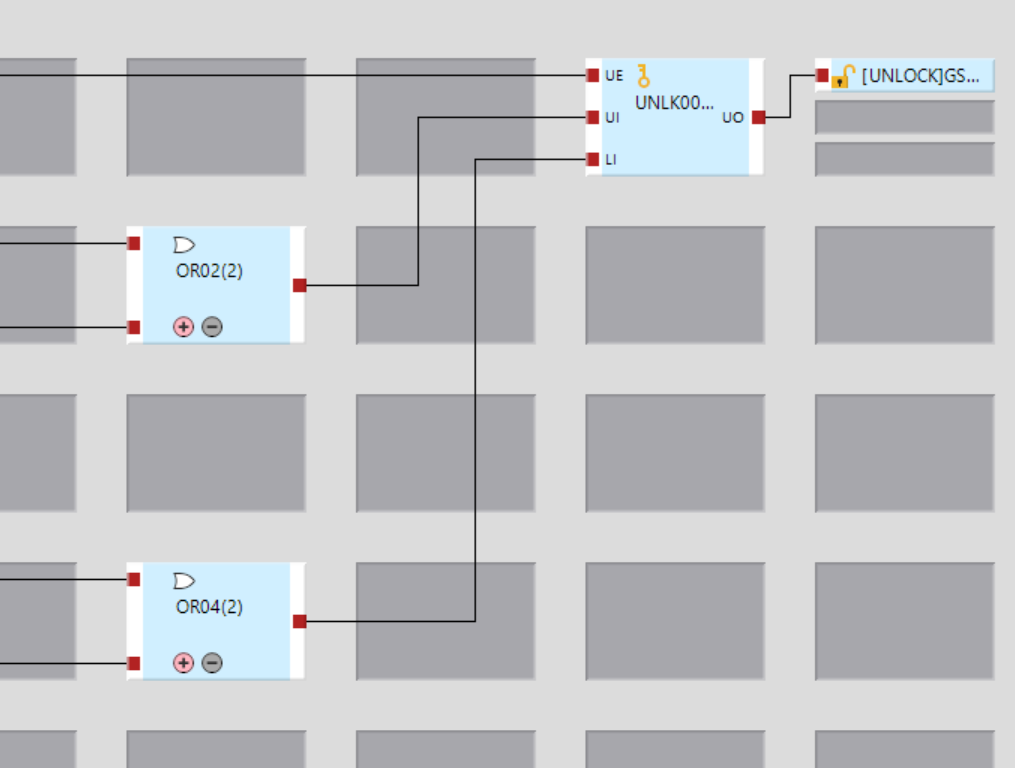
This is Local mode control.
In Local mode, Door’s Unlock/Lock command is received from the switch state.
The received Unlock/Lock command is passed over the UI/LI of the UNLK Block, and the UO is connected to the output of the Door lock.
Doorロックの接点をGC1000の内部レジスタに転送します。
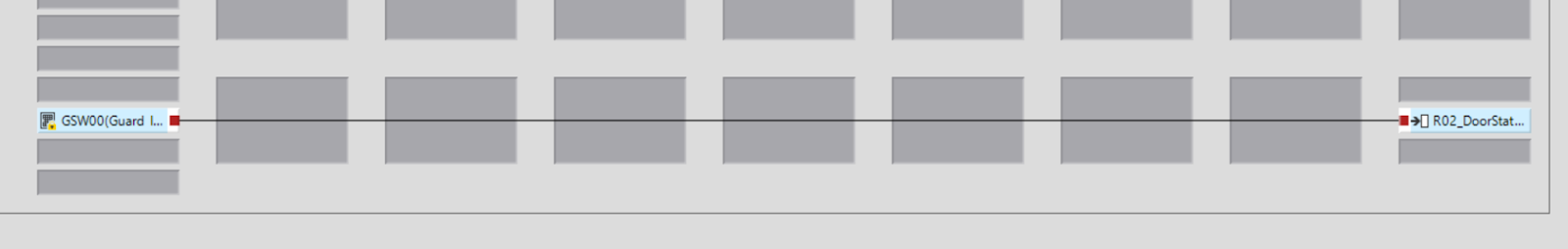
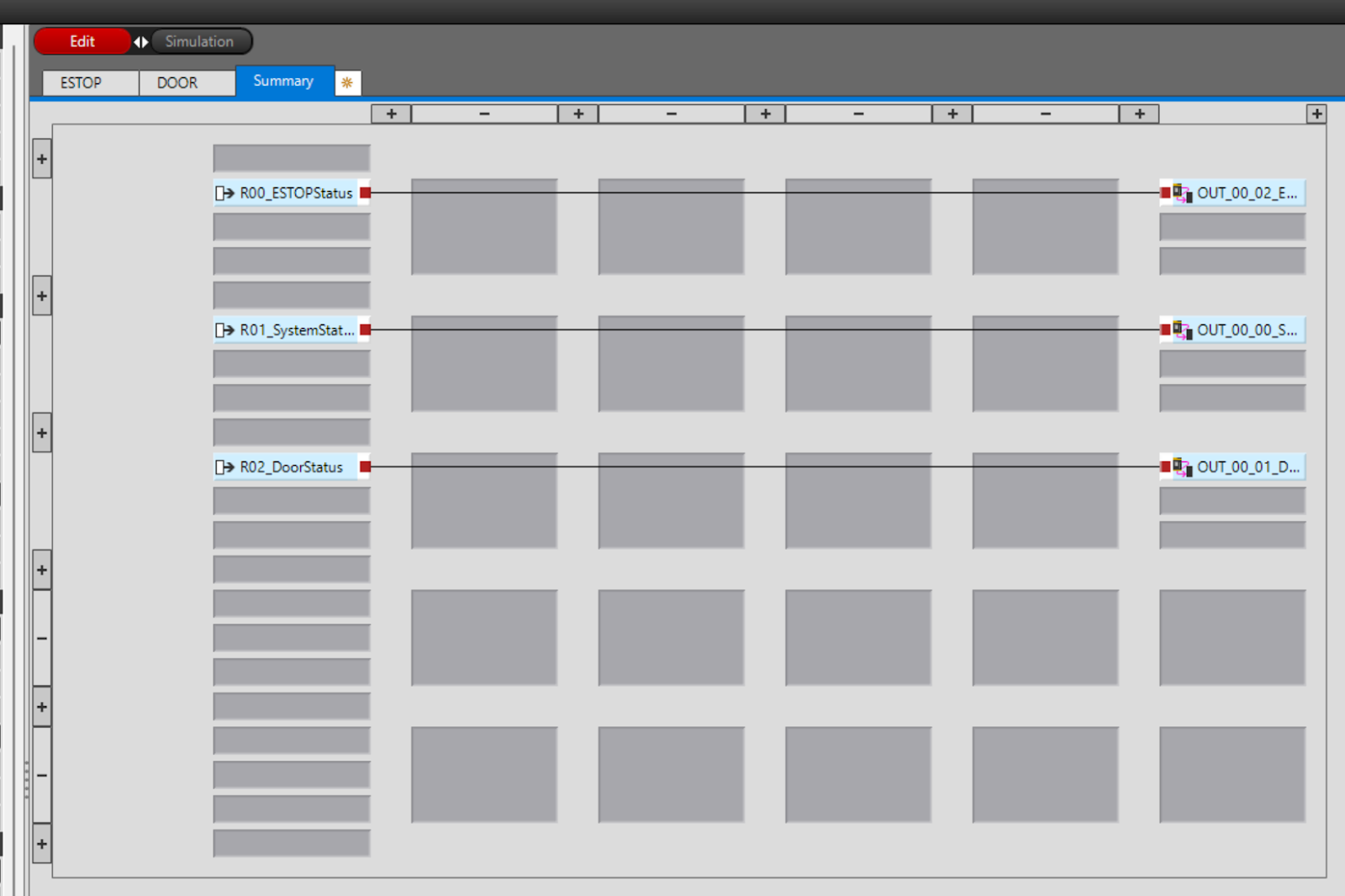
Summary
The final step is to output the GC1000’s internal registers to the Comm Output of Ethernet/IP.
Result
You can check the Unlock/Lock operation of the D4SL-N2NDG-D from this video.
Keyence.GC1000 Lock Unlock Door
You can see the D4SL-N2NDG-D Lock>Reset operation from this video.
Keyence.GC1000 Reset Status While Door is unlock and Resume
You can see the D4SL-N2NDG-D emergency stop release > reset operation from this video.
Keyence.GC1000 Reset Status While ESTOP is triggered
Wago Side
The next step is to build the Wago PFC200 side.
New Project
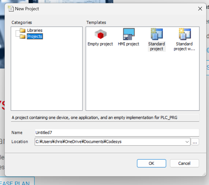
Create a new project at File>New Project.
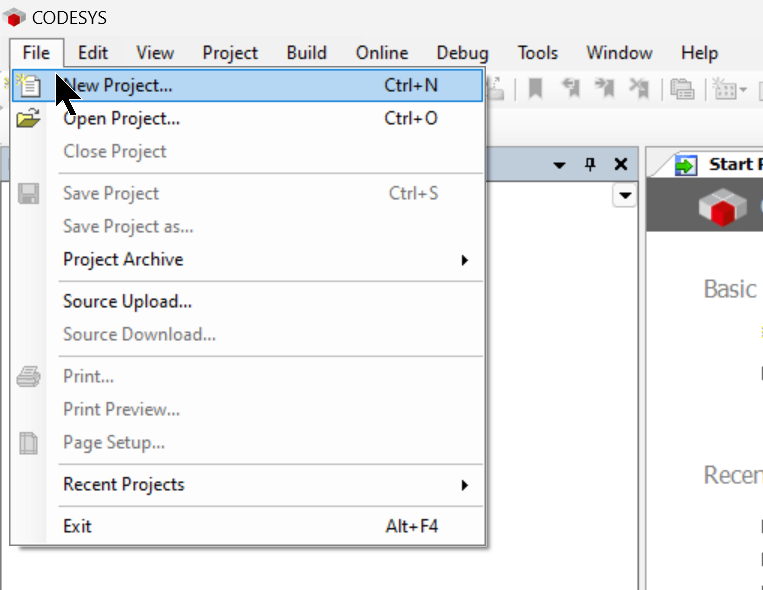
Select Standard Project for Templates and press Ok to proceed.
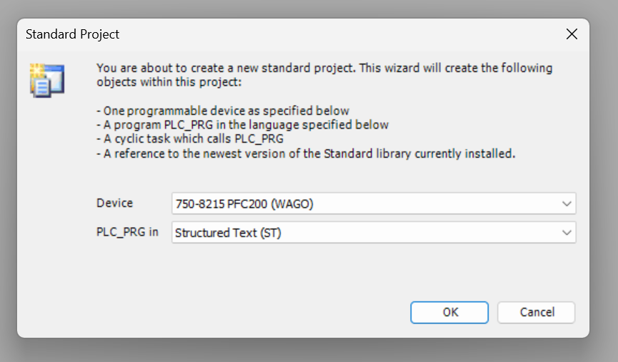
The Standard Project settings screen will appear.
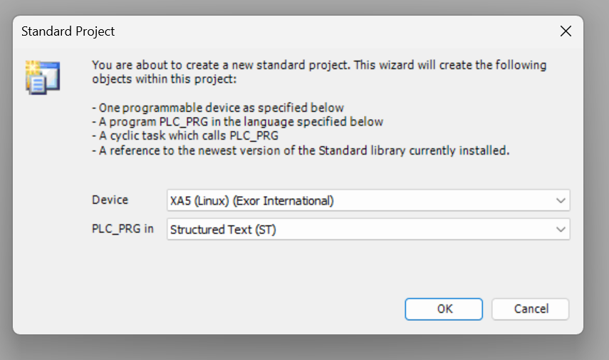
Set Device to 750-8215 PFC200 (WAGO) and proceed with OK.
Install the EDS File
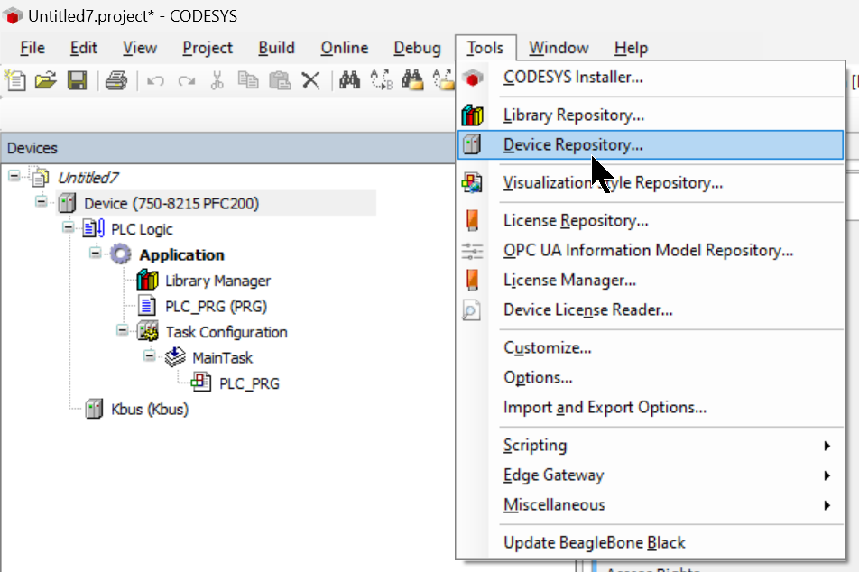
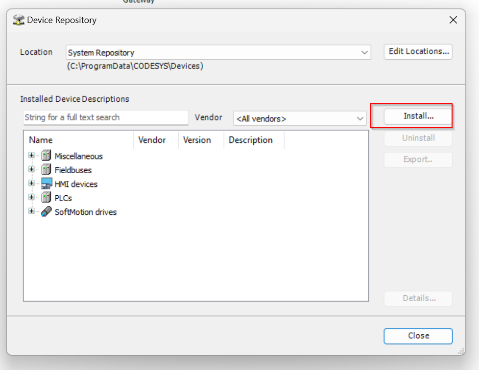
After creating a new project, now open Tools>Device Repository to install the GC1000 EDS File in the Codesys IDE.
The Device Repository screen appears and click the Install button.
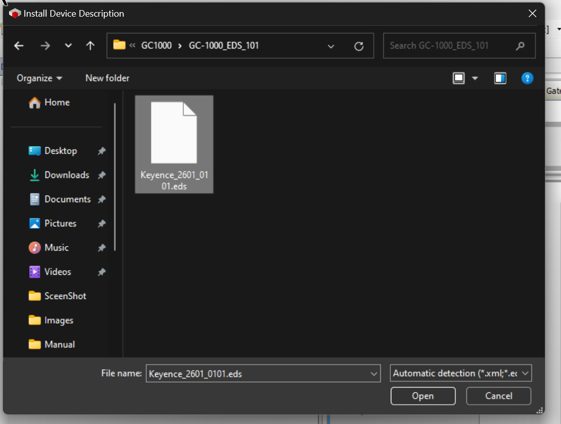
Open the EDS File you have just downloaded from the Keyence Web Site.
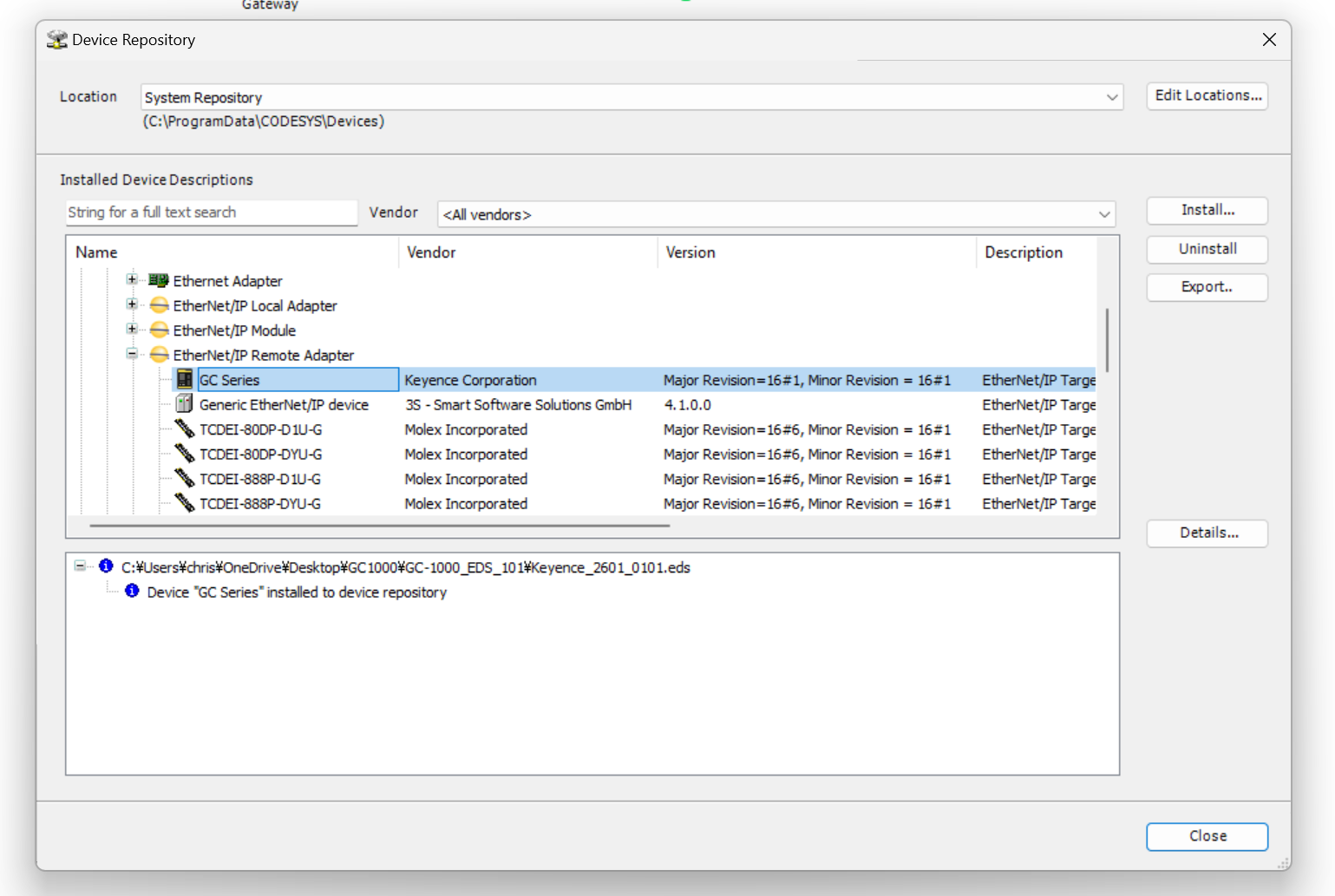
Done!EDS File for GC1000 has been installed.
Ethernet Adapter
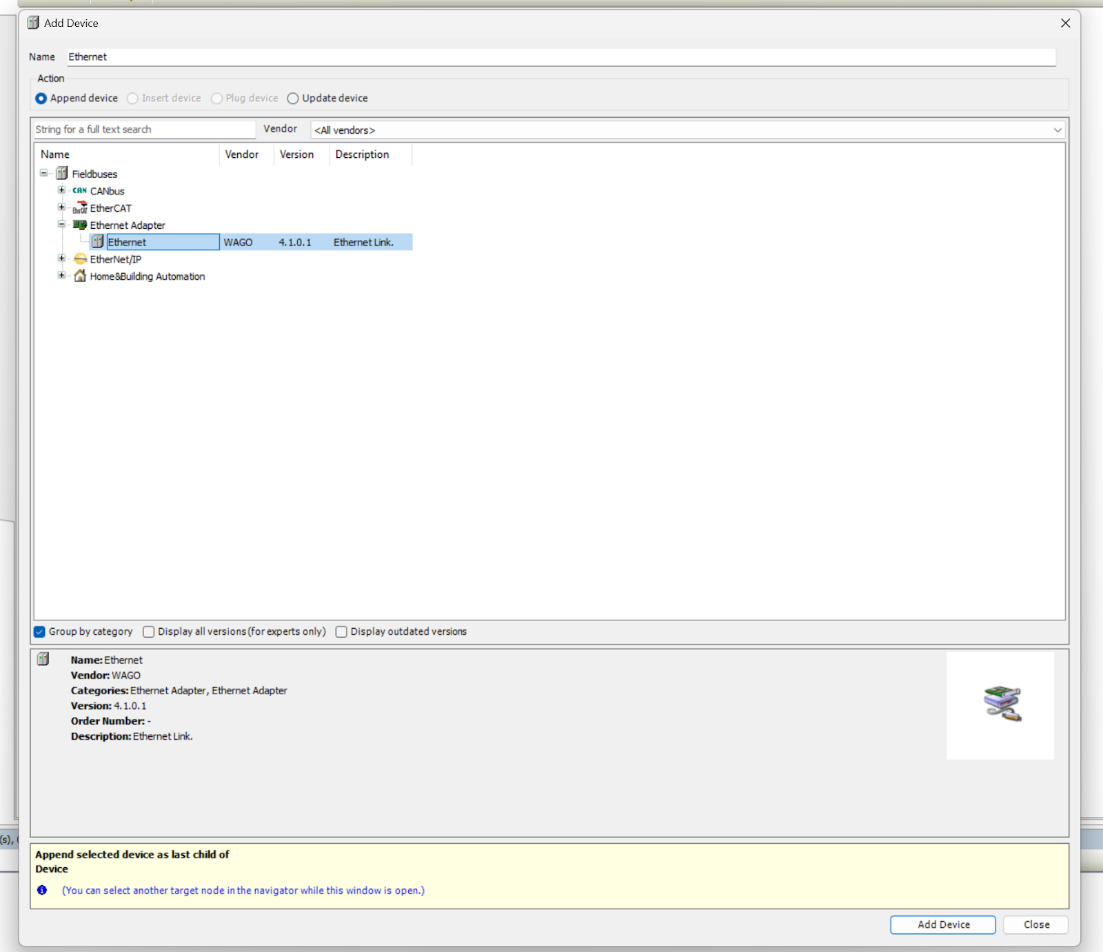
To build an Ethernet/IP Scanner in your Codesys project, you must first add an Ethernet/IP Adapter: right click on the Device>Add Device.
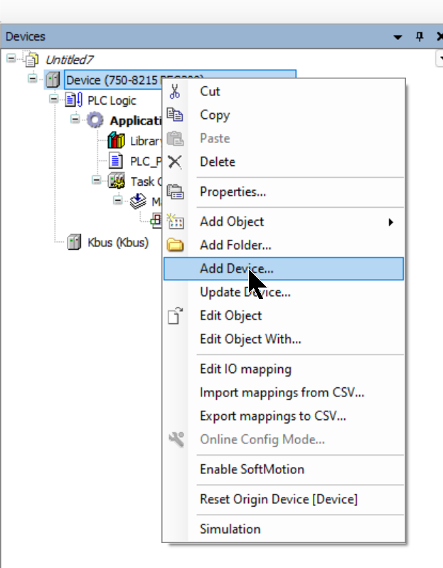
Add Ethernet Adapter>Ethernet.
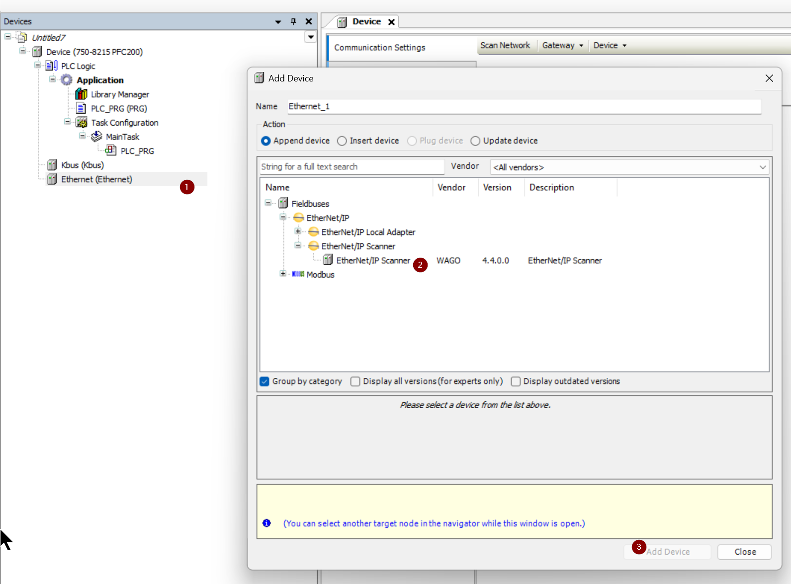
Ethernet/IP Scanner
Next, right click on Ethernet>Add Device>Ethernet/IP Scanner>Add Ethernet/IP Scanner.
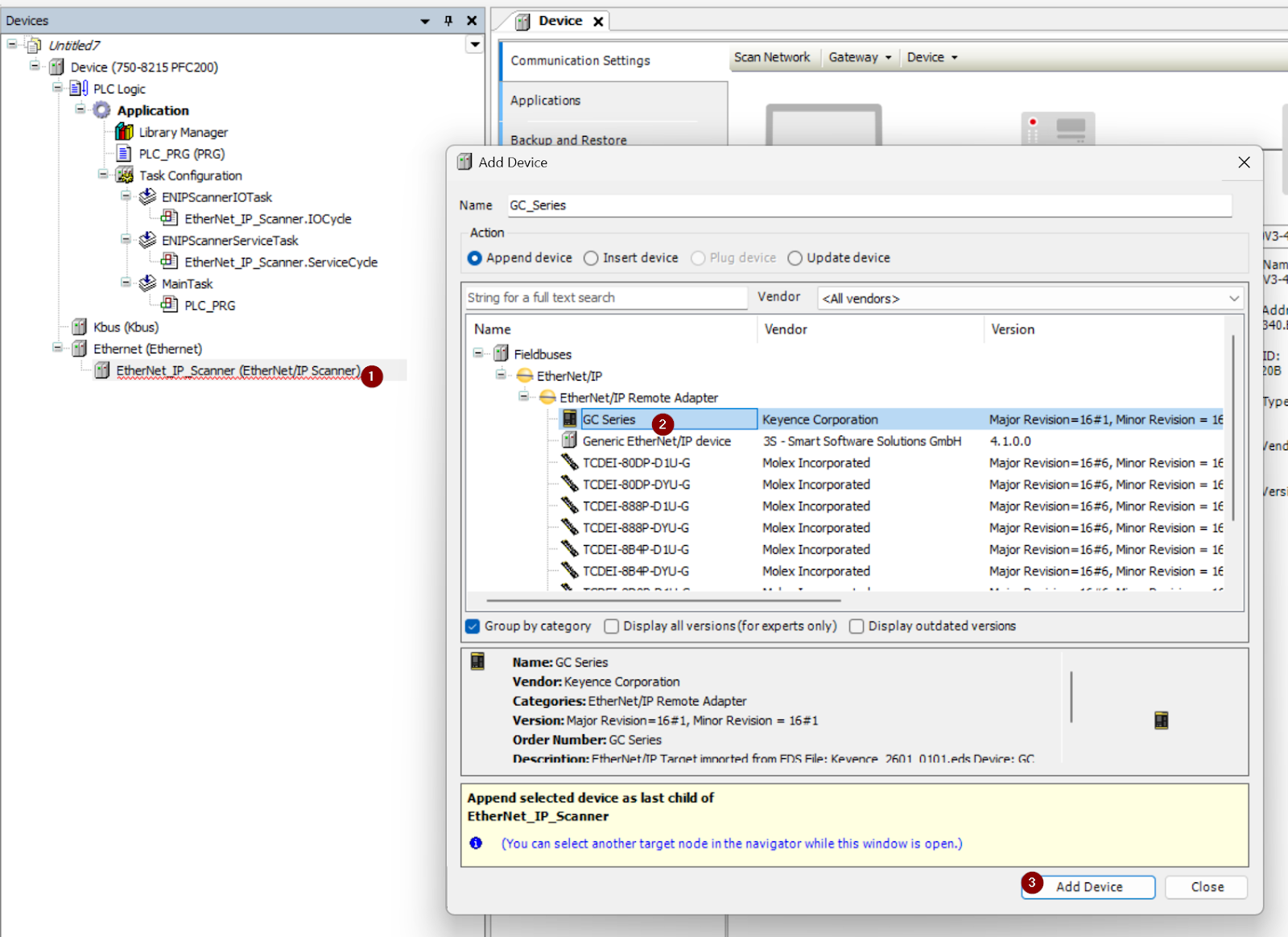
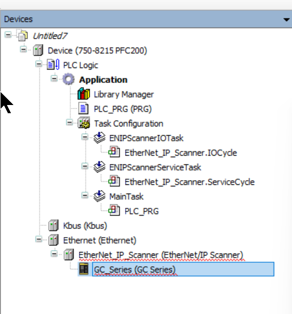
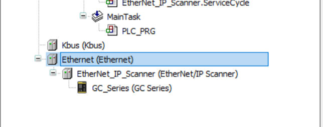
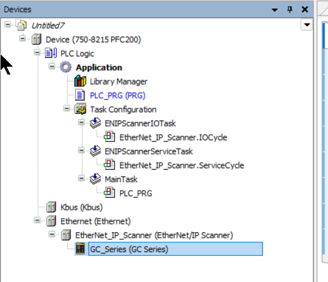
Add GC1000
Finally, add the Ethernet/IP Scanner you just added>Right click>Add Device>GC Series.
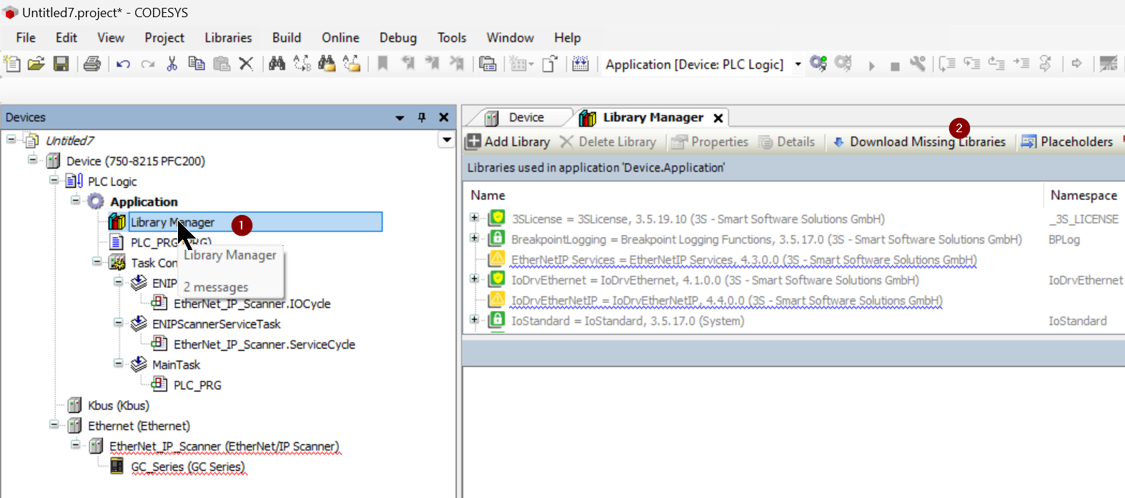
Download Missing Library
If you are new to Ethernet/IP use of WAGO’s PFC200 with Codesys, you will need to download the library.
Click on Library Manager>Download Missing Libraries.
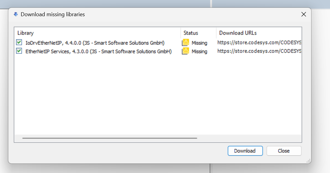
Check all the Library items and click “Download”.
Done!
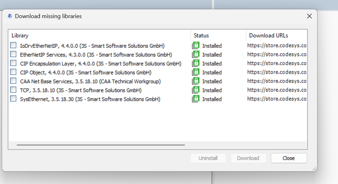
The Ethernet/IP Scanner Obejct no longer has the red line error. (If it still does not clear the error, try deleting the Ethernet/IP Scanner you have built and adding another one.)
Configure Ethernet
Double-click on Etherent.

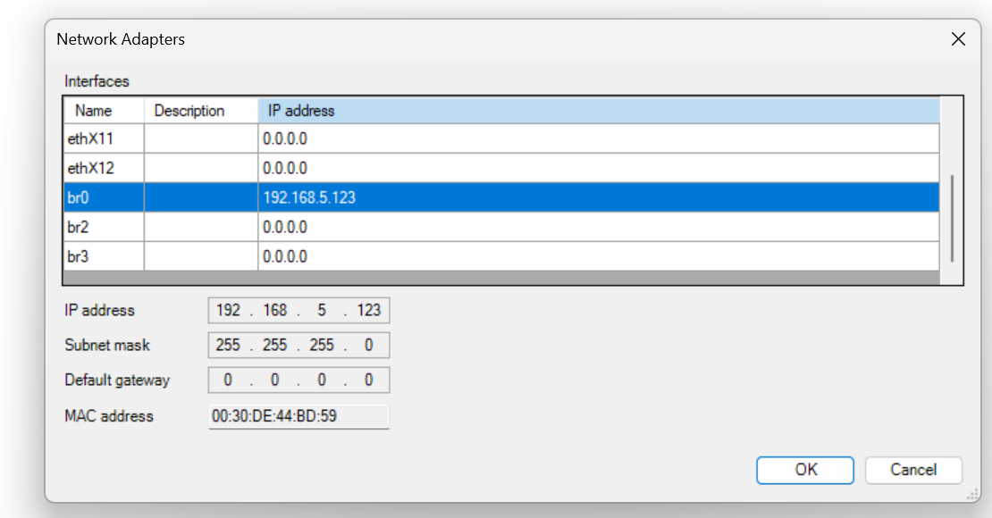
Click on the Browse button and set which Port of PFC200 of Wago is to be used for this Ethernet Interface.
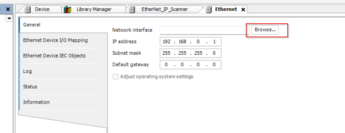
Select br0 192.168.5.123 and >Ok.
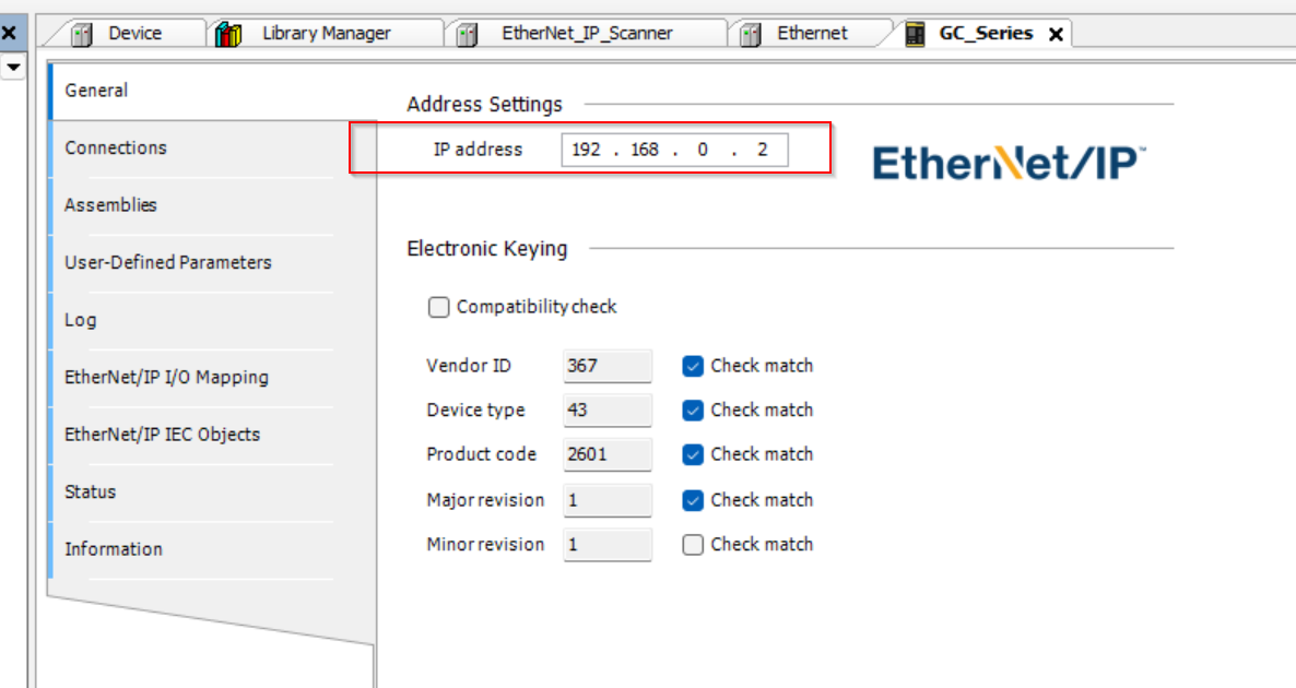
Configure GC1000
The next step is to configure the Ethernet/IP Adapter settings for the Keyence GC1000.
Put the IP of GC1000 in the IP address field.
Program
The next step is to make the program.
DUT
u2ByteToWord
This is a 2Bytes and Word UNION Data Type.
| TYPE u2ByteToWord : UNION _data:ARRAY[0..1]OF BYTE; OperationTime:WORD; END_UNION END_TYPE |
DUT_GC1000_Status
This is a structure that summarizes the data sent and received by GC1000.
| TYPE DUT_GC1000_Status : STRUCT iCommunicationInput :ARRAY[0..3]OF WORD; qCommunicationOutput :ARRAY[0..3]OF WORD; iNumberOfExpansionUnit :UINT; iNumberOfRemoteModule :UINT; OpertingTime :u2ByteToWord; OperationStatus :UINT; NumberOfErrors :UINT; GCLinkPortStatus :UINT; END_STRUCT END_TYPE |
GVL
In the Global Variable List, define variables with the DUT_GC1000_Status you just created.
| {attribute ‘qualified_only’} VAR_GLOBAL GC1000:DUT_GC1000_Status; END_VAR |
MAIN
The final step is to create a program that receives emergency stop, door lock status, etc., and operates the remote lock, unlock, and reset.
| PROGRAM PLC_PRG VAR GC1000_SystemStatus ,GC1000_DoorLock ,GC1000_ESTOPStatus:BOOL; GC1000_Reset ,GC1000_DelayDisable ,GC1000_DoorUnlockCommand ,GC1000_DoorlockCommand ,GC1000_Remote :BOOL; END_VAR GC1000_SystemStatus:=GVL.GC1000.iCommunicationInput[0].0; GC1000_DoorLock:=GVL.GC1000.iCommunicationInput[0].1; GC1000_ESTOPStatus:=GVL.GC1000.iCommunicationInput[0].2; GVL.GC1000.qCommunicationOutput[0].0:=GC1000_Reset; GVL.GC1000.qCommunicationOutput[0].1:=GC1000_DelayDisable; GVL.GC1000.qCommunicationOutput[0].2:=GC1000_DoorUnlockCommand AND GC1000_Remote ; GVL.GC1000.qCommunicationOutput[0].3:=GC1000_DoorlockCommand AND GC1000_Remote ; GVL.GC1000.qCommunicationOutput[0].4:=GC1000_Remote; |
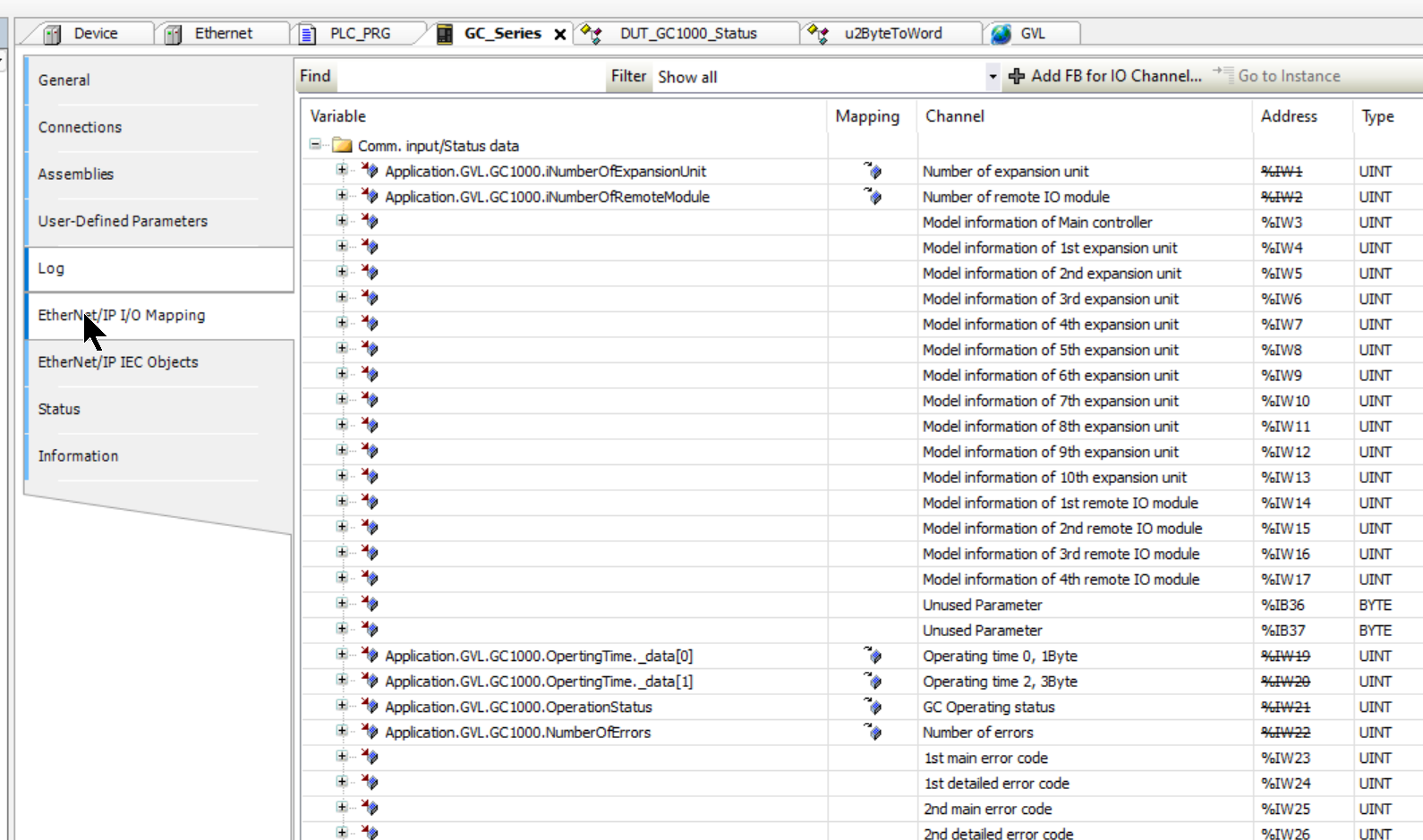
Mapping
Let’s use GC1000>Ethernet/IP I/O Mapping to map program variables and Process IO.
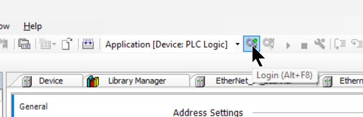
Login
Click the Login button to download the project.
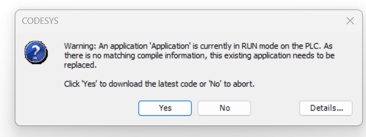
Proceed with Yes.
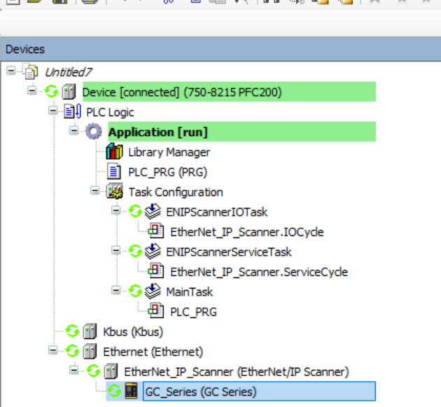
Start
Click the Start button to run the program.

Result
Here is a video of resetting GC1000 from WAGO PFC200 via Ethenret/IP.
Keyence.GC1000 ESTOP Staus Send to WAGO PLC with EtherentIP
Here is a video of the WAGO GC1000 sending the normal status to the WAGO PFC200 via Ethernet/IP.
Keyence.GC1000 Normal Staus Send to WAGO PLC with EtherentIP
Here is a video of locking and unlocking the D4SL-N2NDG-D from the WAGO PFC200 via Ethenret/IP.
Keyence.GC1000 Door Lock Unlock Command Receive From WAGO PLC with EtherentIP
Download
You can download the article Codesys and GC1000 project from this link.
https://github.com/soup01Threes/Codesys/blob/main/Tutorial_GC1000_wagoPFC200_EIP.7z