This article describes how to establish a CIP Safety and Ethernet/IP connection to a Turck TBIP-L5-4FDI-4FDX using an OMRON NX102-1220 in combination with an SL5700, and how to set up Turck’s Safety EDS Fie programme from scratch. We explain how to set up the Turck Safety EDS File from scratch.
Let’s get started!

Reference Video
OMRON.Let’s Connect with Turck’s CIP Safety IO
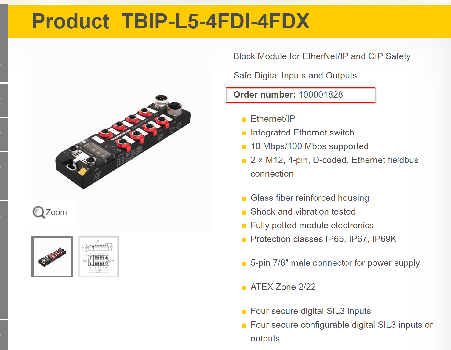
TBIP−L5−4FDI−4FDX?
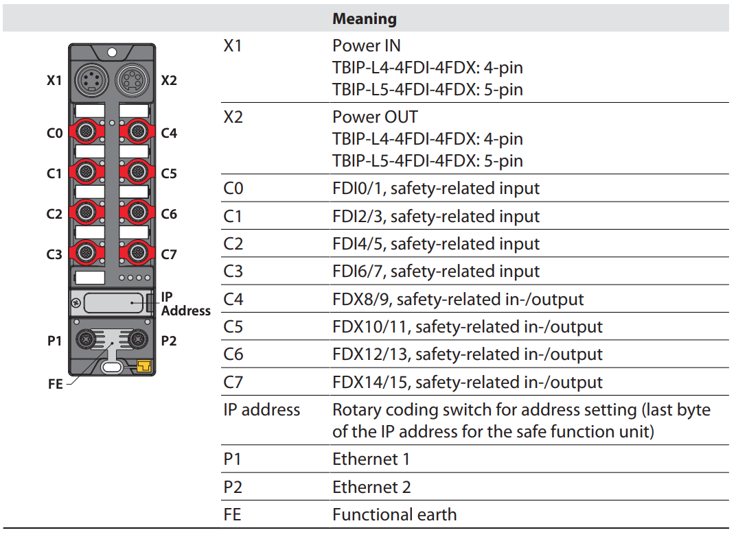
TBIP-L… The -4FDI-4FDX is a safety block I/O module for CIP Safety via EtherNet/IP. The device has four 2-channel digital safety inputs (FDI) for connecting different safety sensors such as light barriers or emergency stop buttons. A further four safety channels (FDX) can be freely used as inputs (FDI) or outputs (FDO).
The safety I/Os and their functions are also configured with the software tool Turck Safety Configurator.
TBIP-L… -4FDI-4FDX has eight M12 connectors for connecting safe sensors and actuators. For connecting the supply voltage, a 4-pin 7/8” connector (TBIP-L4), a 5-pin 7/8” connector (TBIPL5) or a 5-pin L-code M12 connector (TBIP-LL) is available.
IP Addressing
TBIP-L… -4FDI-4FDX supports two IP addresses and whether a secondary IP address is required depends on the application used and the CIP Safety Scanner.
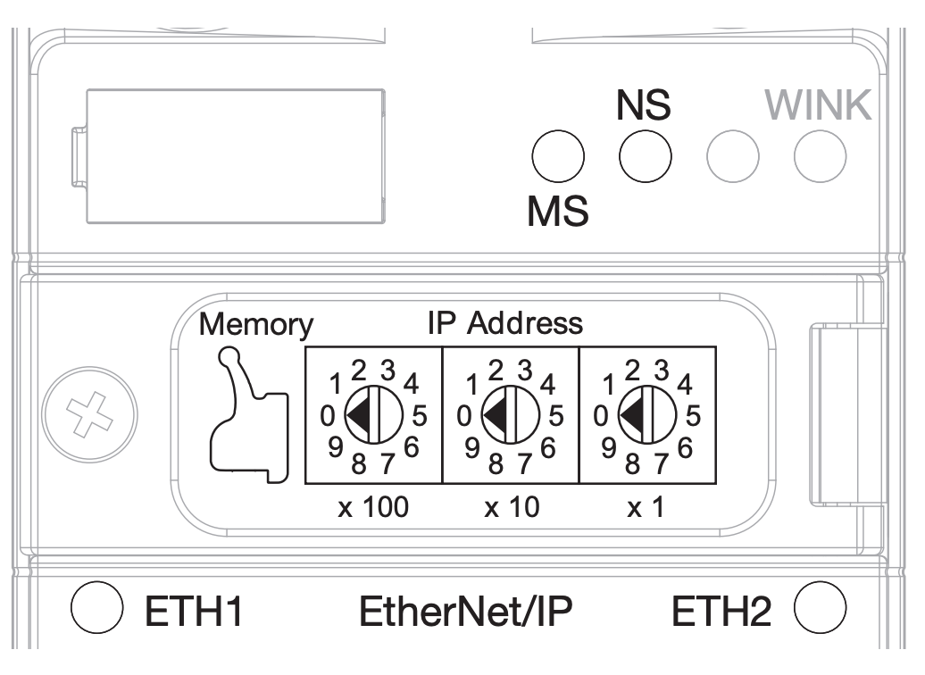
The first three bytes of the main IP address can be set via the instrument’s web server (Default state is IP address: 192.168.1.254) The last byte of the IP address The main IP address can be set via the instrument’s rotary code switch, Turck Service Tool or It can be set via the web server.
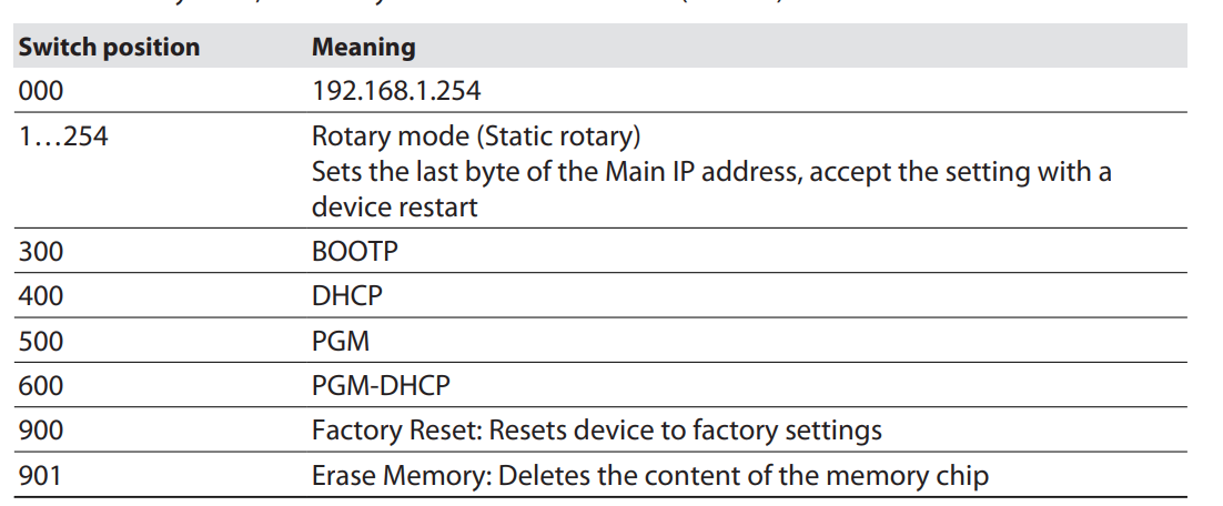
This is the meaning of the rotary code switch.
Input Data
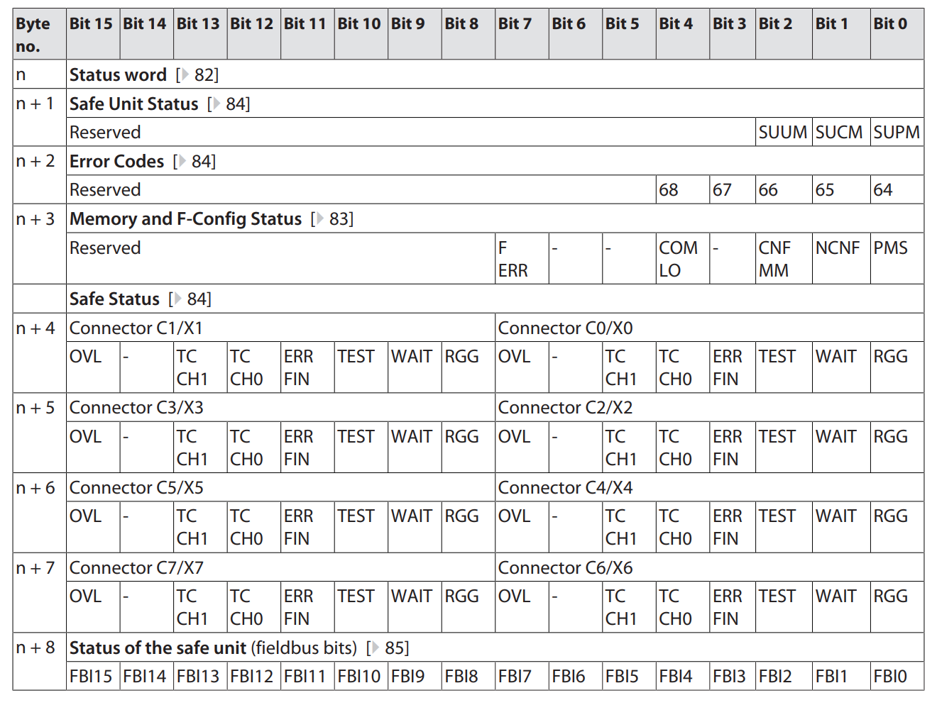
This is the input data Mapping for the Ethernet/IP Connection.
Output Data
This is the output data Mapping of the Ethernet/IP Connection.
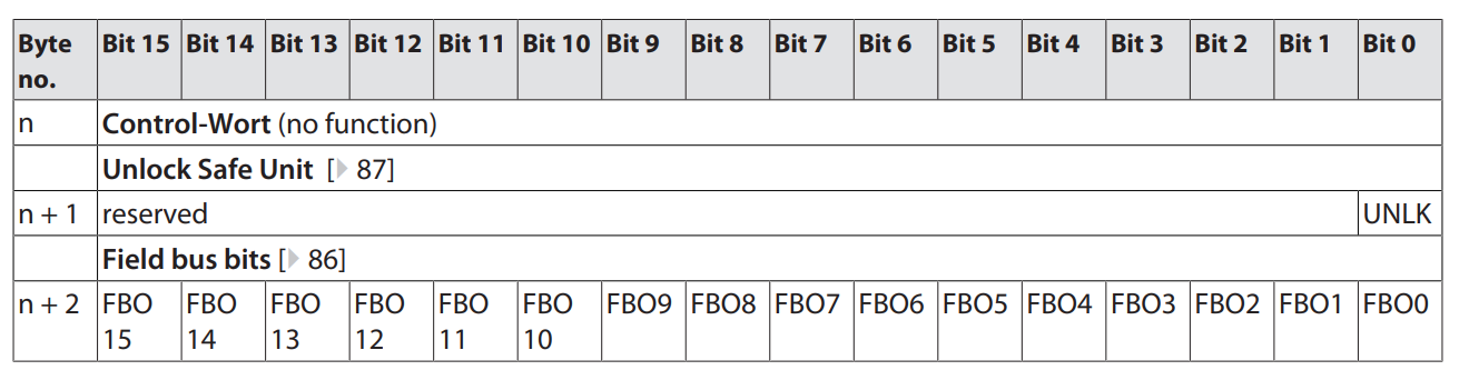
Unlock Safe Unit
The Bit signal to unlock the safe unit is responded to by a falling edge.
Implementation
Turck Side
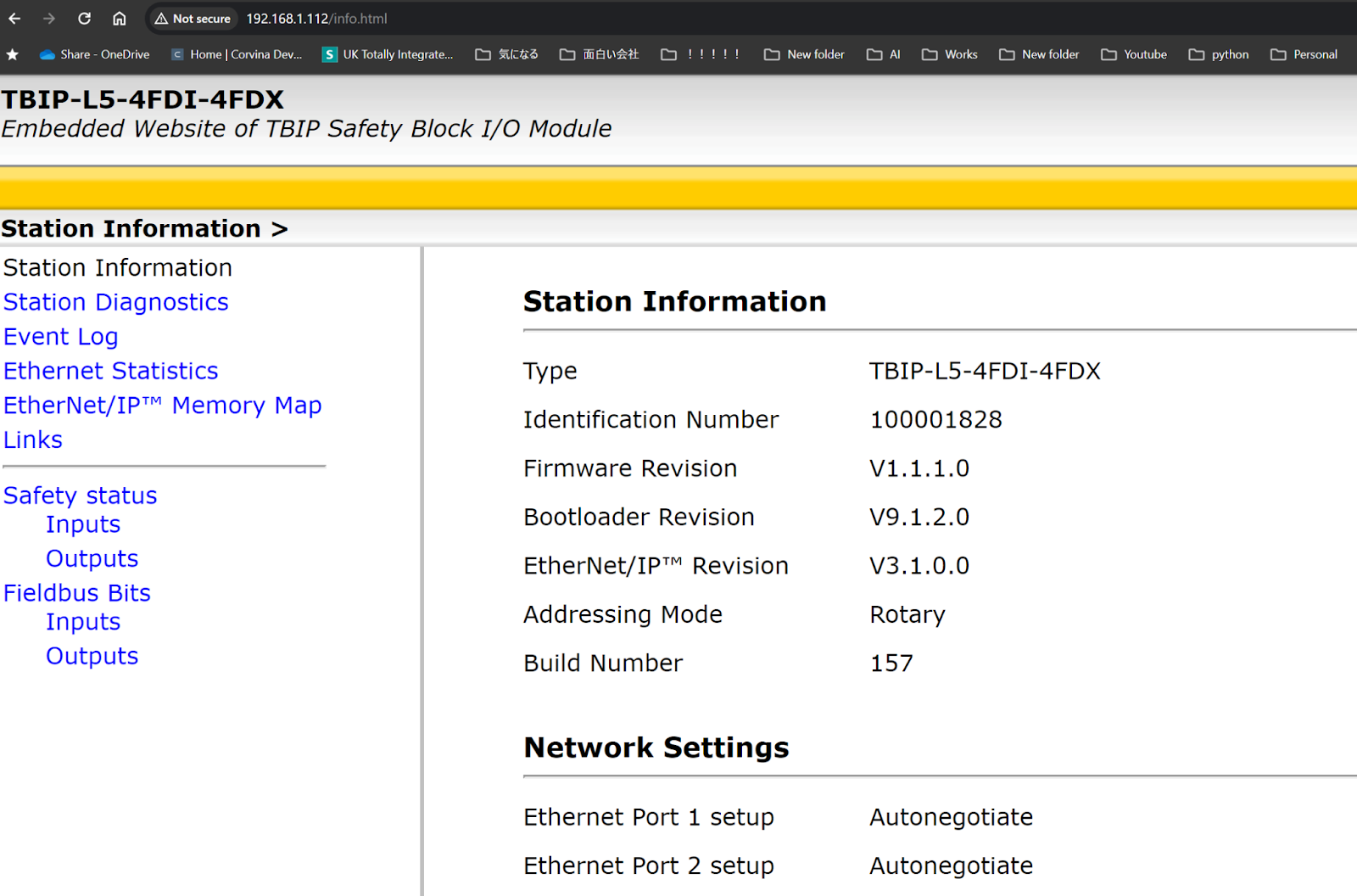
Access WebServer
Access the web server of the Turck CIP Safety module.
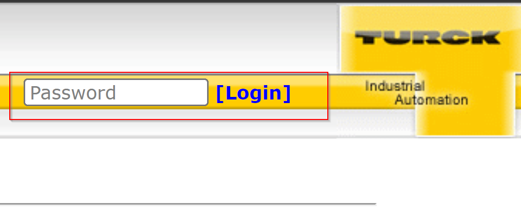
Login
Login using the Login button on the right.
Default Password is password.
Done!After login, there are more items that can be set.
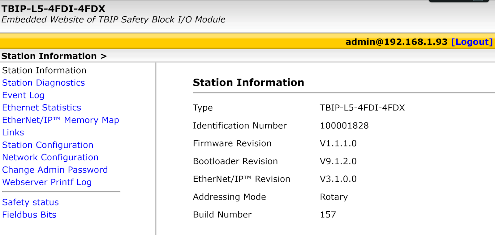
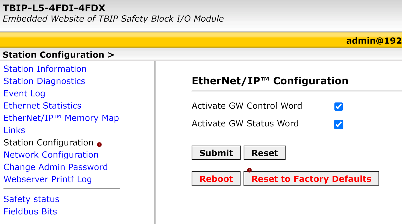
Factory Reset
Initially, Factory Reset the CIP Safety module.
Click Station Configuration>Reset to Factory Defaults.
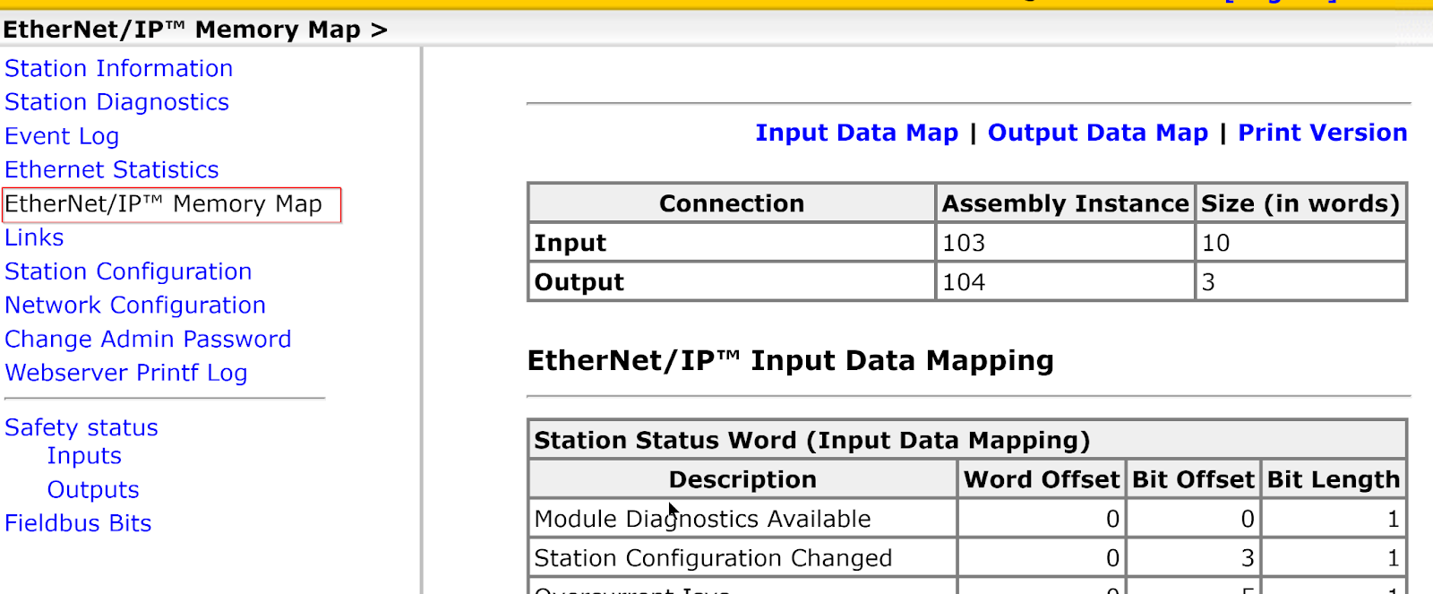
Etherent/IP Memory Map
This is the Instance number and memory Mapping used for the Normal Ethernet/IP connection of the Turck CIP Safety module.
Install the Tools
Now download Turck’s Safety Configurator from the following website.
Note that you will need a coupon code to download the software and you will need to contact your local Turck Office.
https://www.turck.jp/ja/product/SW_Turck_Safety_Configurator
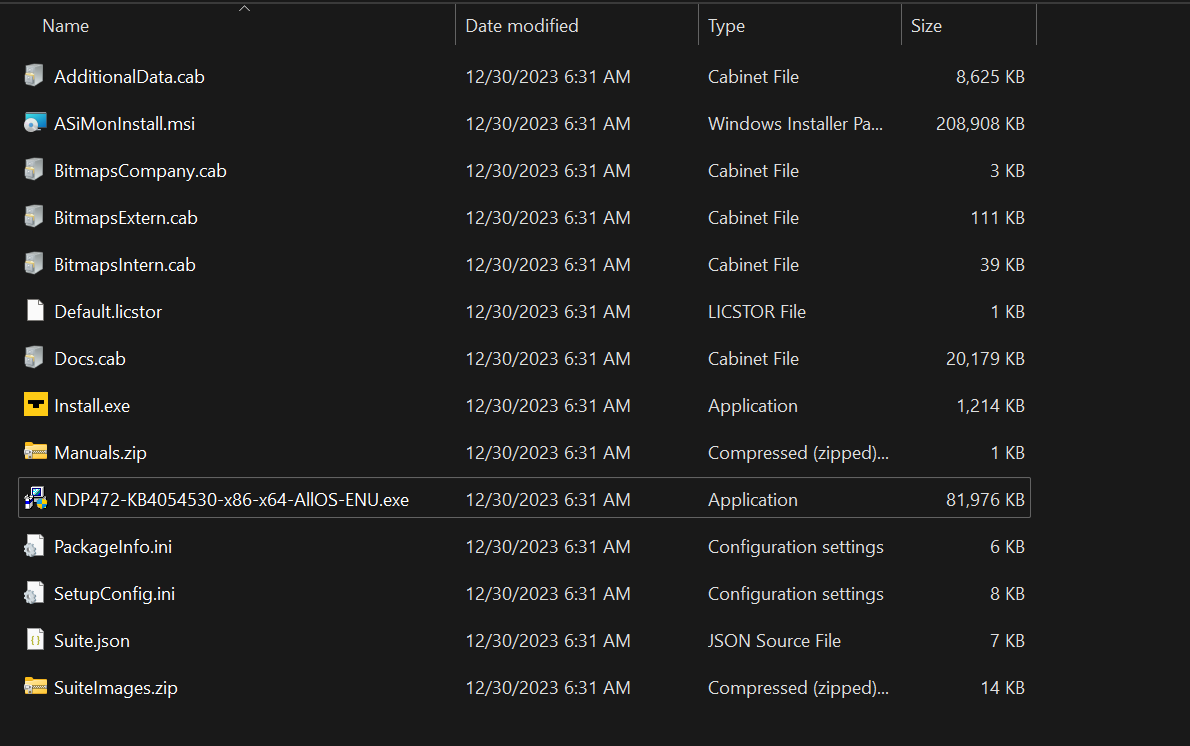
Double-click Install.exe to start the software installation.
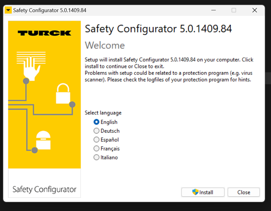
Select the language and proceed with Install.
Just a while..
Proceed with Next>.
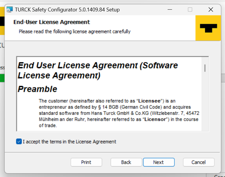
Agree to the licence and proceed with Next.
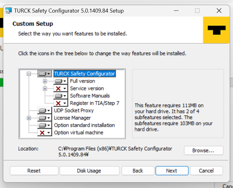
Proceed with Next.
Start installation.
Just a while..
Done!
Close the installer.
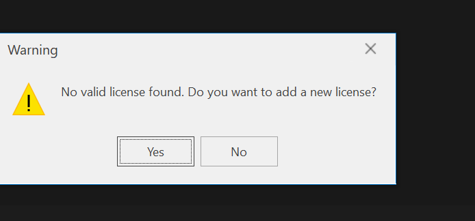
Next, you will be asked to enter the license and proceed with Yes.
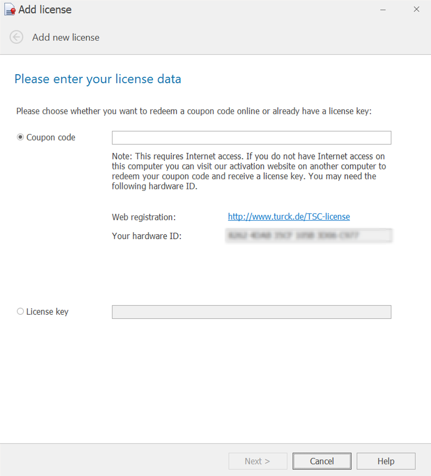
Select Coupon Code and enter the Coupon Code you used when you downloaded the software earlier.
Just a while..
Done!
Create your project
Start Turck’s Safety Configurator.
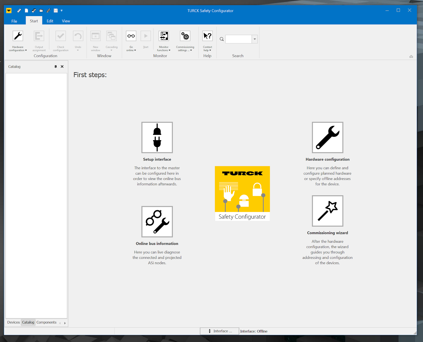
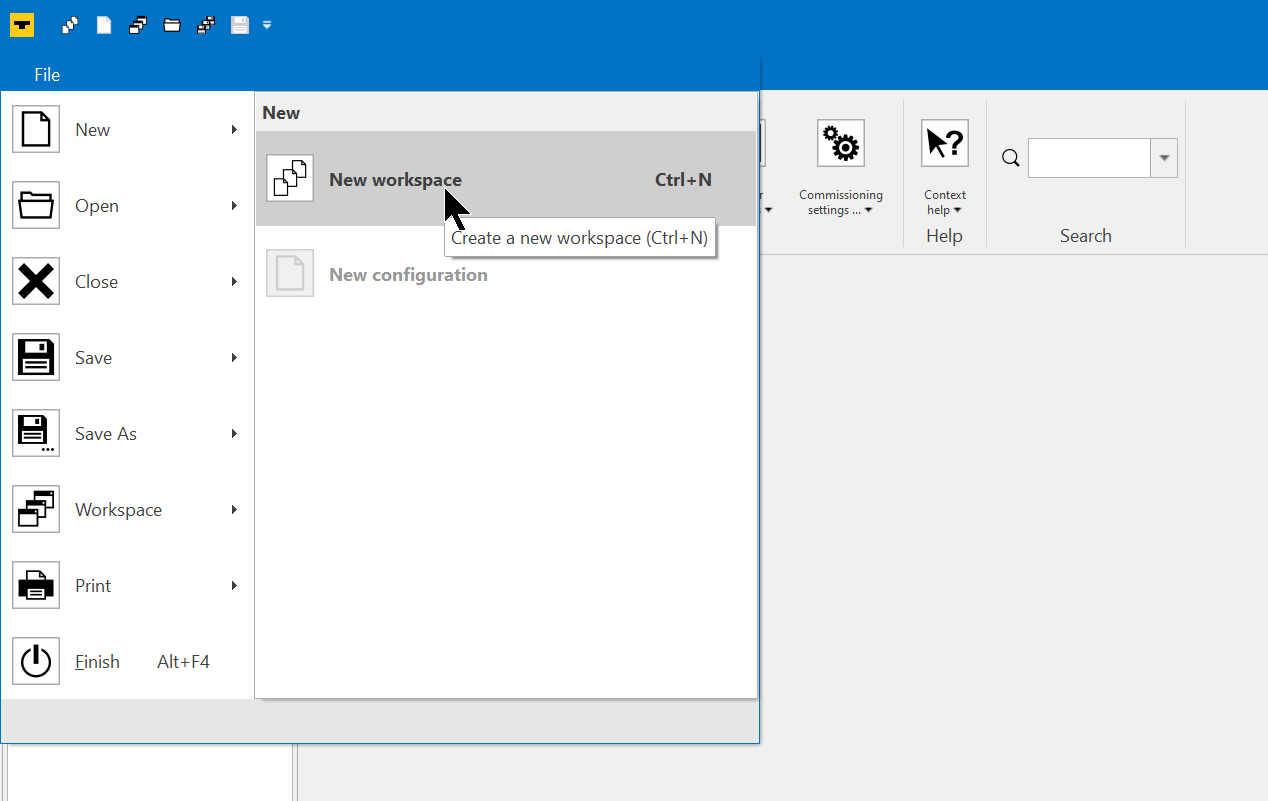
Create a new Workspace at File>New>New Workspace.
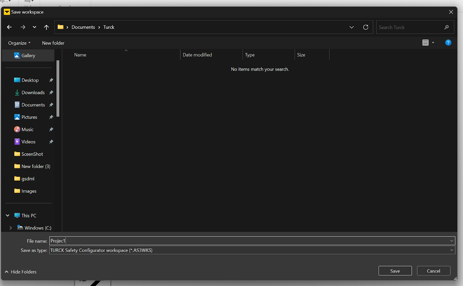
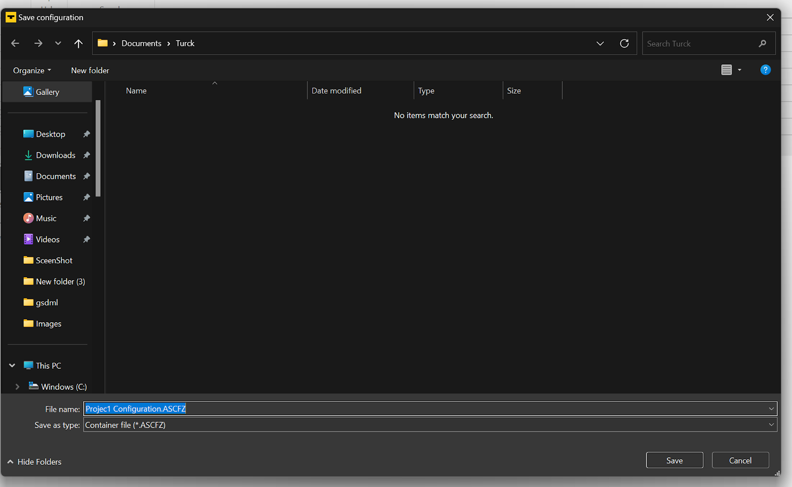
Set the Workspace storage location.
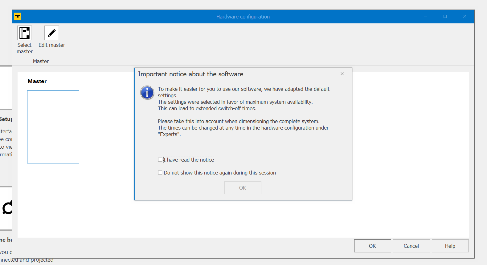
Check and proceed with OK.
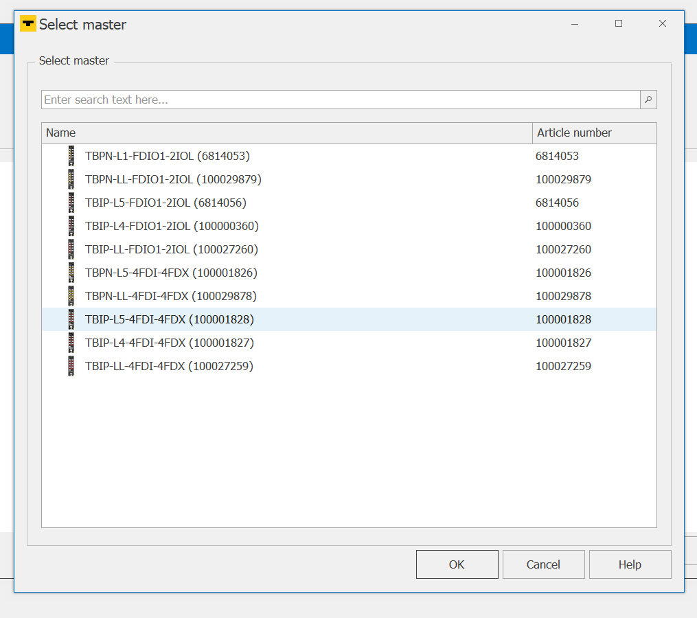
Select the Safety IO Block to be used in the project.
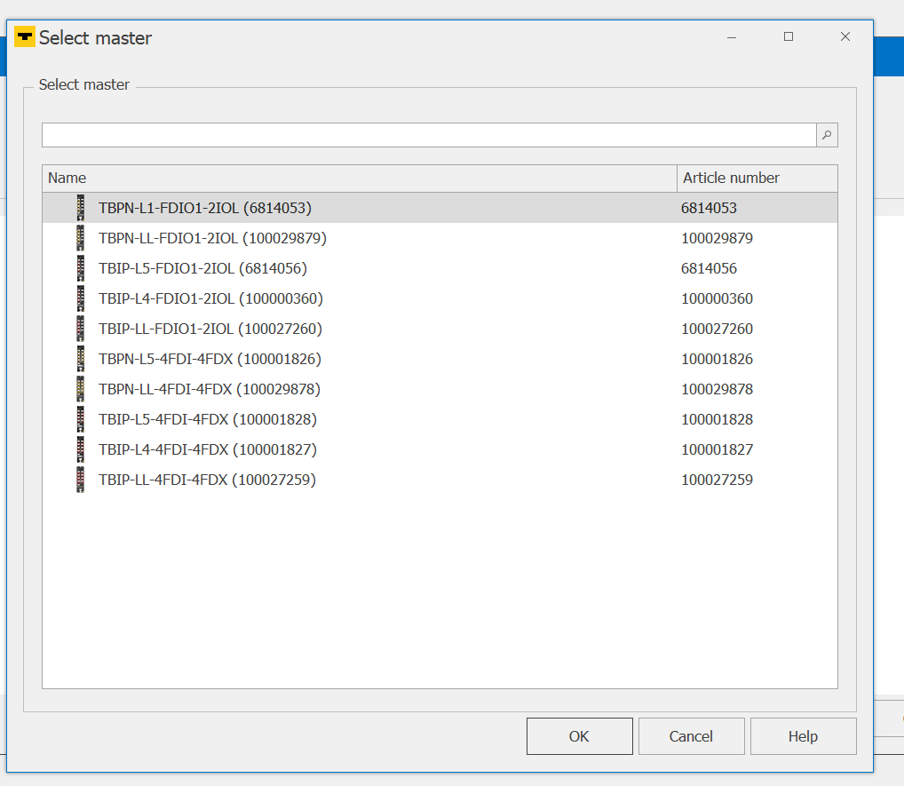
The device used in this case is the TBIP-L5-4FDI-4FDX, so you can either select it directly from the list just mentioned or you can follow the Order Number to select the device.
Choose TBIP-L5-4FDI-4FDX and proceed with Ok.
OK to confirm.
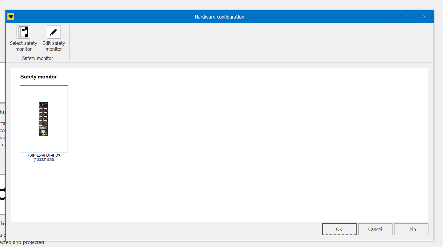
Next, the screen changes to the Safety IO basic settings screen.
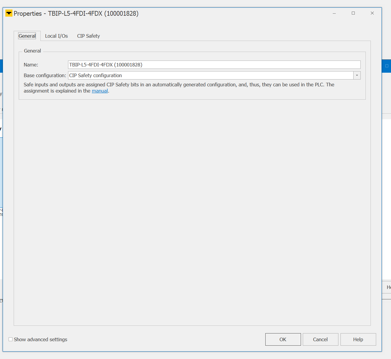
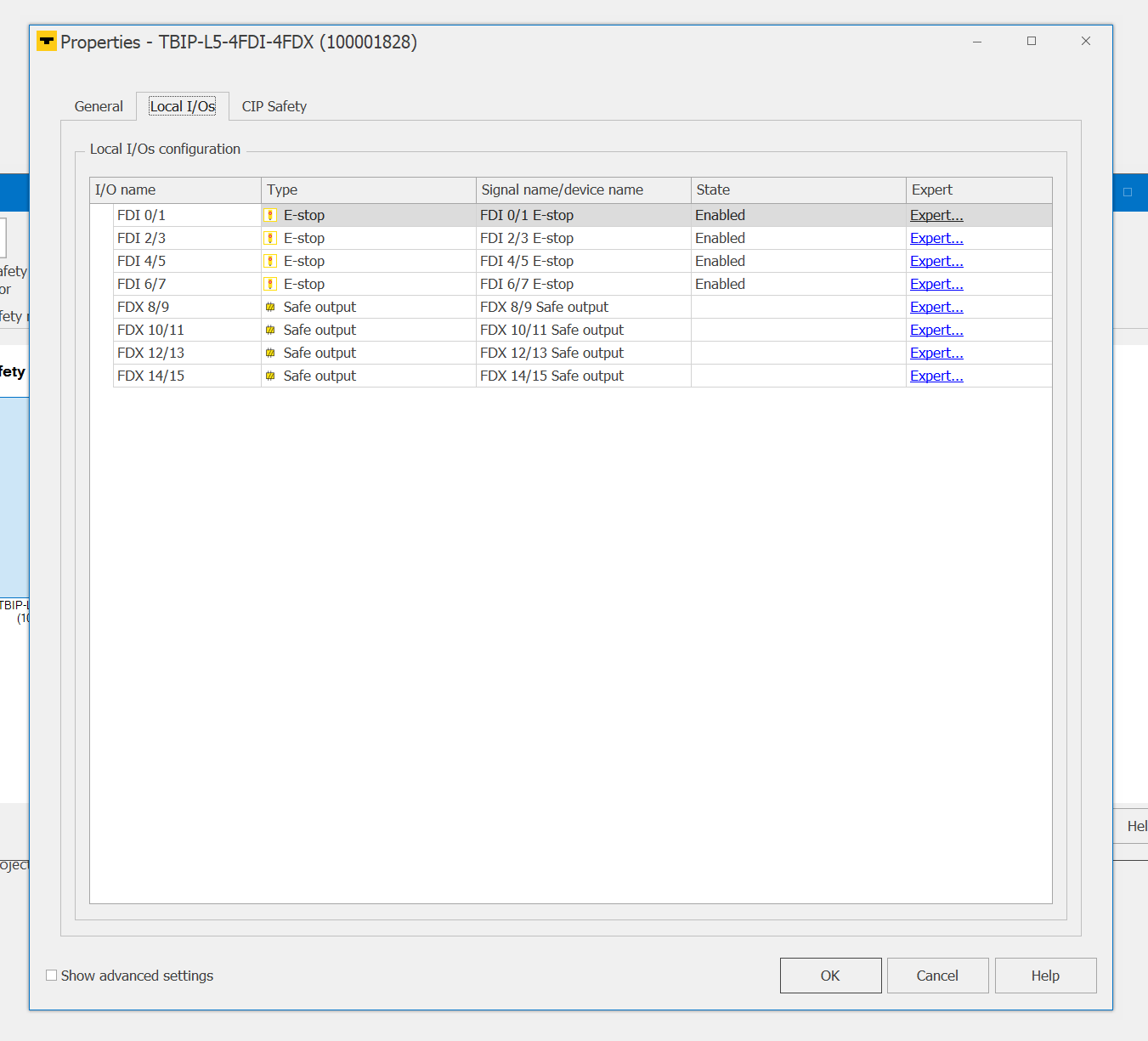
Local I/Os can be configured for each IO Port of the Safety IO Blocks.
In this article, all will remain Default.
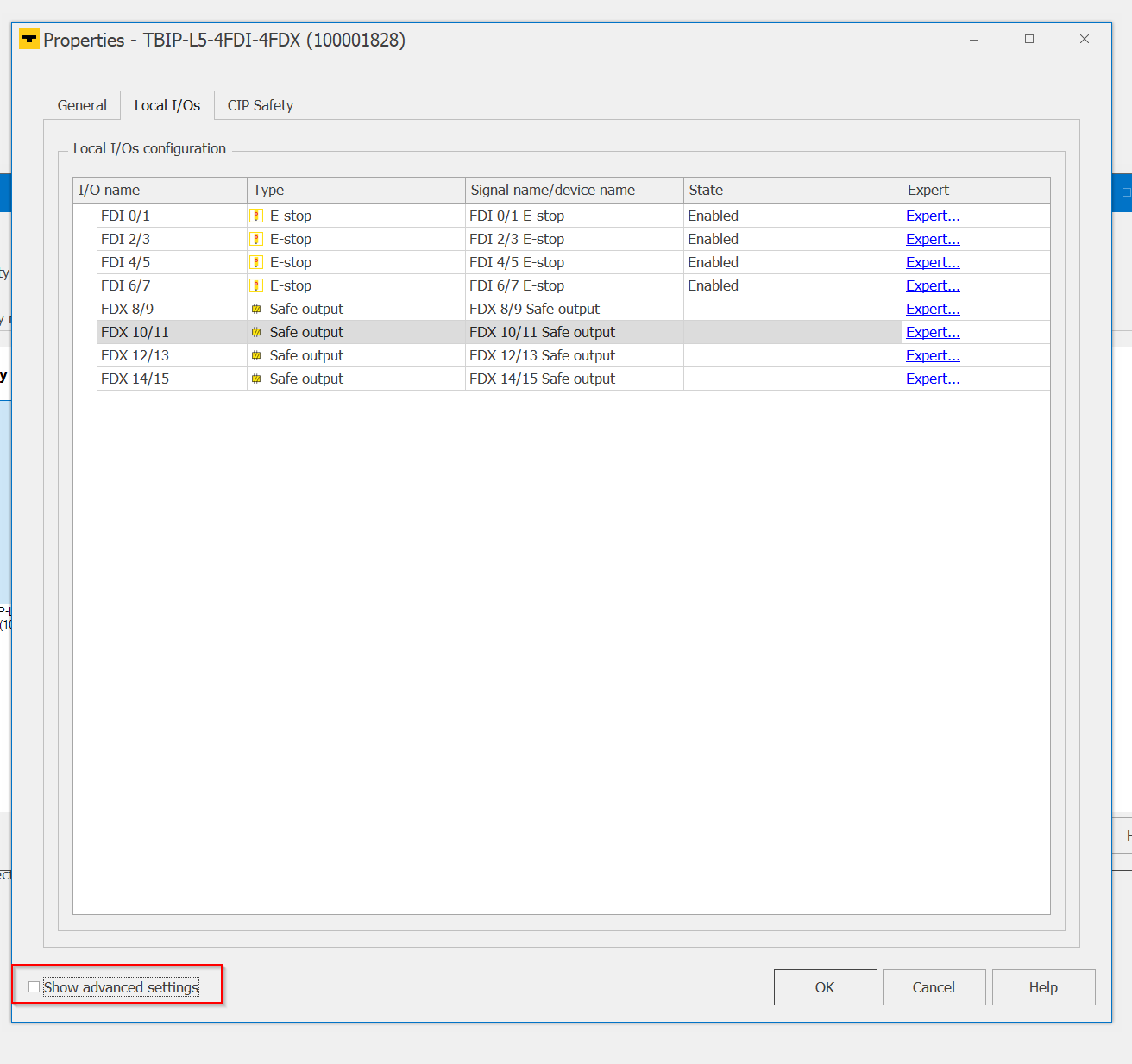
Now tick the Checkbox under “Show Advanced Settings”.
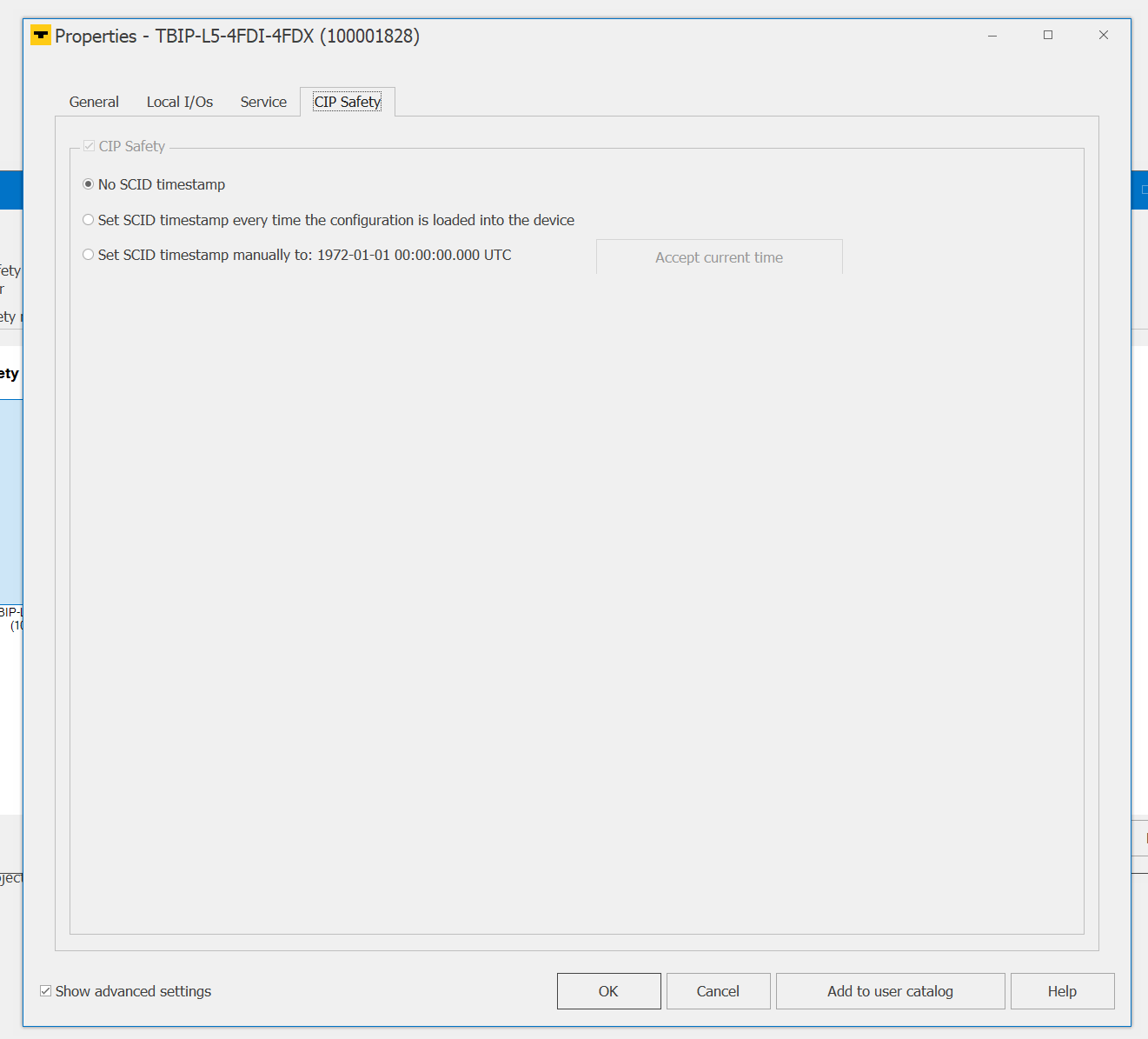
CIP Safety-related settings are also displayed on the Properties screen, such as SCID Time Stamp, but are not used in this article.
Proceed with Ok when all settings are complete.
Save the project.
Commissioning Wizard
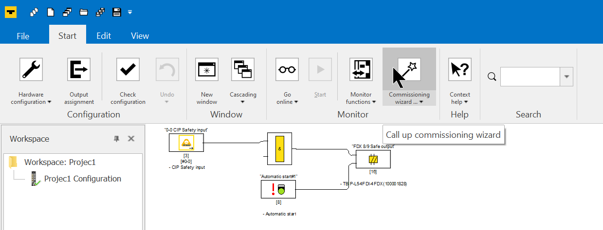
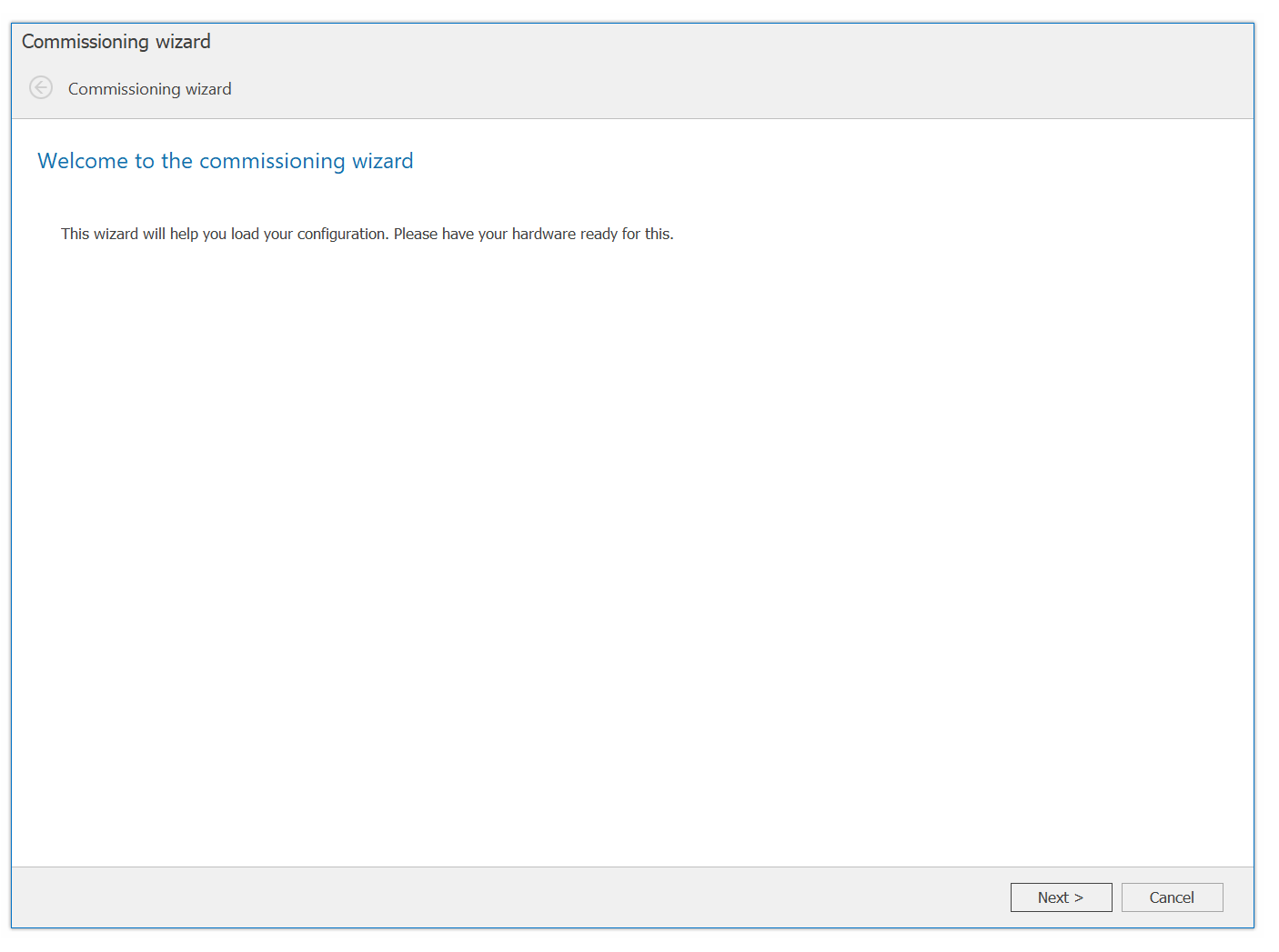
Now start the Commissioning Wizard to connect the device with the CIP Safety Configurator in Turck.
Proceed with Next>.
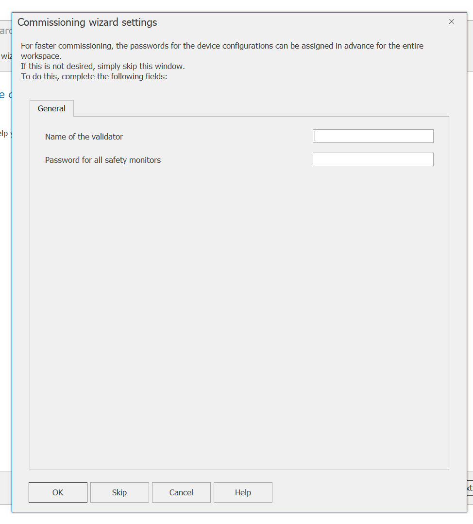
You can set the authentication User Name and Password for the Safety project.
Of course, that Step is not always necessary, so you can Skip it if you do not need it.
Note that if you set a User and Password, you will be asked for that Validator name and Password when downloading the Safety project.
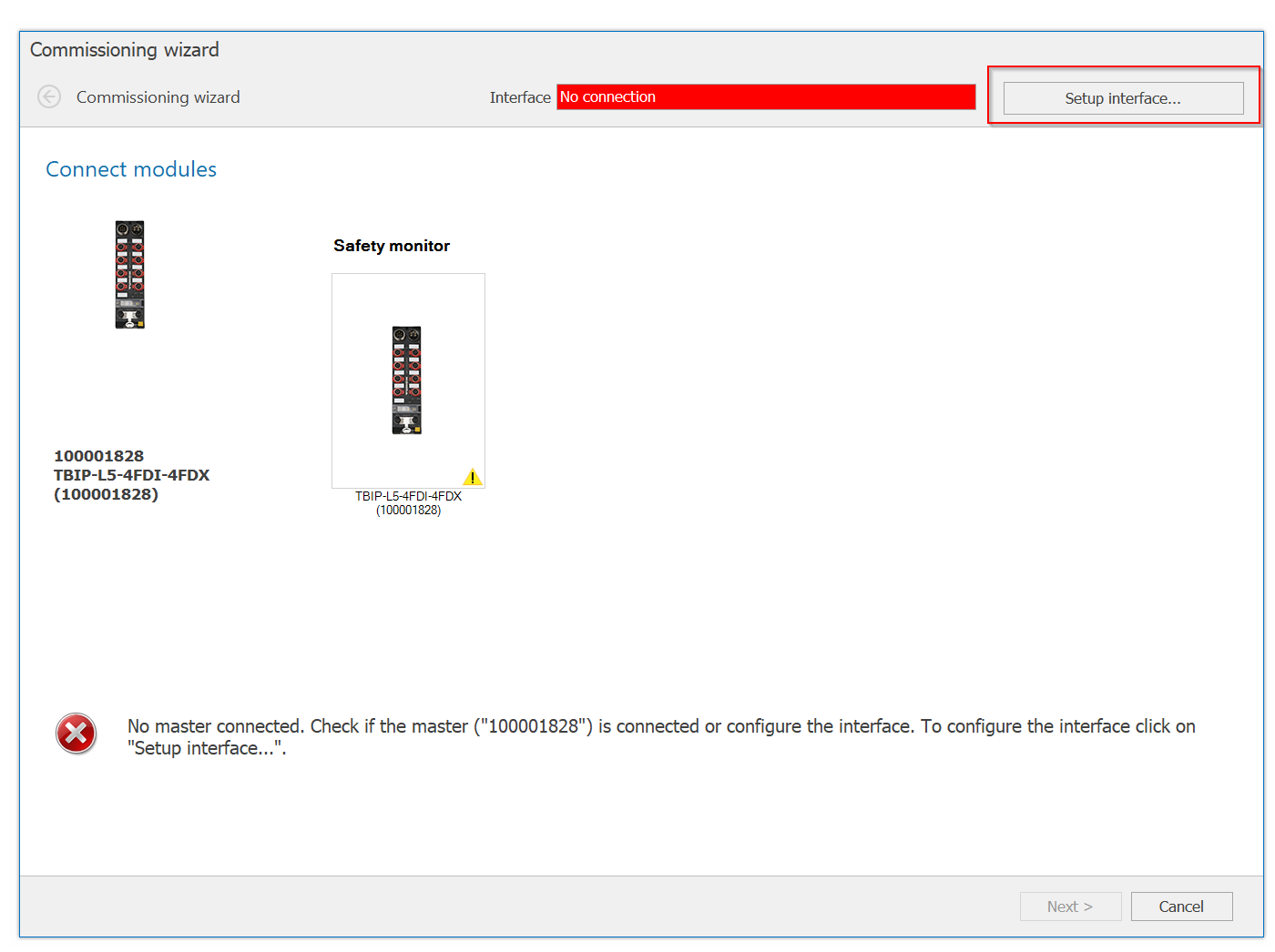
Initially, the error message “No Connection” is displayed. This is because the Ethernet Interface for the connection between the PC and the device has not yet been set up.
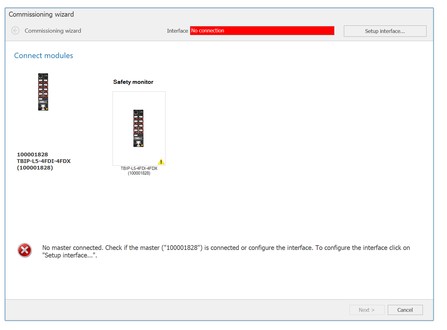
Click Setup Interface.
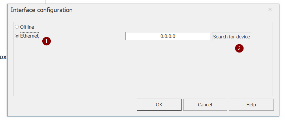
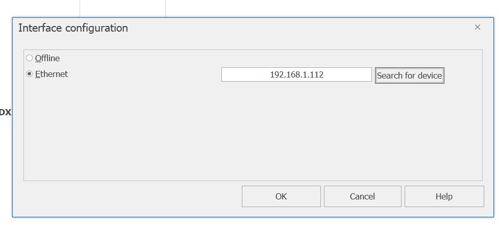
The Interface Configuration screen appears.
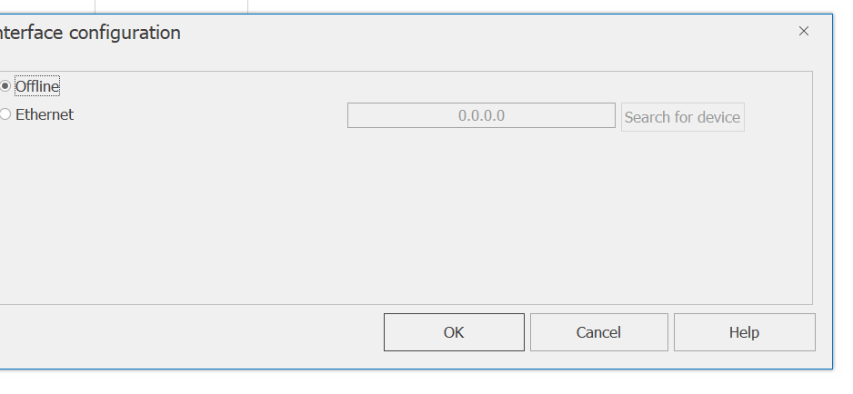
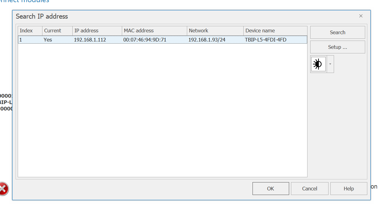
Select Ethernet and click >Search for device.
Done!You have found the CIP Safety IO Module from Turck. Select that Module and proceed with Ok。
Finally, click the Ok button to connect the PC and the device.
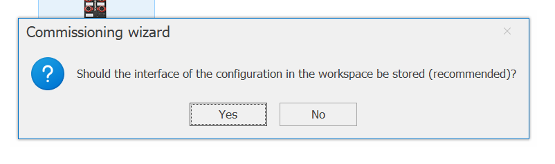
Yes to save the Configuration.
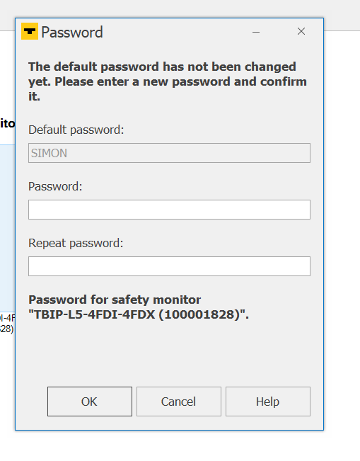
Change the Default Password and proceed with Ok.
Just a while..
Done!
OK to proceed.
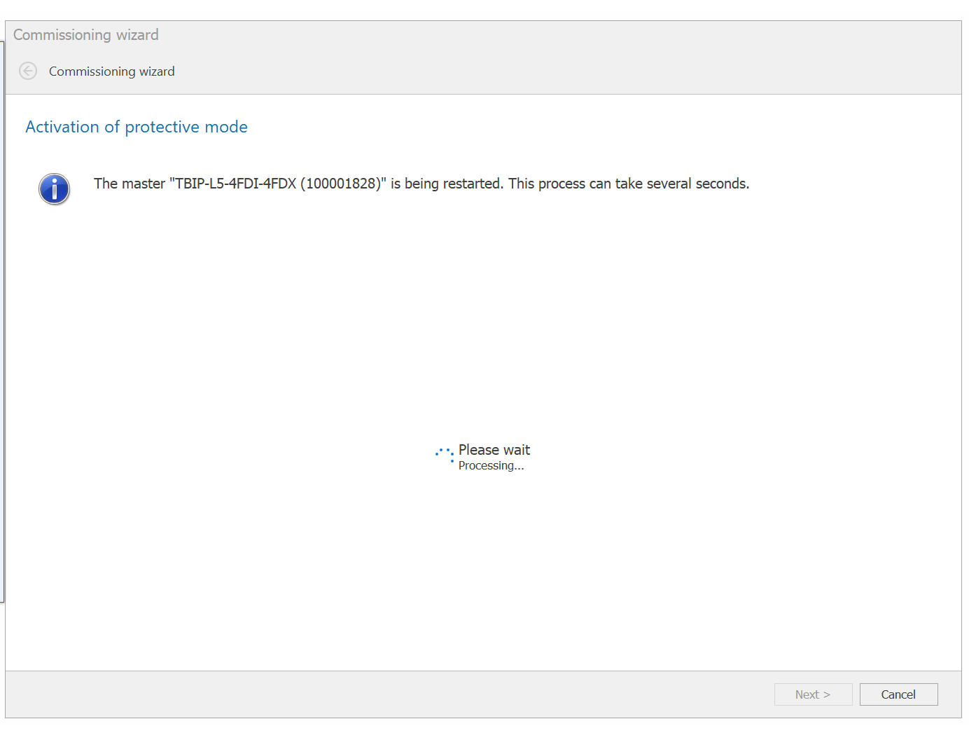
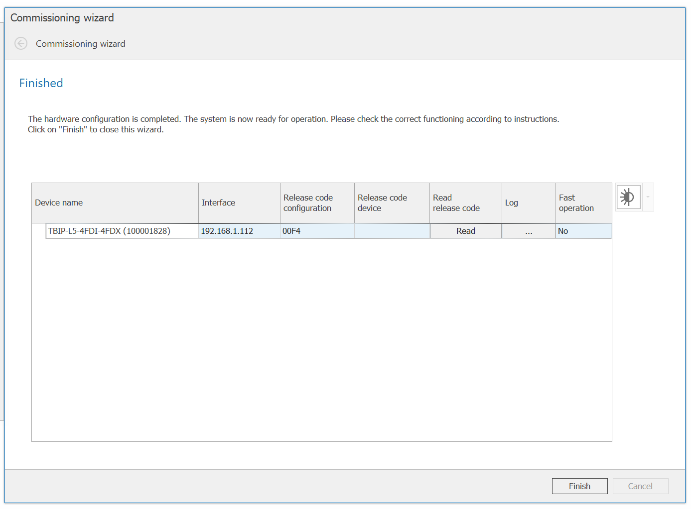
Please wait a moment while the Module restarts…
Click Finish.
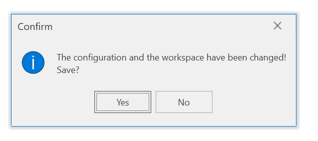
Finally, save the modified Configuration.
Assing Output
The Turck CIP Safety IO Block also has freely assignable output areas for CIP Safety and Normal Ethernet/IP, allowing various states to be fed back upwards depending on the application.
Assign output data via Start>Output Assignment.
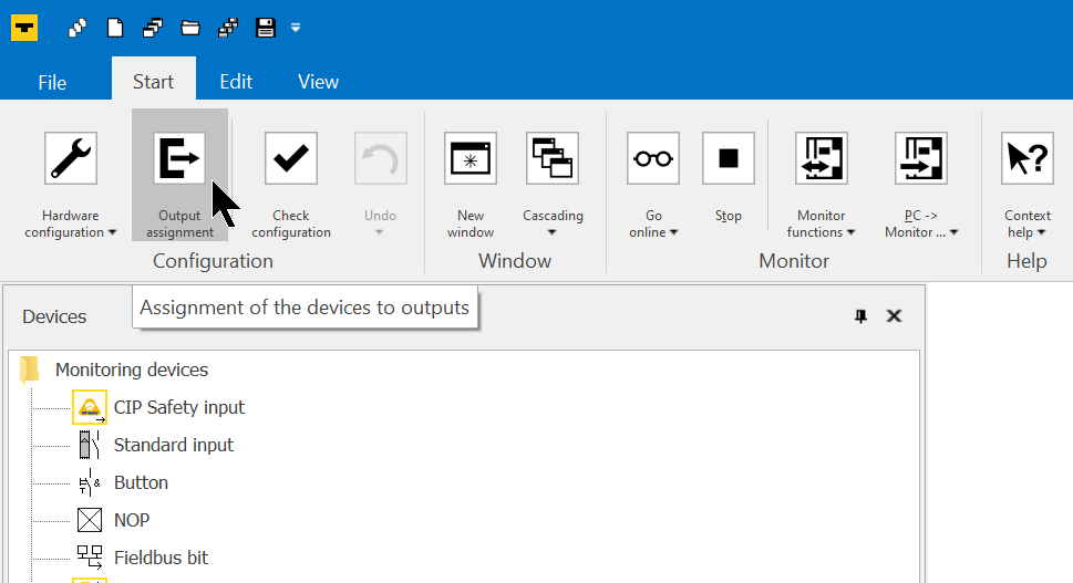
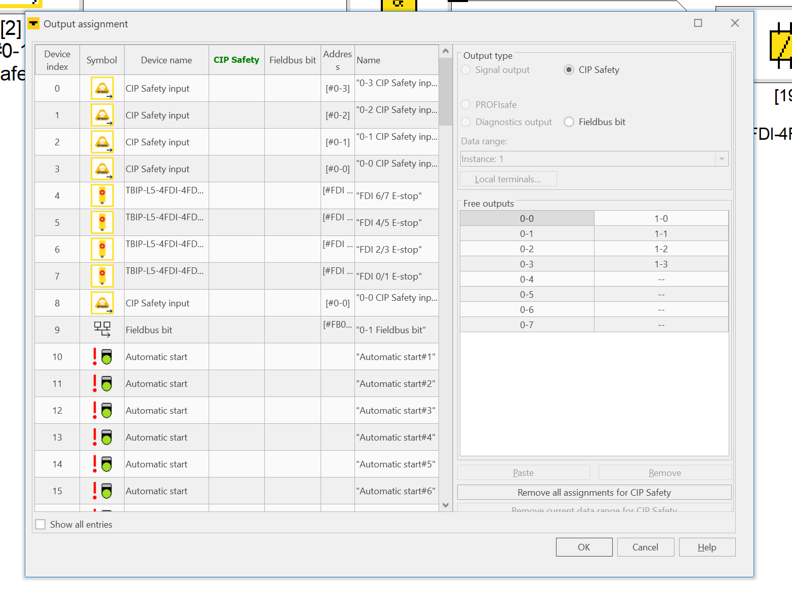
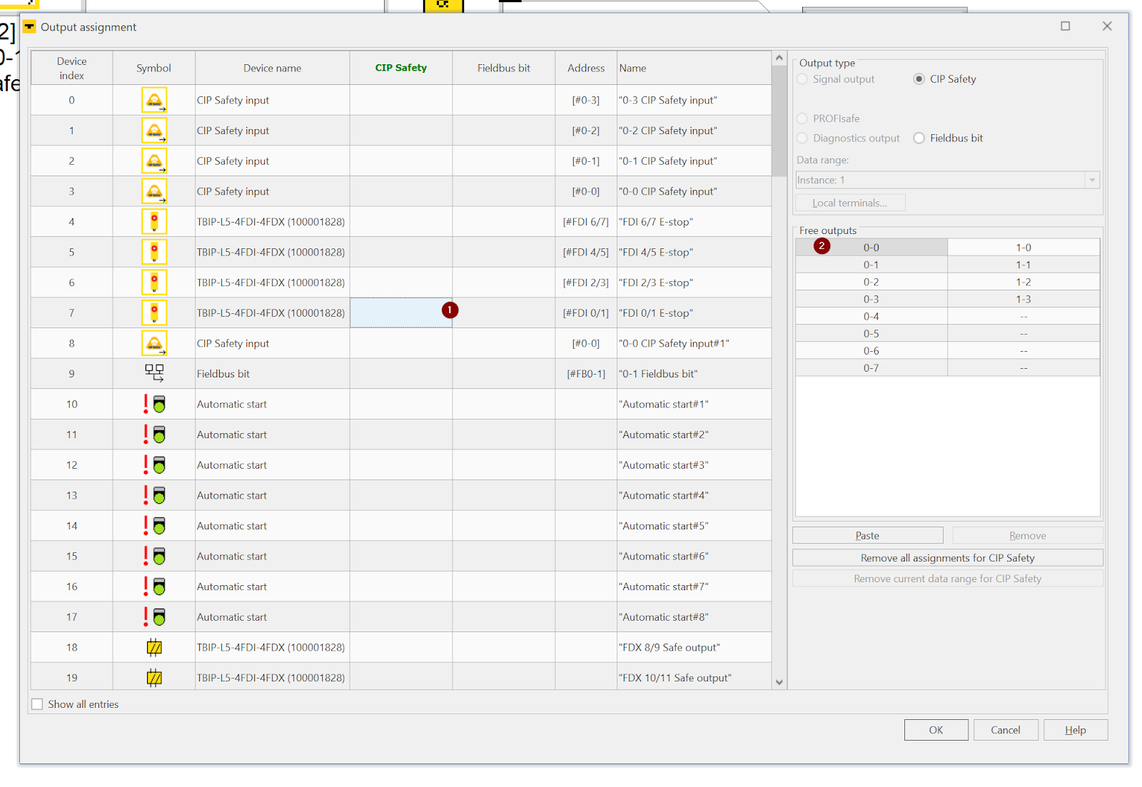
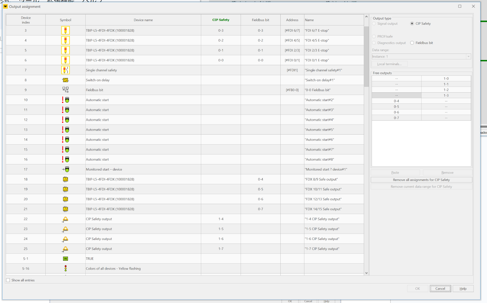
This is how the output allocation table is displayed.
CIP Safety
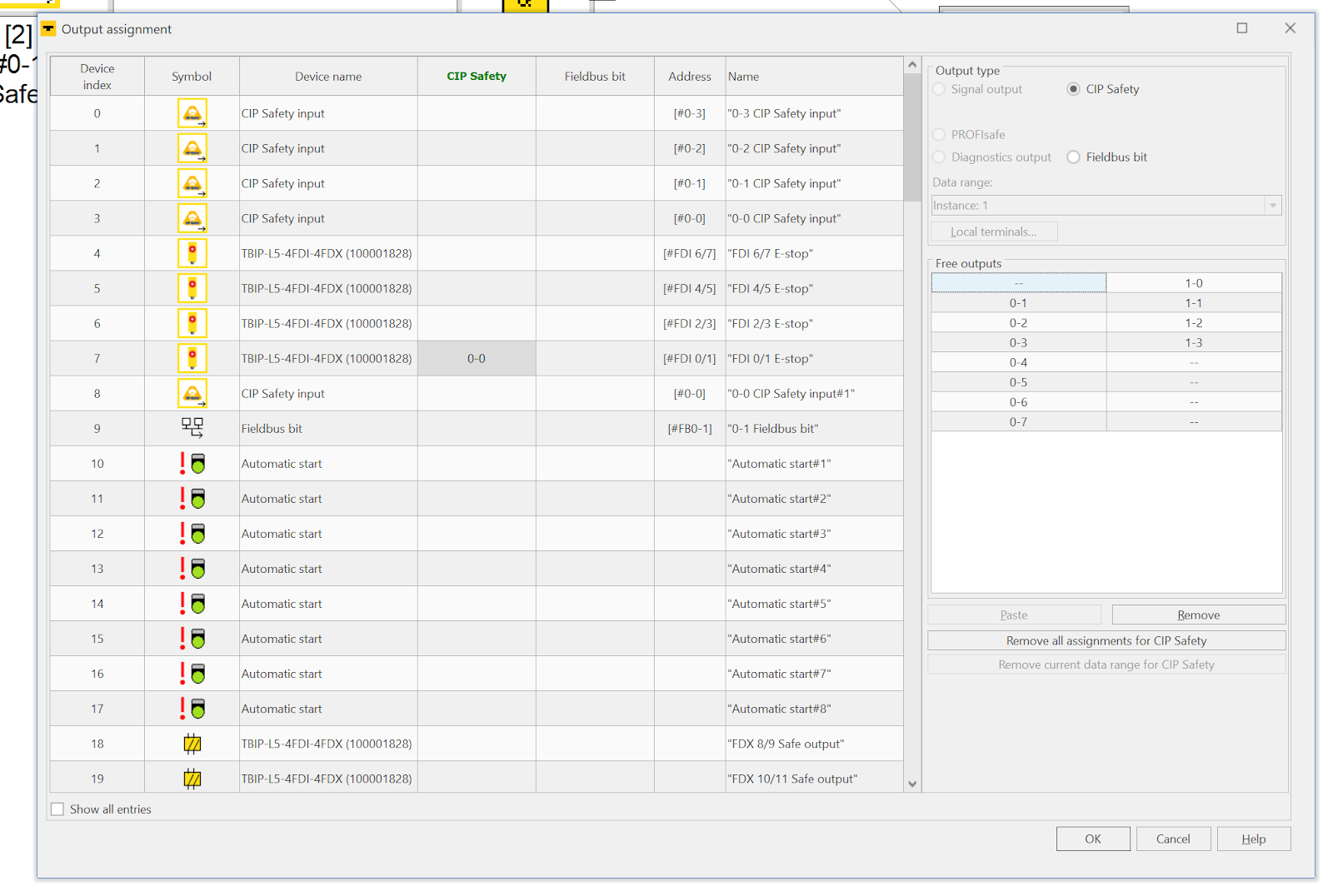
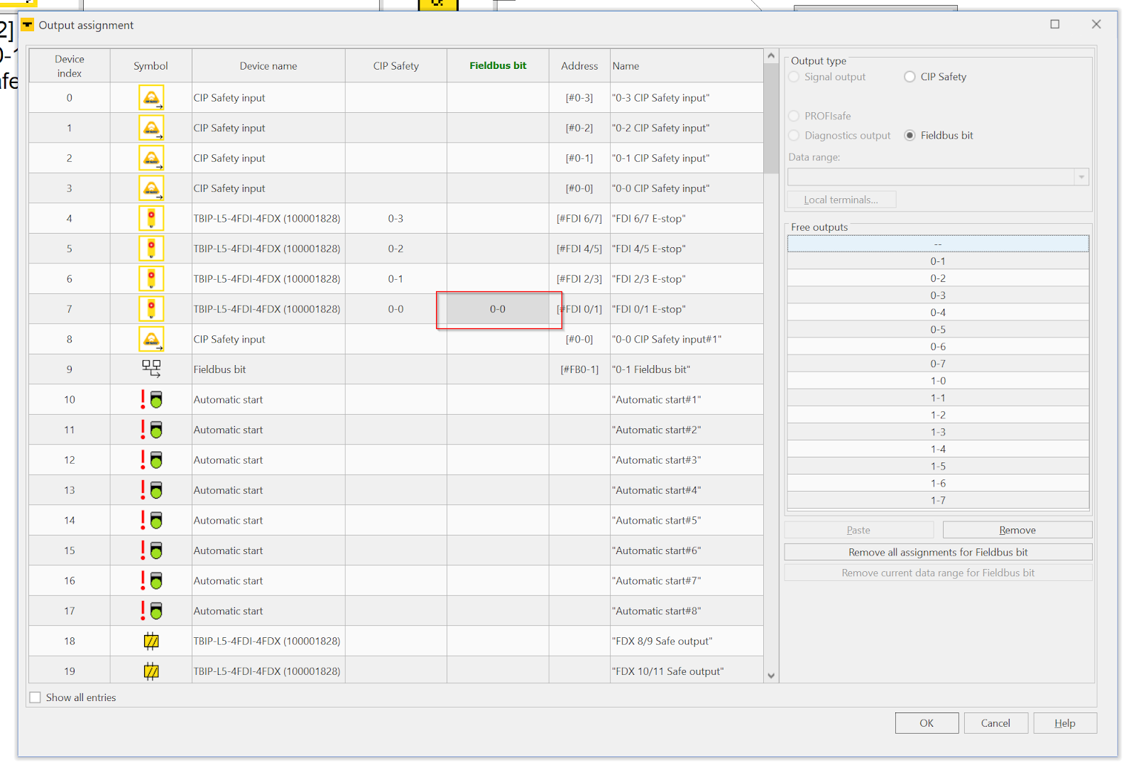
If you want to assign a device as an output for CIP Safety, select the CIP Safety field > and assign it to a Bit area that is not yet used in the Free Outputs section on the right.
You can map the device in Bit units, e.g. 0-0 for Bit 0 of Byte 0, 0-1 for Bit 1 of Byte 0 and so on.
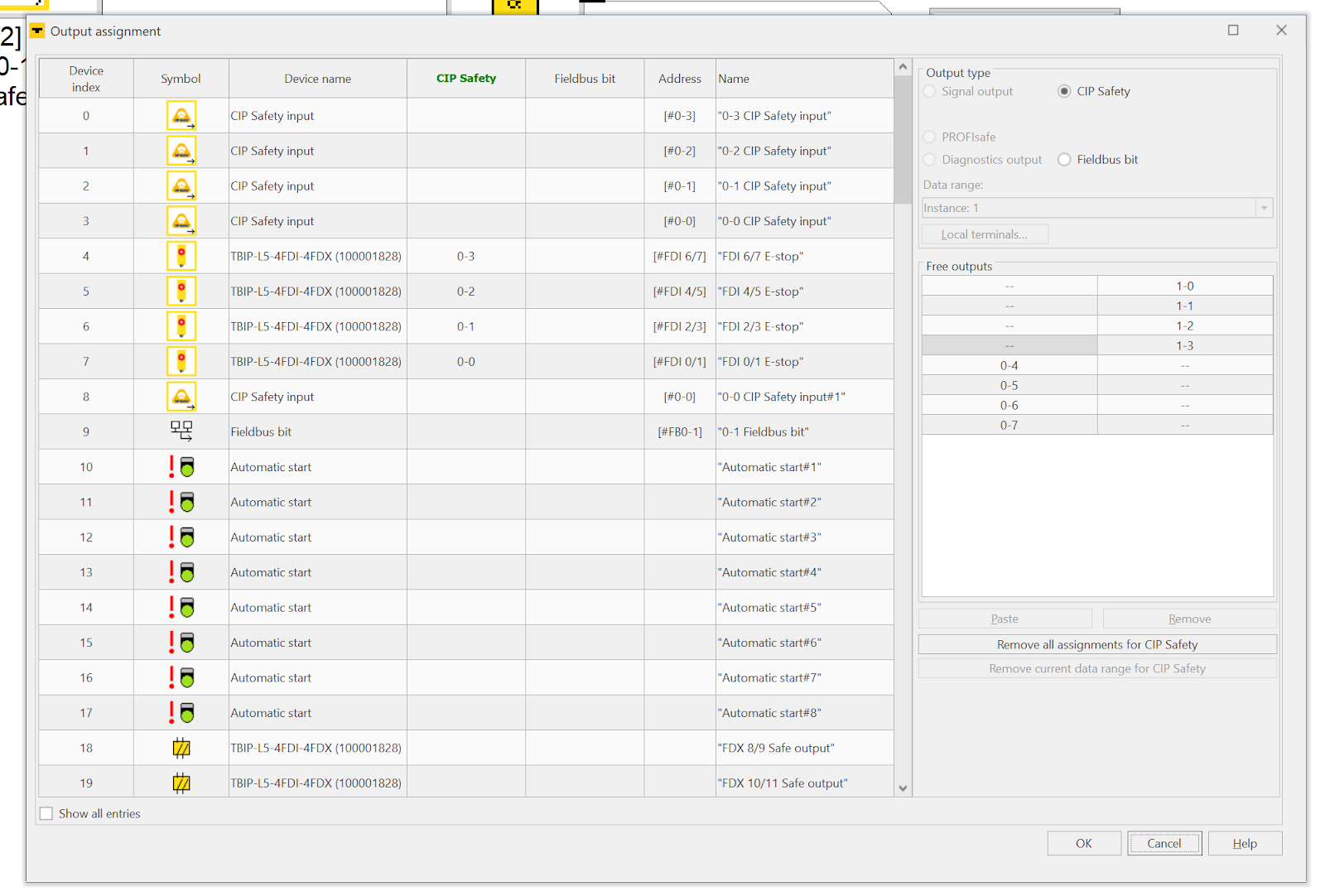
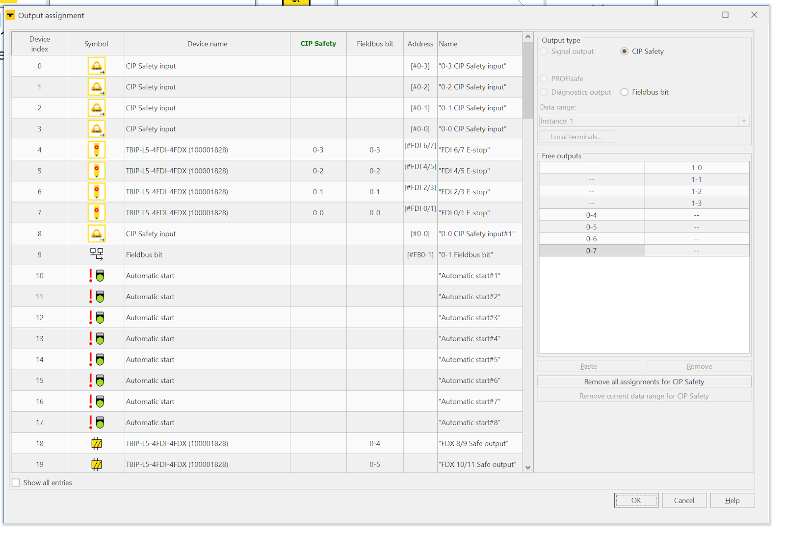
Done!This is OK.
The signal states of the four input Ports in the CIP Safety IO Block in Turck are now mapped to 0-0, 0-1, 0-2 and 0-3 of CIP Safety.
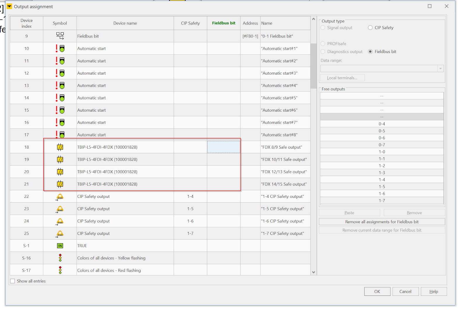
Fieldbus Bit
Now we need to assign the Fieldbus Bit. This area is used for the Turck Normal Ethernet/IP Instance 104 output. In the example below, the FDI 0/1 signal is selected as “Fieldbus” and a free area (Word Offset 0, Bit 0) is set in the Free outputs field.
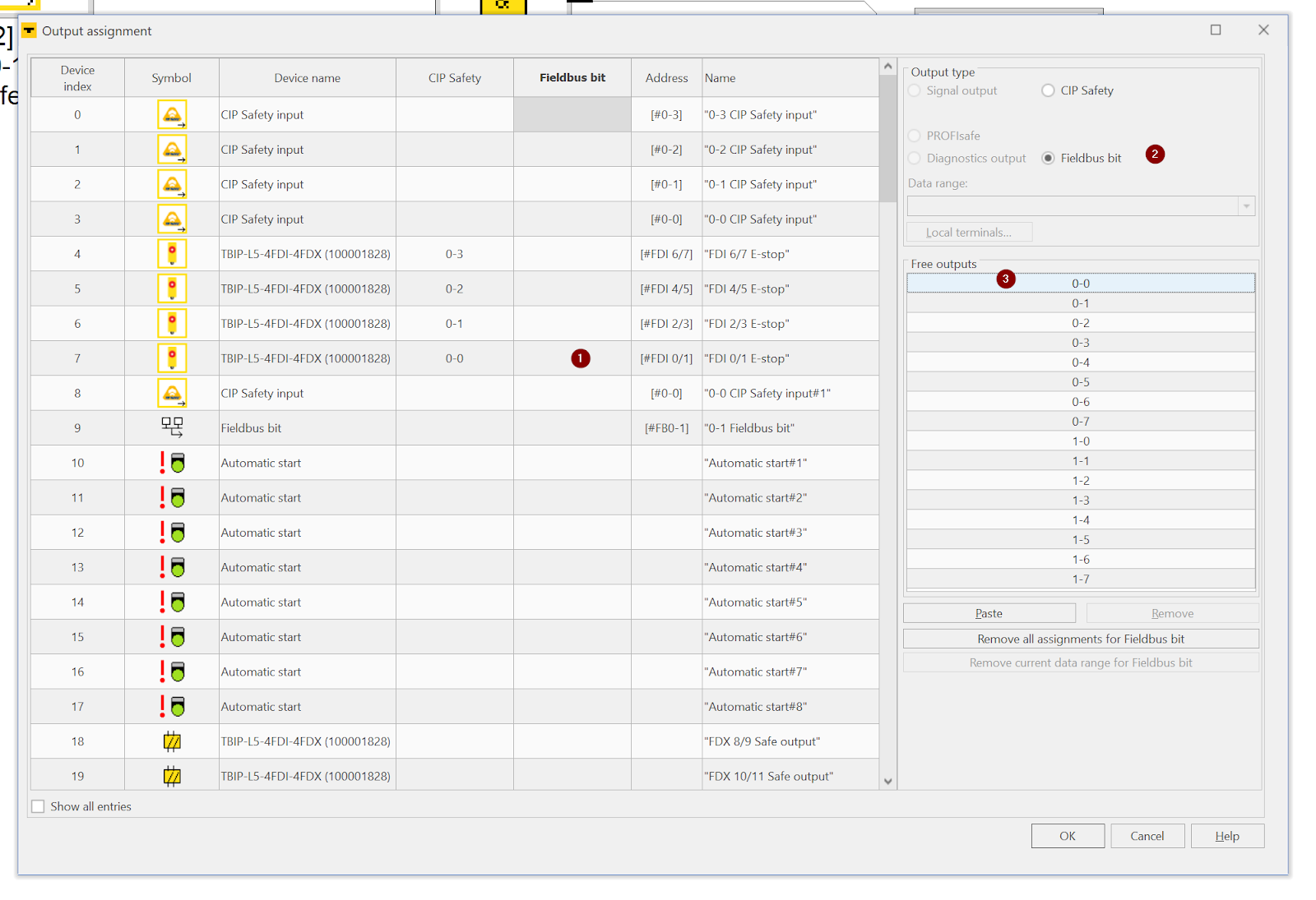
Done!
Allocated to Word Offset0,Bit0-3 as shown below.
Next, FDX outputs should be assigned to Fieldbus Bits in the same way.
Done!
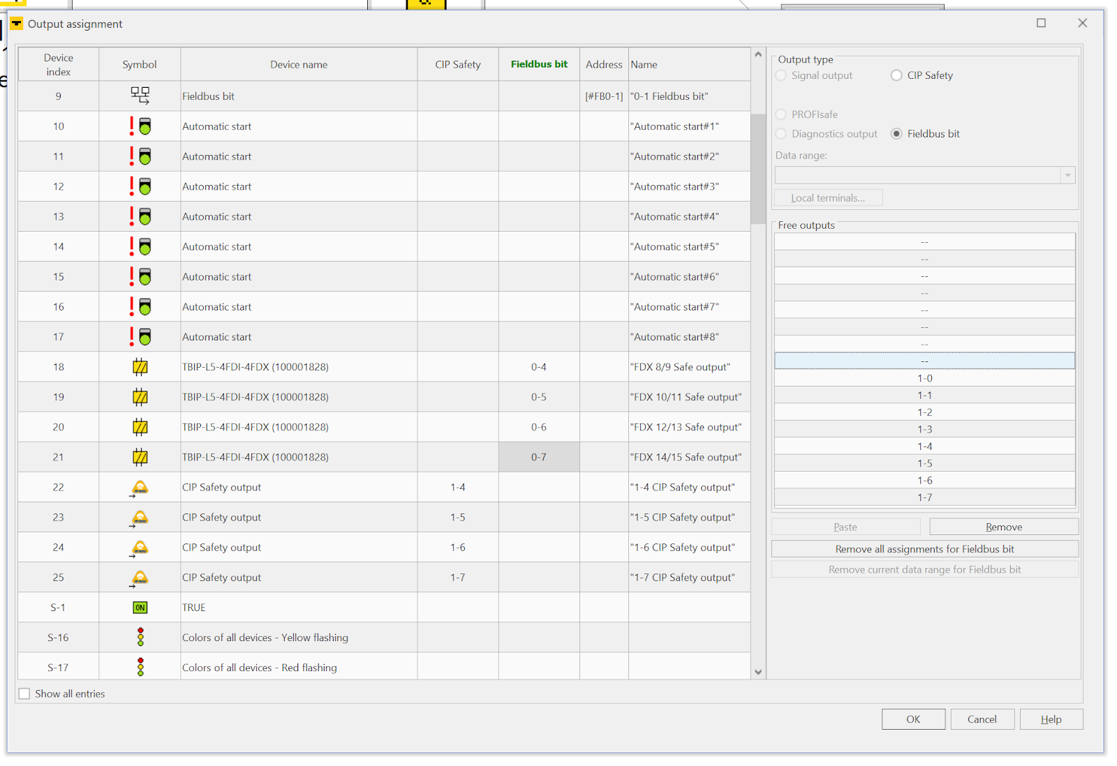
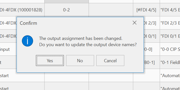
Finally, update Output devices.
Finally
This is the CIP Safety and Fieldbus Bit Mapping used in this article.
Safety Program
Turck’s TBIP-L5-4FDI-4FDX can not only be used as a Block IO, but can also create logic internally. By using internal logic, small applications can configure the system with several TBIP-L5-4FDI-4FDXs without the CIP Safety Scanner. Decentralized control also means that the CIP Safety Scanner has less logic, making it easier to switch to a third-party CIP Safety Scanner in the future.
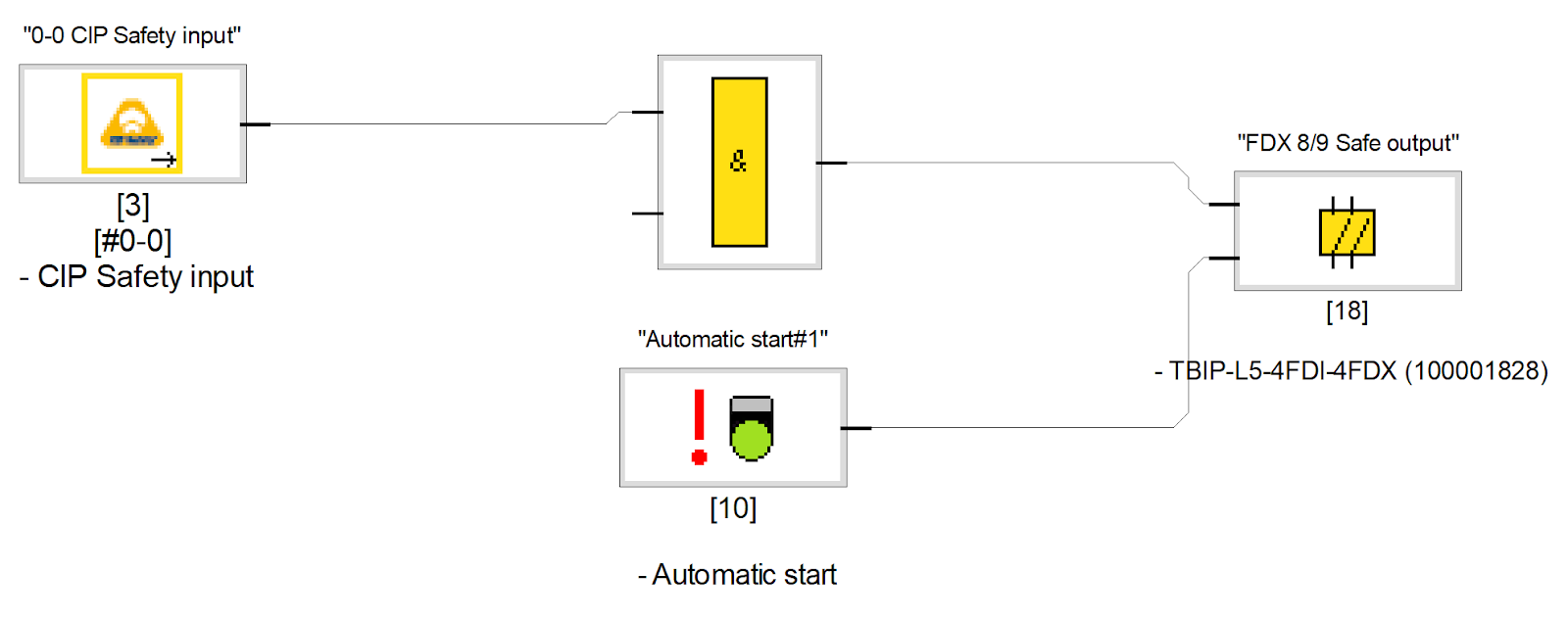
On Default, the state of CIP Safety input Bit 0 is connected directly to the CIP Safety output (automatic reset).
The Turck Safety Configurator can also be used to build applications without programming knowledge, as programming is completed by simply connecting Drop, Drag and Wire.
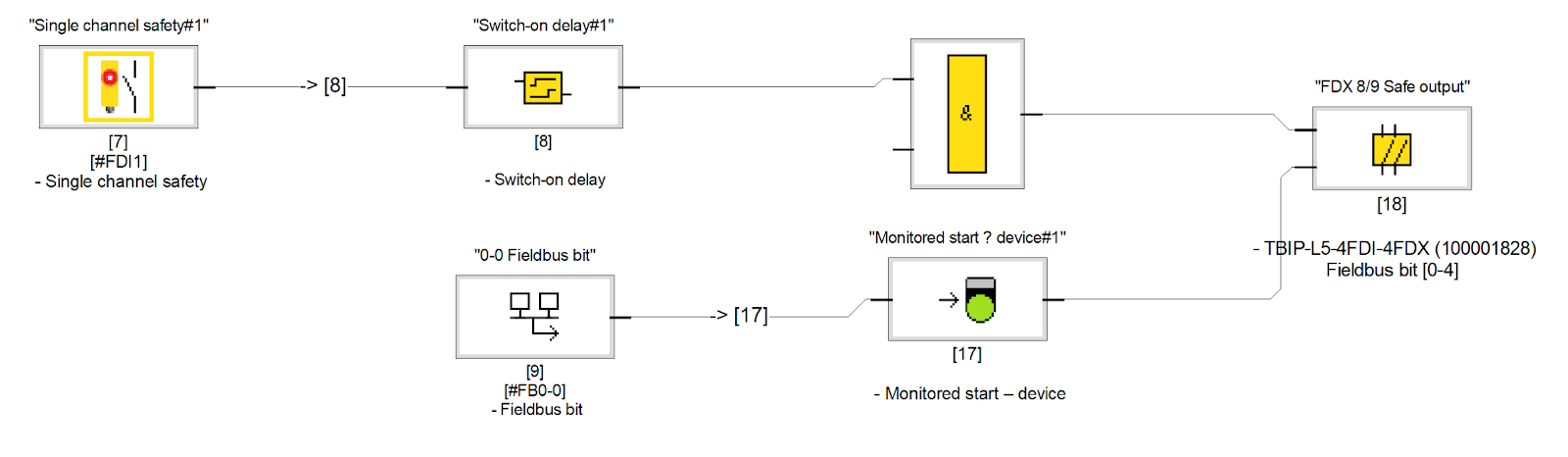
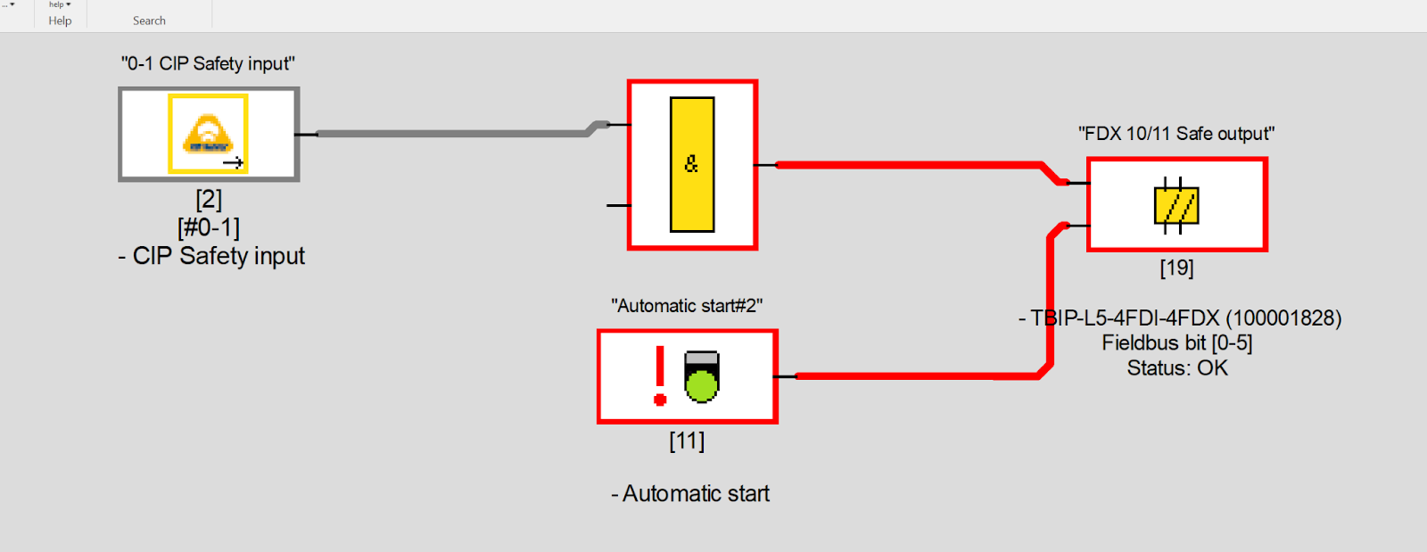
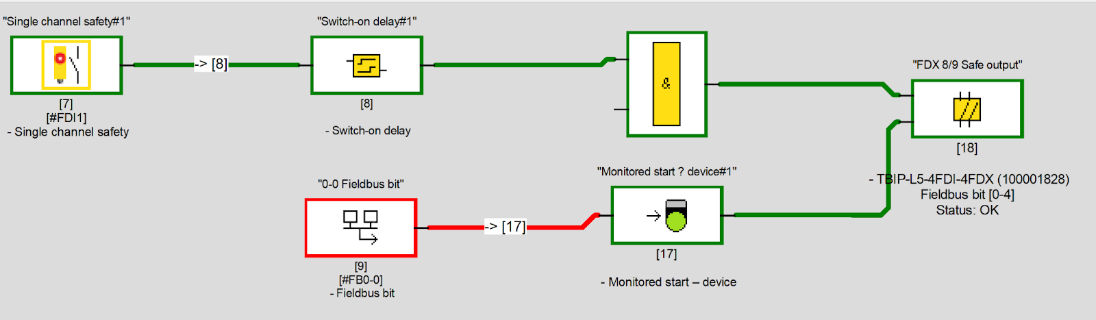
In this case, local logic is created on TBIP-L5-4FDI-4FDX. The programme Flow causes FDI 0/1 to be True>Wait for Delay of 2 seconds>Finally True the output FDX 8/9 by a False>True>False signal change of the Omron Fieldbus Reset signal.
Add Single Channel Safety
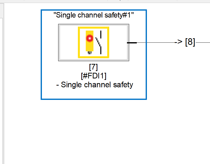
Drop Single Channel Safety because you want to Monitor the signal FDI 0/1.
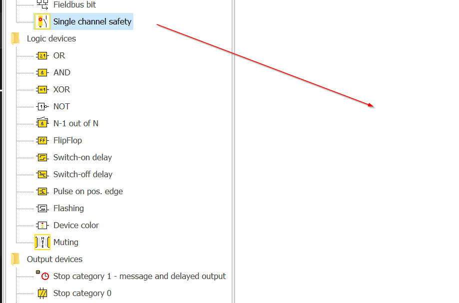
Done!Single channel safety#1 has been added.
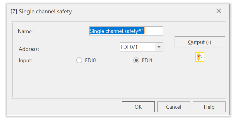
Name is the display name of the relevant Block on the Safety Configurator, Address specifies the safety input address where the module is to be used and Input allows the user to set which input is to be used.
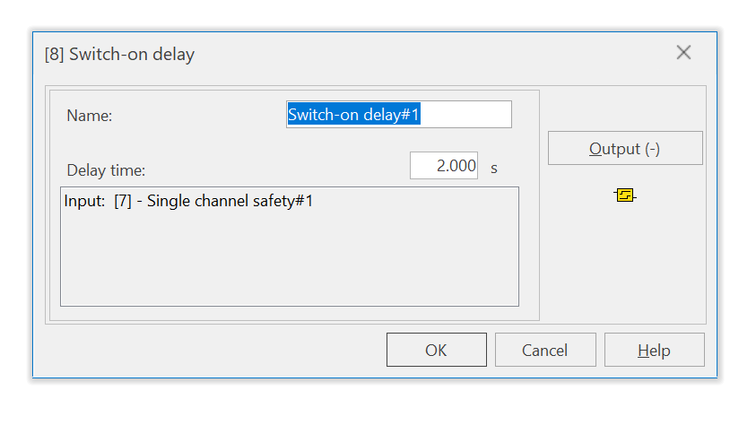
Add Switch-on delay
Drop Logic Devices>Switch-on delay into the project, this time to add a Delay-On Timer.
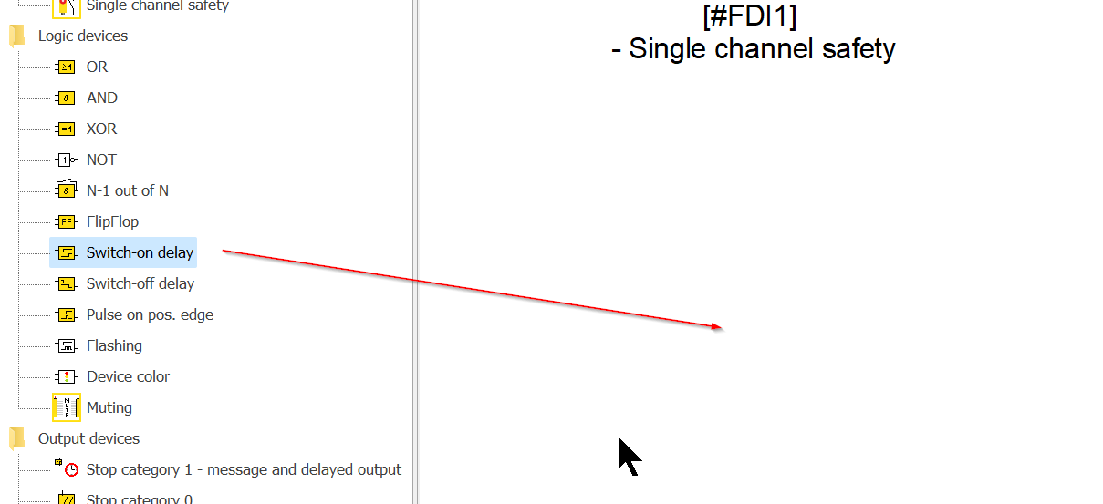
Done!
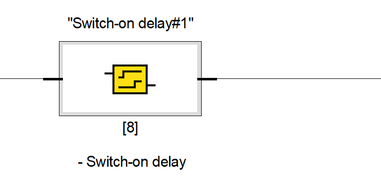
Name is the name of the On-Delay and Delay Time can be set as a constant.
Add Monitoring Devices
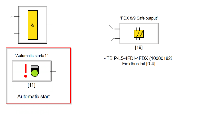
Next, we’ll build the unlock signal for the safety outputs, as everything in the Default project is automatically reset, so we’re not looking at the standing down signal we mentioned earlier.
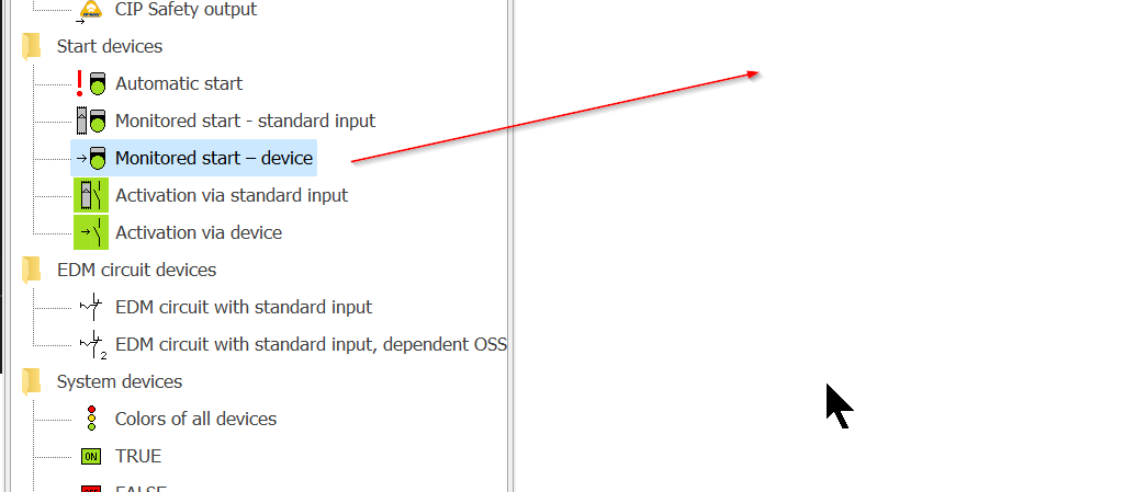
So let’s delete the Automatic start component in Default once and for all.
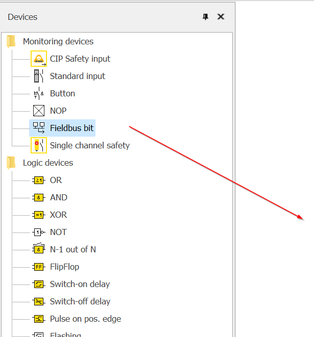
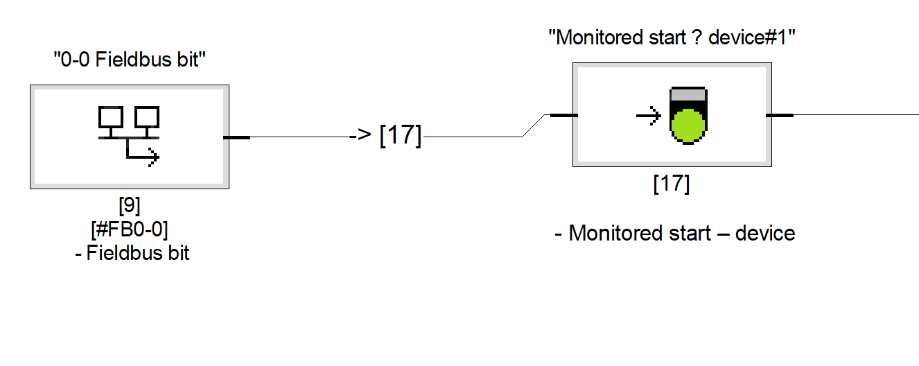
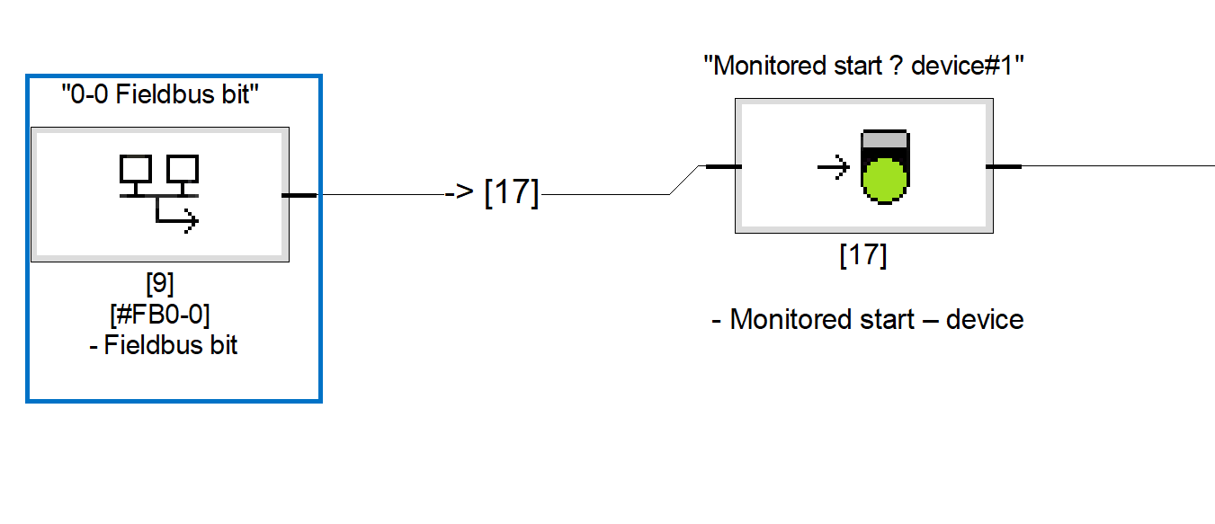
Next, add Start Devices>Monitored start-device to your project.
Add Fieldbus Bit
Now add the Fieldbus bit to be unlocked.
Done!
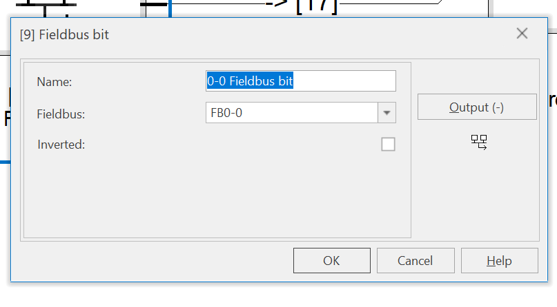
Next, double-click on the Fieldbus component you have just added to specify the Fieldbus Bit number to unlock via Ethernet/IP Connection.
It is currently set to FB0-0, meaning it corresponds to Fieldbus Word 0 and Bit Offset 0.
Finally
Finally, connect the components as shown in the diagram below.
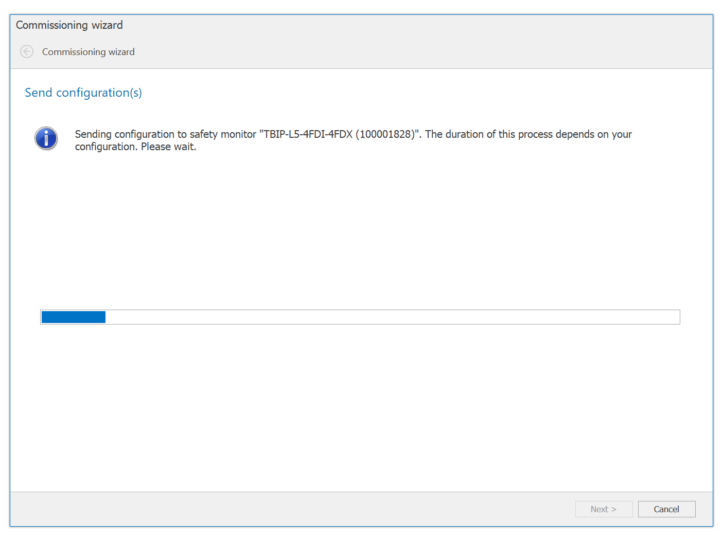
Send Configuraiton
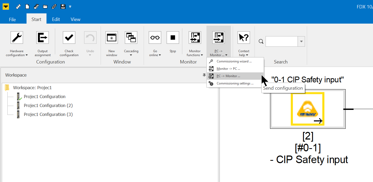
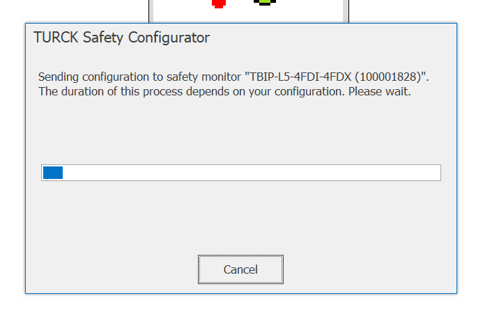
Finally, transfer the project to the module: click on Start>PC->Monitor.
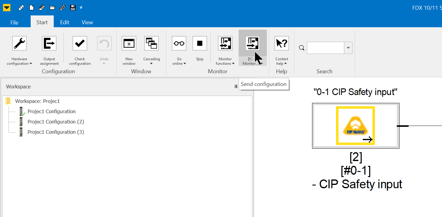
It is also possible to operate Upload projects from the Drop List.
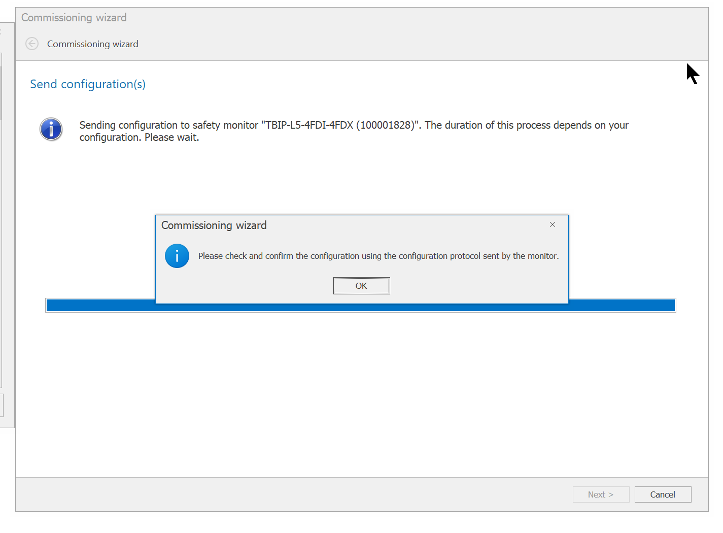
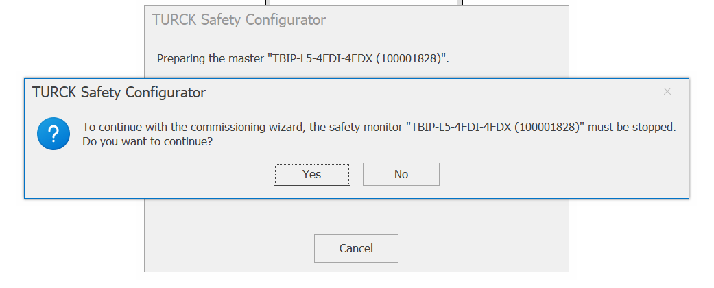
Proceed with Yes.
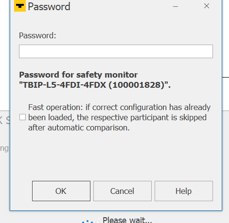
Enter the Password you have just set.
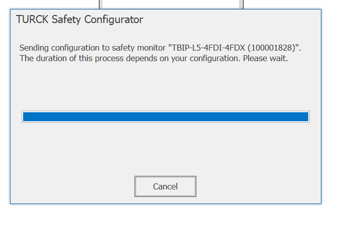
Just a while..
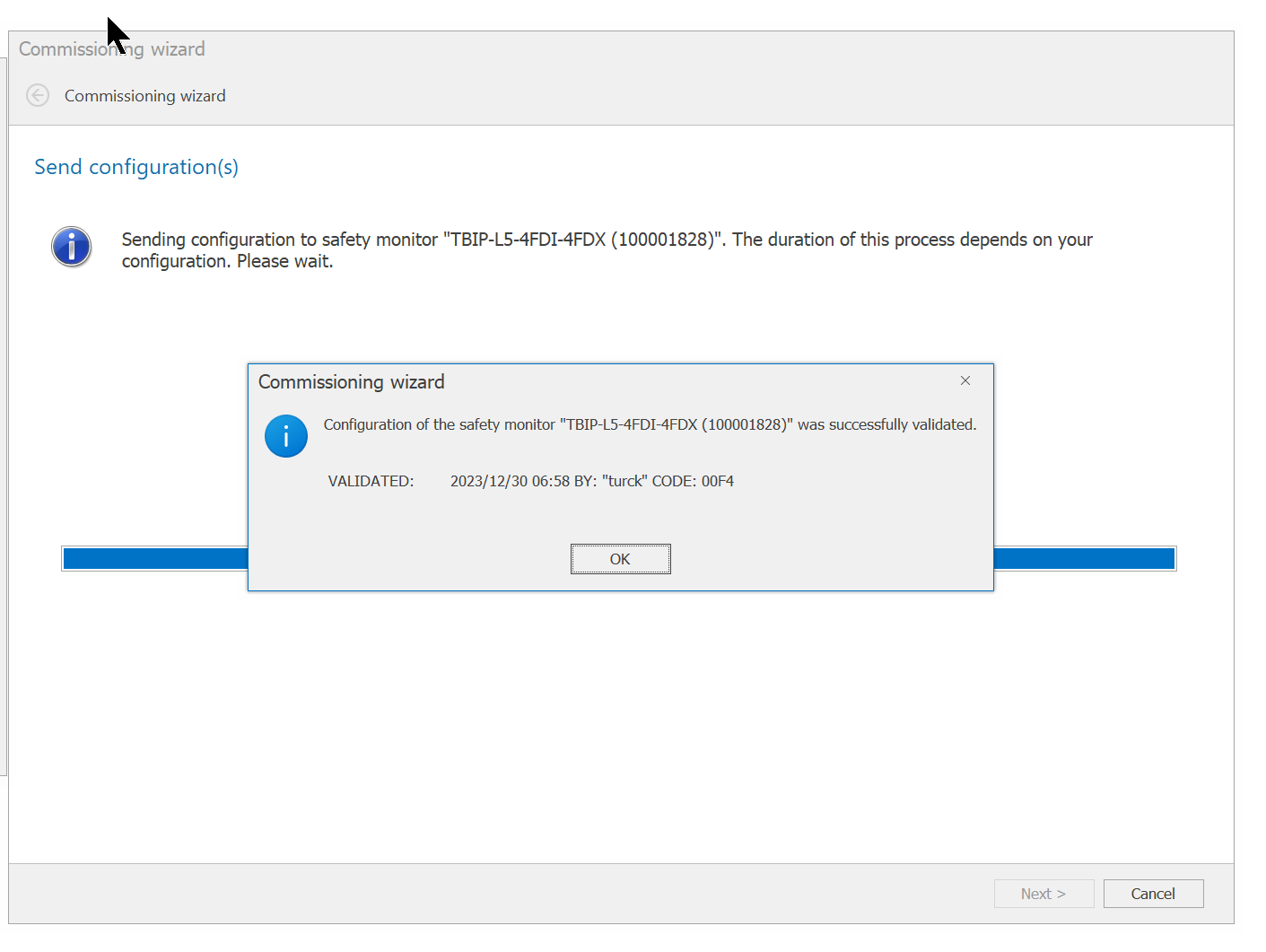
Done!
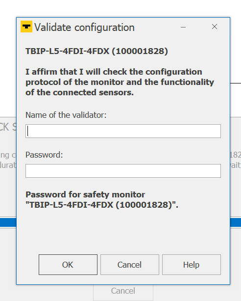
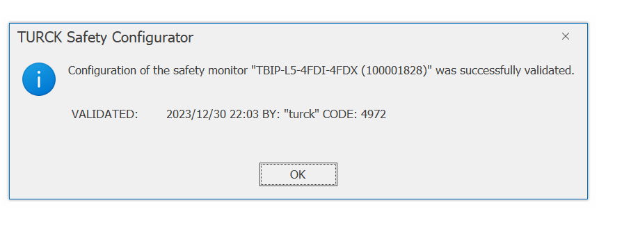
Finally, enter the Validator and Password again.
Just a While..
Done!
Go Online
Monitor the project in the Go line.
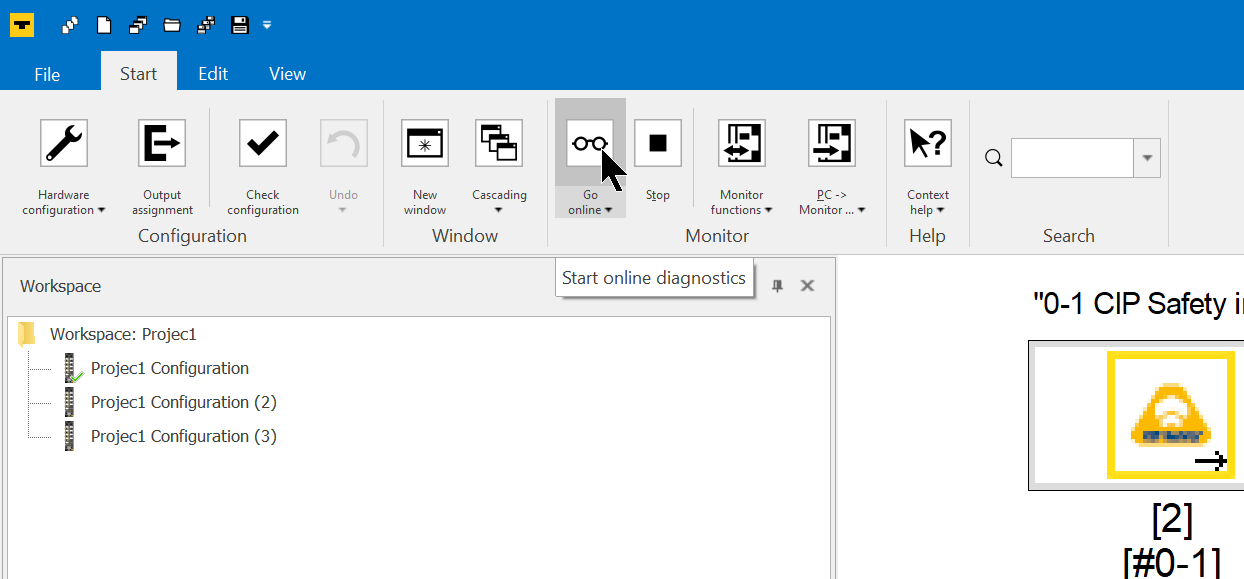
Done!
Omron Side
The next step is to build the Omron side.
Reference Link
Create EDS File
Create Turck’s TBIP-L5-4FDI-4FDX module Safety EDS File.
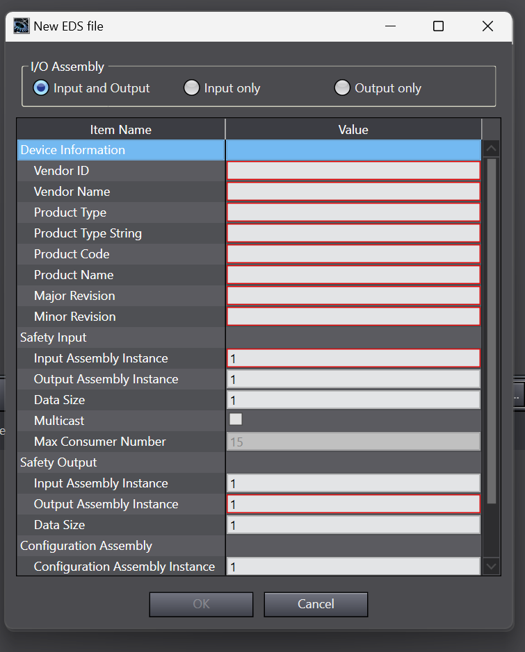
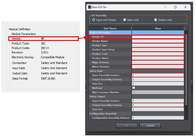
Vendor ID
The Vendor ID will be 48.
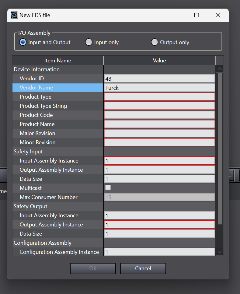
Vendor Name
The Vendor Name is actually affected by the organization and display of the EDS Library in Sysmac Studio, so enter as much correct information as possible.
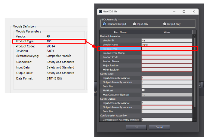
Product Type
Product Type will be 100.
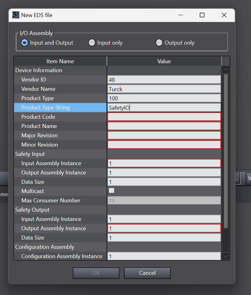
Product Type String
The Product Type String is actually affected by the organization and display of the EDS Library in Sysmac Studio, so enter as much correct information as possible.
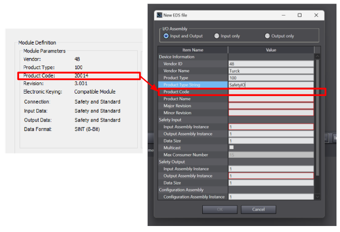
Product Code
Product Code is 20014.
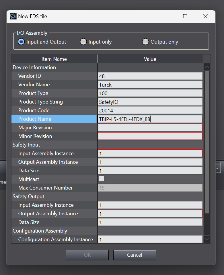
Product Name
The Product Name is actually affected by the organization and display of the EDS Library in Sysmac Studio, so enter as much correct information as possible.
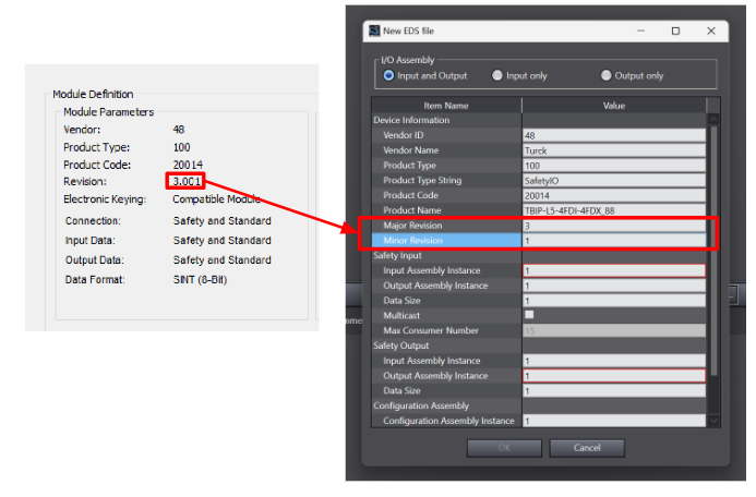
Revision
Major Revision is 3 and Minor Revision is 1.
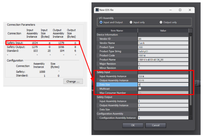
Safety Input
The Input Assembly Instance is 1024, the Output Assembly Instance is 1279 and the Data Size is 8 Bytes.
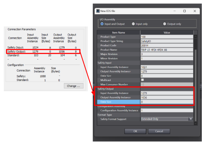
Safety Output
The Input Assembly Instance is 1279, the Output Assembly Instance is 1056 and the Data Size is 8 Bytes.
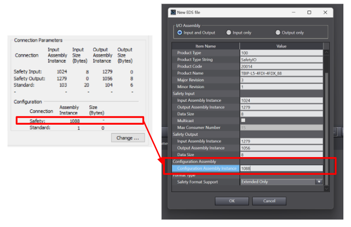
Configuration Instance
Configuration Instance will be 1088.
Add CIPSafety Devices
Next, let’s add the Turck CIP Safety module we defined earlier to the Network of Ethernet/IP.
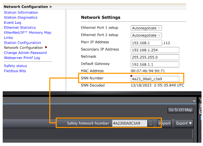
SNN Number
To use CIP Safety, a Safety Network Number must be set for the device.
Copy the Safety Network Number configured in Sysmac Studio,
Turck CIP Safety module and paste it under Web Server>Network Configuration>SNN Number.
Create Device Variable
Now select the Turck CIP Safety module from the I/O Map screen > right-click > Click Create Device Variable to automatically generate the variable.
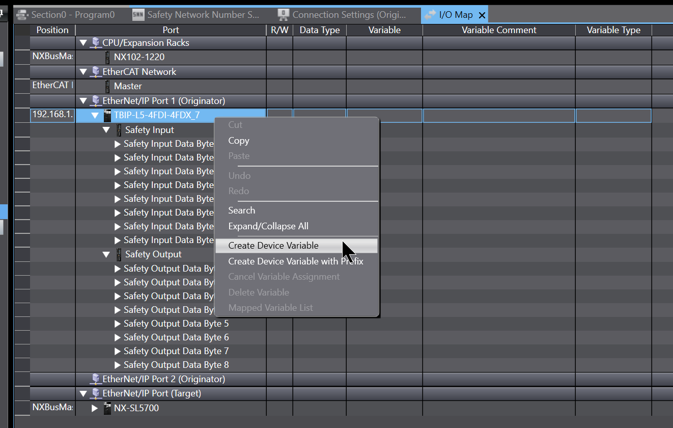
Done!
Add Ethernet/IP Connections
Besides the CIP Safety connection, the CIP Safety module from Turck also offers a Normal Ethernet/IP connection. In this article, CIP Safety communication and Normal Ethernet/IP are used to connect an OMRON NX-SL5700 and an NX CPU at the same time.
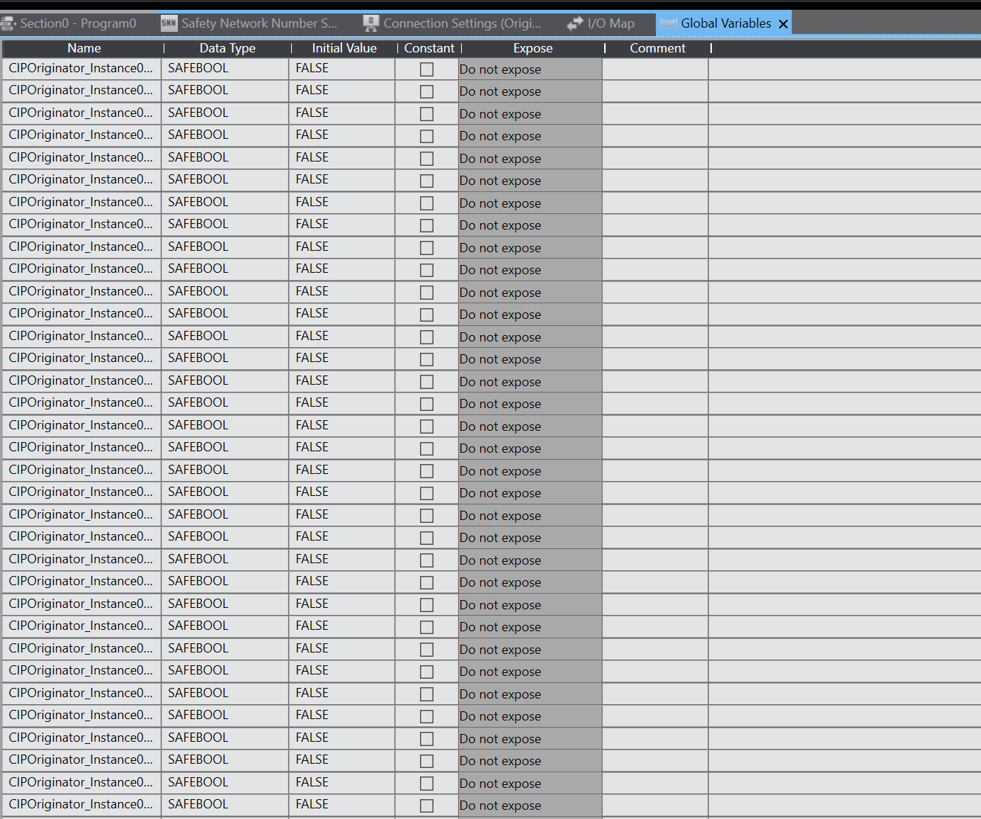
Define Global Variables
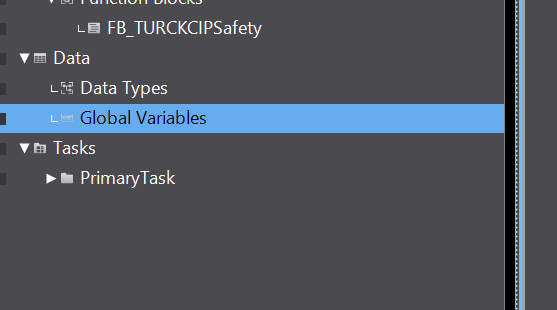
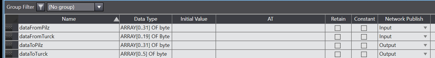
Open Data>Global Variables and define Global variables.
Define Byte arrays named dataFromTurck and dataToTurck.
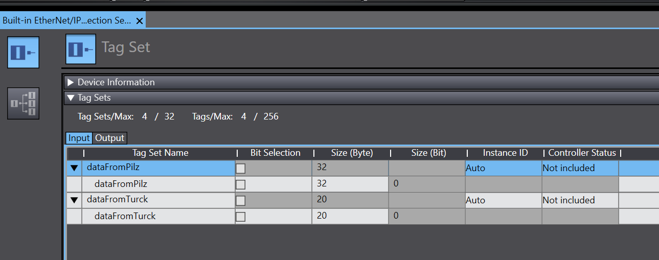
Register Variables
Register the variables defined earlier as Process Data for Etherent/IP.
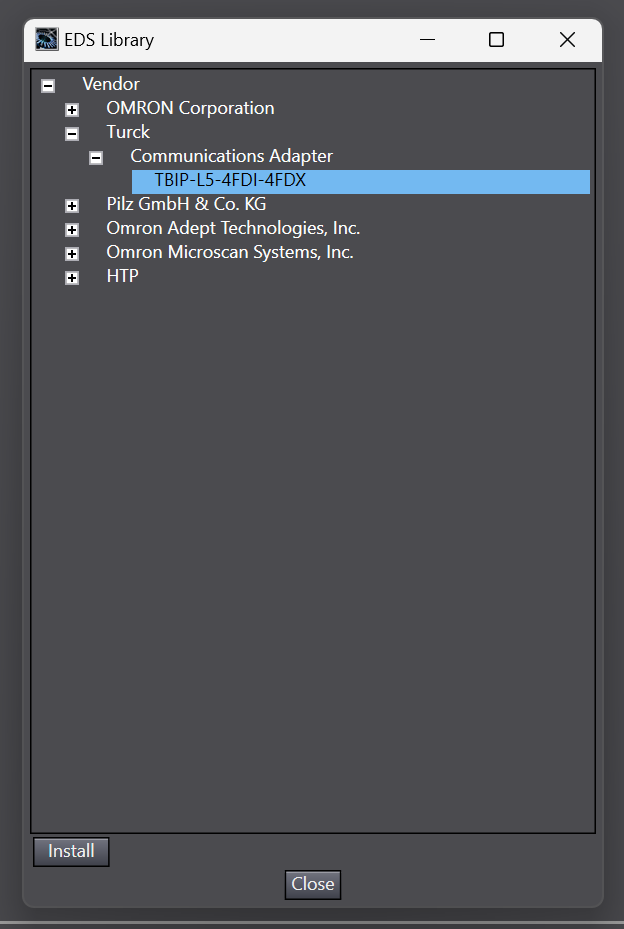
Install EDS File
Install the Donwloaded TBIP-L5-4FDI-4FDX EDS File from Turck HP.
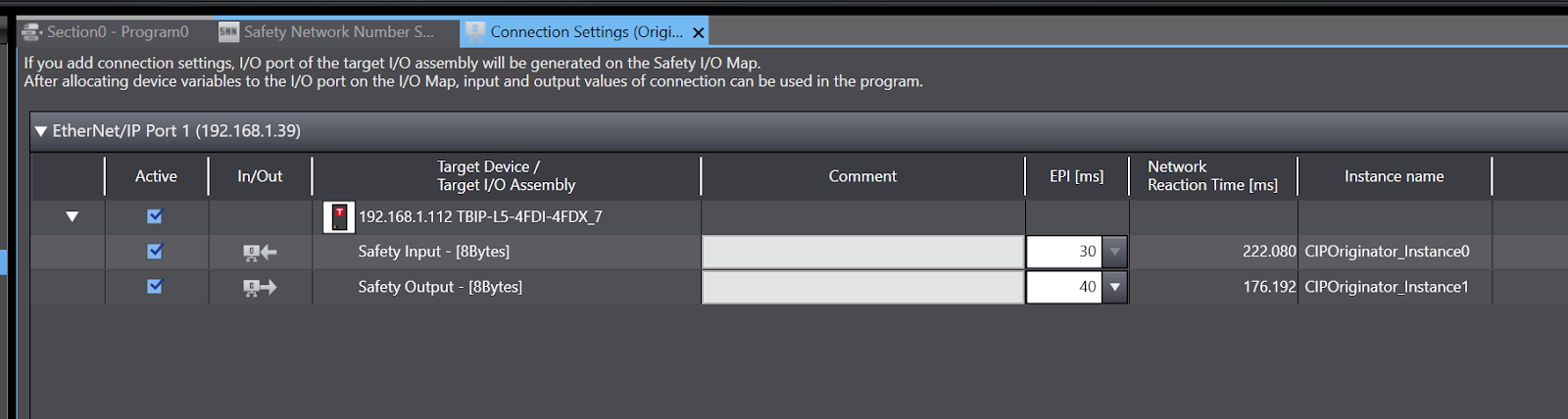
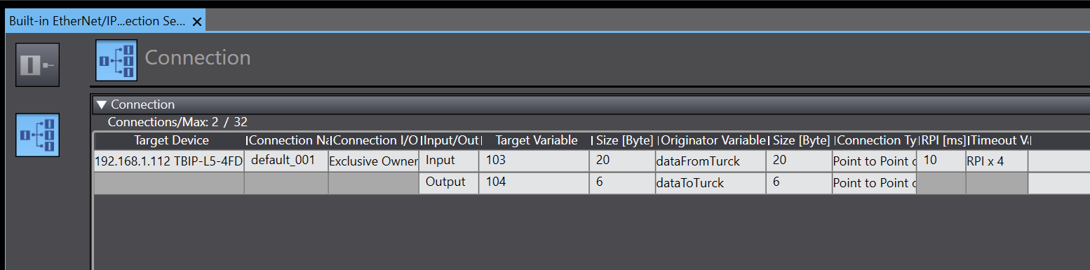
Add Connection
Define the Target device for TBIP-L5-4FDI-4FDX and add it to Connections.
Safety Program
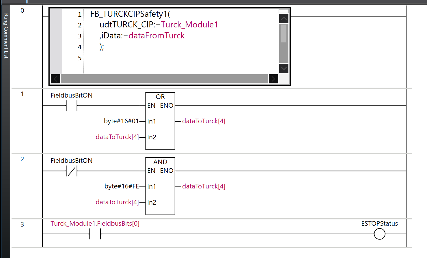
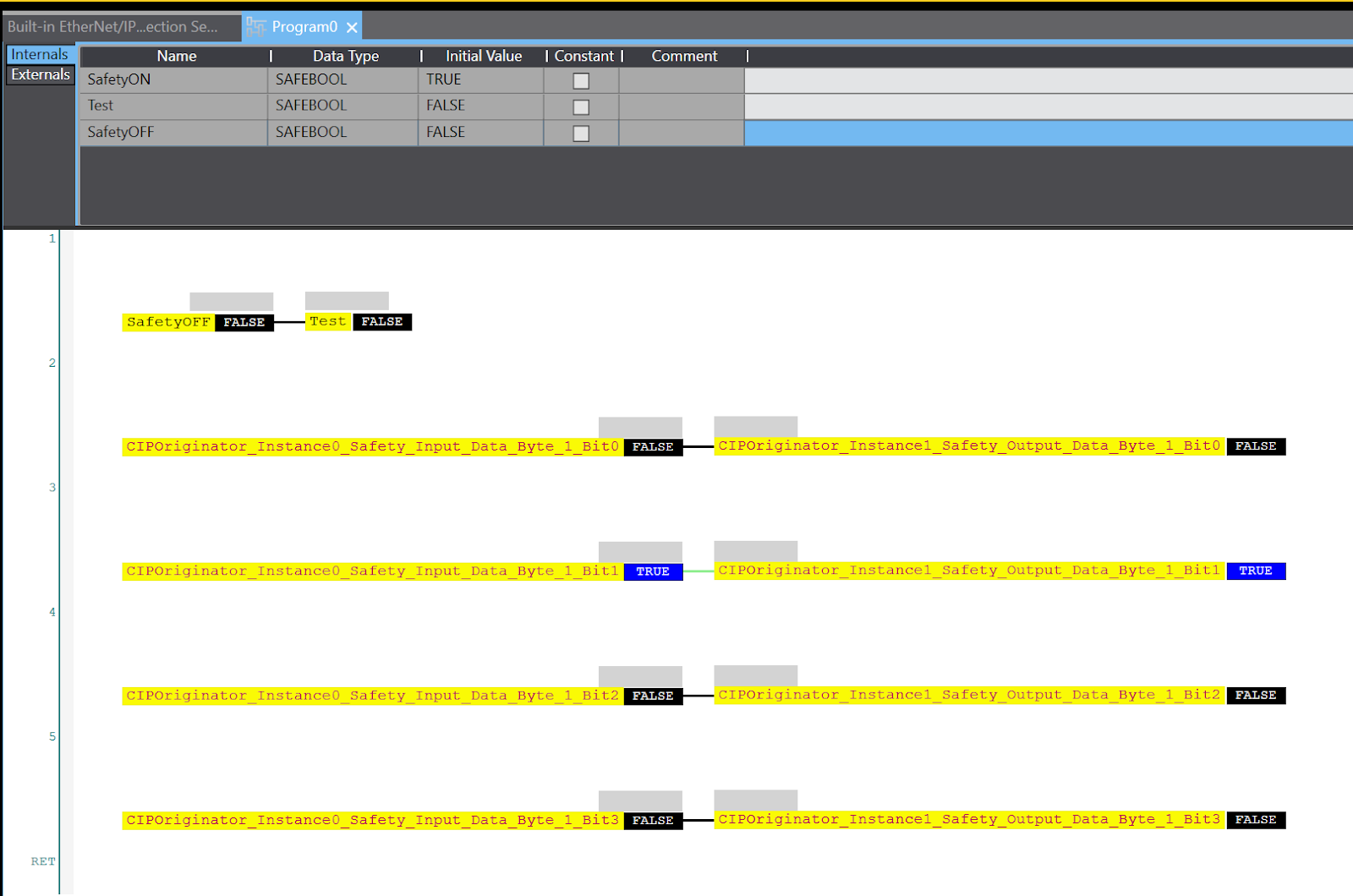
This is a safety programme on the part of Omron.
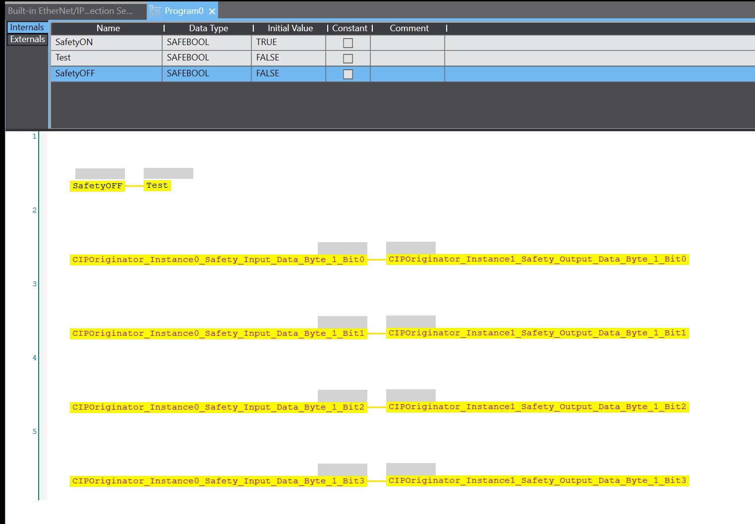
Normal Program
Data Types
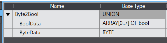
Byte2Bool
This is a Union type made so that each Bit of a Byte can be distributed to a Bool array.
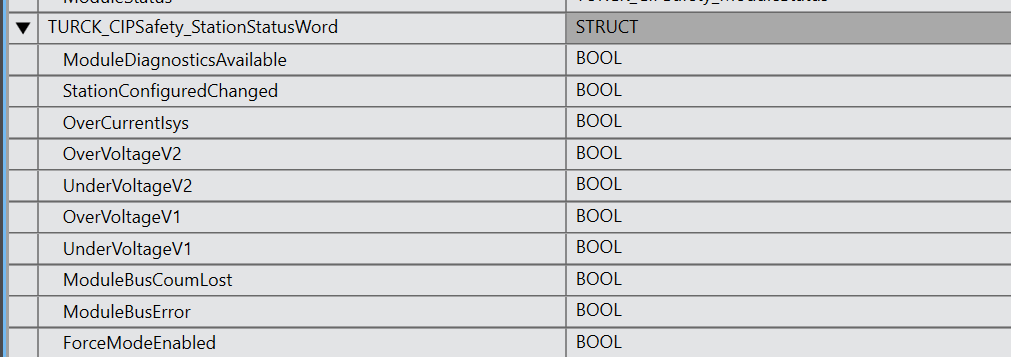
TURCK_CIPSafety_StationStatusWord
This is the structure of the Turck module state data that can be retrieved via the TURCK Etherent/IP Connection (Word offset 0).
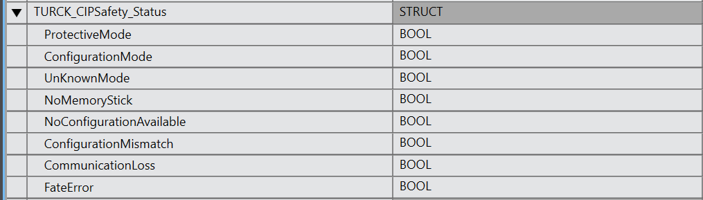
TURCK_CIPSafety_Status
This is the structure of the Turck module state data that can be retrieved via the TURCK Etherent/IP Connection (Word offset 1-3).
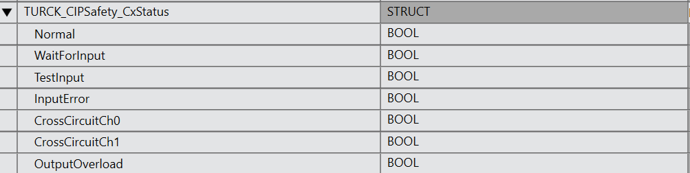
TURKC_CIPSafety_CxStatus
This is the structure of the Turck module state data that can be retrieved via the TURCK Etherent/IP Connection (Word offset 4-7).
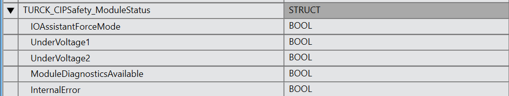
TURCK_CIPSafety_ModuleStatus
This is the structure of the Turck module state data that can be retrieved via the TURCK Etherent/IP Connection (Word offset 9).
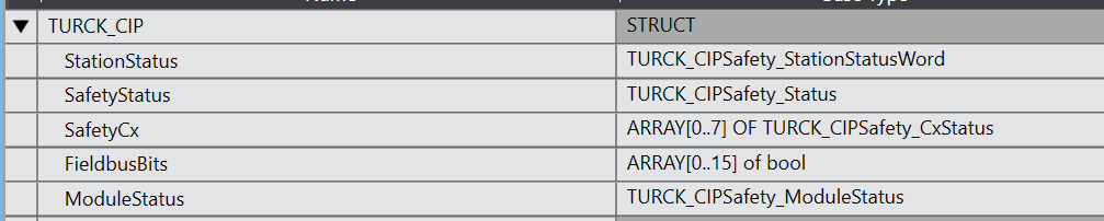
TURCK_CIP
This structure is a further grouping of the structures defined earlier.
Function
FC_GetCxStatus
In this FC, the Port state of the Turck module is decomposed from the Byte data.
In/Out
| EN Input BOOL iByte1 Input BYTE udtCxStatus In/Out TURCK_CIPSafety_CxStatus |
Internals
| uByte2Bool Byte2Bool |
Program
| uByte2Bool.ByteData:=iByte1; udtCxStatus.Normal:=uByte2Bool.BoolData[0]; udtCxStatus.WaitForInput:=uByte2Bool.BoolData[1]; udtCxStatus.TestInput:=uByte2Bool.BoolData[2]; udtCxStatus.InputError:=uByte2Bool.BoolData[3]; udtCxStatus.CrossCircuitCh0:=uByte2Bool.BoolData[4]; udtCxStatus.CrossCircuitCh1:=uByte2Bool.BoolData[5]; udtCxStatus.OutputOverload:=uByte2Bool.BoolData[7]; |
Function Block
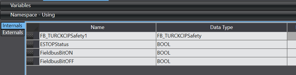
FB_TURCKCIPSafety
The Function Block here breaks down the input data (19Bytes) acquired via the Turck module and Ethernet/IP Connection into structures.
In/Out
| udtTURCK_CIP In/Out TURCK_CIP iData Input ARRAY[0..19] OF byte |
Internals
| uByte2Bool Byte2Bool |
Program
| uByte2Bool.ByteData:=iData[0]; //Station Status word uByte2Bool.ByteData:=iData[0];//word0 udtTURCK_CIP.StationStatus.ModuleDiagnosticsAvailable:=uByte2Bool.BoolData[0]; udtTURCK_CIP.StationStatus.StationConfiguredChanged:=uByte2Bool.BoolData[3]; udtTURCK_CIP.StationStatus.OverCurrentIsys:=uByte2Bool.BoolData[5]; udtTURCK_CIP.StationStatus.OverVoltageV2:=uByte2Bool.BoolData[6]; udtTURCK_CIP.StationStatus.UnderVoltageV2:=uByte2Bool.BoolData[7]; uByte2Bool.ByteData:=iData[1];//word0 udtTURCK_CIP.StationStatus.OverVoltageV1:=uByte2Bool.BoolData[0]; //8 udtTURCK_CIP.StationStatus.UnderVoltageV2:=uByte2Bool.BoolData[1]; //9 udtTURCK_CIP.StationStatus.ModuleBusCoumLost:=uByte2Bool.BoolData[2]; //10 udtTURCK_CIP.StationStatus.ModuleBusError:=uByte2Bool.BoolData[3]; //11 udtTURCK_CIP.StationStatus.ForceModeEnabled:=uByte2Bool.BoolData[6]; //14 //Safety Status uByte2Bool.ByteData:=iData[2];//word1 byte2,3 udtTURCK_CIP.SafetyStatus.ProtectiveMode:=uByte2Bool.BoolData[0]; udtTURCK_CIP.SafetyStatus.ConfigurationMode:=uByte2Bool.BoolData[1]; udtTURCK_CIP.SafetyStatus.UnKnownMode:=uByte2Bool.BoolData[2]; uByte2Bool.ByteData:=iData[4];//word2 byte4,5 uByte2Bool.ByteData:=iData[6];//word3 byte6,7 udtTURCK_CIP.SafetyStatus.NoMemoryStick:=uByte2Bool.BoolData[0]; udtTURCK_CIP.SafetyStatus.NoConfigurationAvailable:=uByte2Bool.BoolData[1]; udtTURCK_CIP.SafetyStatus.ConfigurationMismatch:=uByte2Bool.BoolData[2]; udtTURCK_CIP.SafetyStatus.CommunicationLoss:=uByte2Bool.BoolData[4]; udtTURCK_CIP.SafetyStatus.FateError:=uByte2Bool.BoolData[7]; uByte2Bool.ByteData:=iData[8];//word4 byte8 FC_GetCxStatus( EN:=TRUE ,iByte1:=iData[8] ,udtCxStatus:=udtTURCK_CIP.SafetyCx[0] ); uByte2Bool.ByteData:=iData[9];//word4 byte9 FC_GetCxStatus( EN:=TRUE ,iByte1:=iData[9] ,udtCxStatus:=udtTURCK_CIP.SafetyCx[1] ); uByte2Bool.ByteData:=iData[10];//word5 byte10 FC_GetCxStatus( EN:=TRUE ,iByte1:=iData[10] ,udtCxStatus:=udtTURCK_CIP.SafetyCx[2] ); uByte2Bool.ByteData:=iData[11];//word5 byte11 FC_GetCxStatus( EN:=TRUE ,iByte1:=iData[11] ,udtCxStatus:=udtTURCK_CIP.SafetyCx[3] ); uByte2Bool.ByteData:=iData[12];//word6 byte12 FC_GetCxStatus( EN:=TRUE ,iByte1:=iData[11] ,udtCxStatus:=udtTURCK_CIP.SafetyCx[4] ); uByte2Bool.ByteData:=iData[13];//word6 byte13 FC_GetCxStatus( EN:=TRUE ,iByte1:=iData[11] ,udtCxStatus:=udtTURCK_CIP.SafetyCx[5] ); uByte2Bool.ByteData:=iData[14];//word7 byte14 FC_GetCxStatus( EN:=TRUE ,iByte1:=iData[11] ,udtCxStatus:=udtTURCK_CIP.SafetyCx[6] ); uByte2Bool.ByteData:=iData[15];//word7 byte15 FC_GetCxStatus( EN:=TRUE ,iByte1:=iData[11] ,udtCxStatus:=udtTURCK_CIP.SafetyCx[7] ); uByte2Bool.ByteData:=iData[16];//word8 Byte16 udtTURCK_CIP.FieldbusBits[0]:=uByte2Bool.BoolData[0]; udtTURCK_CIP.FieldbusBits[1]:=uByte2Bool.BoolData[1]; udtTURCK_CIP.FieldbusBits[2]:=uByte2Bool.BoolData[2]; udtTURCK_CIP.FieldbusBits[3]:=uByte2Bool.BoolData[3]; udtTURCK_CIP.FieldbusBits[4]:=uByte2Bool.BoolData[4]; udtTURCK_CIP.FieldbusBits[5]:=uByte2Bool.BoolData[5]; udtTURCK_CIP.FieldbusBits[6]:=uByte2Bool.BoolData[6]; udtTURCK_CIP.FieldbusBits[7]:=uByte2Bool.BoolData[7]; uByte2Bool.ByteData:=iData[17];//word8 Byte17 udtTURCK_CIP.FieldbusBits[8]:=uByte2Bool.BoolData[0]; udtTURCK_CIP.FieldbusBits[9]:=uByte2Bool.BoolData[1]; udtTURCK_CIP.FieldbusBits[10]:=uByte2Bool.BoolData[2]; udtTURCK_CIP.FieldbusBits[11]:=uByte2Bool.BoolData[3]; udtTURCK_CIP.FieldbusBits[12]:=uByte2Bool.BoolData[4]; udtTURCK_CIP.FieldbusBits[13]:=uByte2Bool.BoolData[5]; udtTURCK_CIP.FieldbusBits[14]:=uByte2Bool.BoolData[6]; udtTURCK_CIP.FieldbusBits[15]:=uByte2Bool.BoolData[7]; uByte2Bool.ByteData:=iData[18];//word9 Byte18 udtTURCK_CIP.ModuleStatus.ModuleDiagnosticsAvailable:=uByte2Bool.BoolData[0]; udtTURCK_CIP.ModuleStatus.UnderVoltage2:=uByte2Bool.BoolData[7]; uByte2Bool.ByteData:=iData[18];//word9 Byte19 udtTURCK_CIP.ModuleStatus.UnderVoltage1:=uByte2Bool.BoolData[1]; udtTURCK_CIP.ModuleStatus.InternalError:=uByte2Bool.BoolData[2]; udtTURCK_CIP.ModuleStatus.IOAssistantForceMode:=uByte2Bool.BoolData[6]; |
MAIN
This is the Main programme, which calls the Function Block defined earlier and also sends the start-up signal of the Fieldbus Bit to the Turck module for safe unlocking.
Download
Finally, download the Safety project, Normal project and also the Ethernet/IP Connection settings to the NX CPU and reset the power supply.
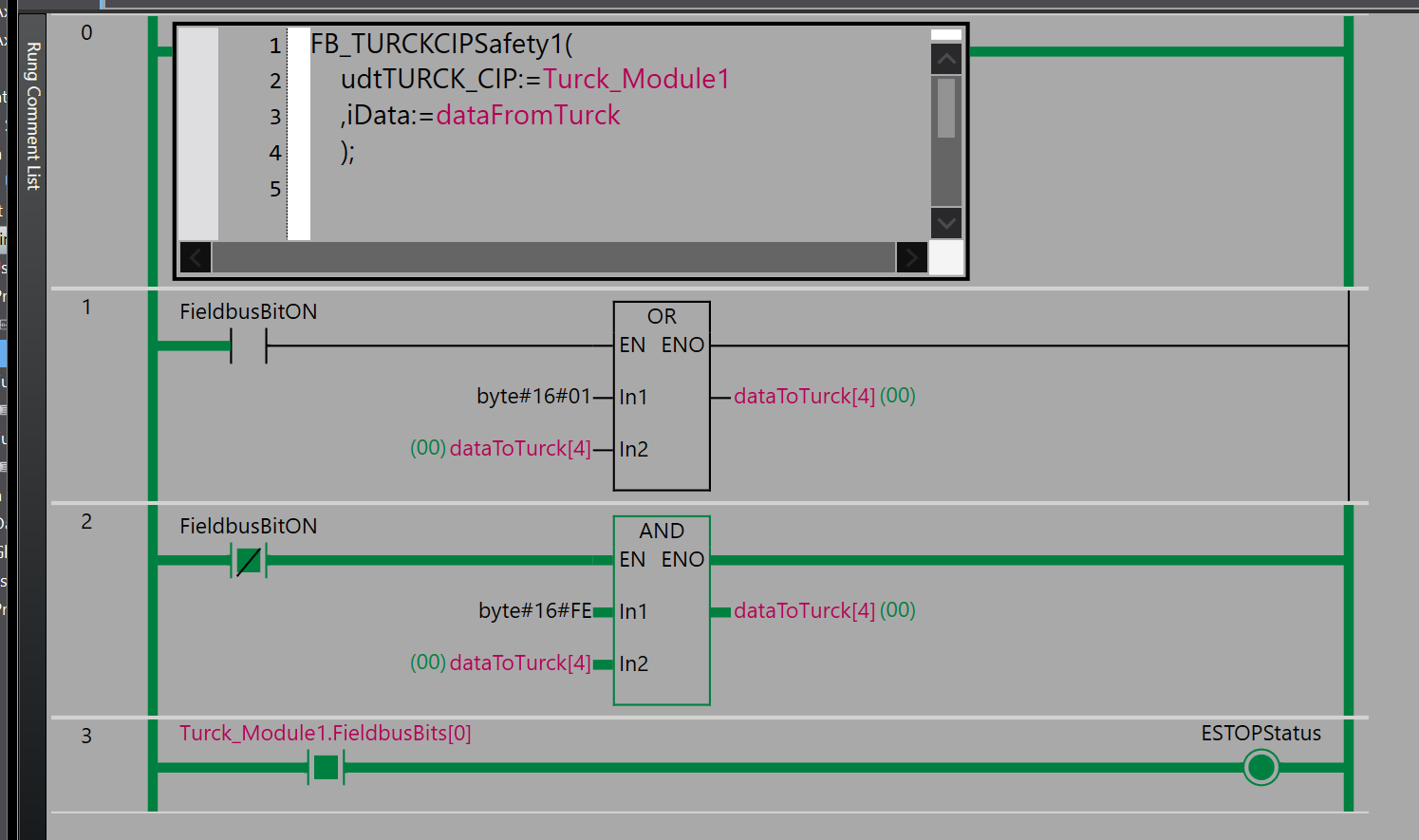
Result
Done!Safety input/output data could be exchanged via the Turck module and the CIP Safety connection.
An emergency stop condition was also taken via the Normal Ethernet/IP connection.
The current input/output status can also be monitored from the Turck Safety Configurator software.
This video shows the TURCK module via OMRON CIP Safety.
OMRON.CIP Safety Connection with TURCK Safety Blocks
You can see the Turck module in action in this video.
OMRON.Normal Condition of SL5700 and Turck Safety IO
You can check the OMRON safety programme status in this video.
OMRON.CIP Safety Connection with TURCK Safety Blocks Safety Program Side
Download EDS File
Download the Turck Safety EDS File for OMRON Sysmac Studio from this Link.
https://github.com/soup01Threes/OMRON/blob/main/0030_4E2E_TBIP-L5-4FDI-4FD_16B9A185.eds
Download Project
You can download a sample project of the article from this Link.
https://github.com/soup01Threes/OMRON/blob/main/CIPSafety_TURCK.smc2