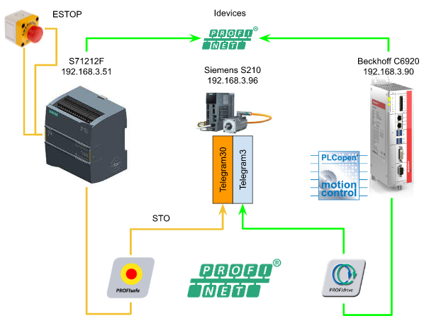
This is the 4th episode of running Siemens Sinamics S210 from Beckhoff TwinCAT3. Last time, I used the PLCOPEN library to operate the Drive, but there was no direct communication between the S7-1200 and Beckhoff IPC, I couldn’t get the STO reset signal or the status of the S7-1200, The rest operation can only be operated on the S7-1200 Side.
Profinet has a function called I-Devices, which allows the S7-1200 to work as Devices for other Controllers while being a Controller. In this article, I will introduce its functions, how to configure it , create a program to acquire diagnostic information of S7-1200 and S210, and pass it to Beckhoff IPC.
Thanks!
Because of Beckhoff Japan and mana Design works that lend the devices to me – I can create this post.
Beckhoff Japan
IPC6920-005 was lent by Beckhoff Japan, a Japanese subsidiary of Beckhoff. Founded in 1980, Beckhoff Automation is a German company at the forefront of the introduction of open automation systems based on PC-based control technology.
Beckhoff Japan Corporation Beckhoff Automation Co., Ltd. established its head office in Yokohama in 2011 and the Nagoya office in 2017.

Here is the Home page of Beckhoff Japan.
https://www.beckhoff.com/ja-jp/
Mana Design Works
Siemens SINAMICS S210 was lent by Mana Design Works.
Mana Design Works is an official solution partner of Siemens ,headquartered in Osaka, and always make optimal proposals with Siemens CPUs, HMIs, Drives, Motion Controllers, and SCADA.

Here is the homepage of Mana Design works.
Video
English Version
Part4
Beckhoff.TwinCAT3 x Siemens S210 Servo Drive part4 – Idevices Configuration.EN
Part3
Beckhoff.TwinCAT3 x Siemens S210 Servo Drive part3 – PLCOPEN to Control the Drive in TwinCAT.EN
Part2
Beckhoff.TwinCAT3 x Siemens S210 Servo Drive part2 – Shared Devices,Profisafe.EN
Part1
Beckhoff.TwinCAT3 x Siemens S210 Servo Drive part1.EN
Japanese Version
Part4
Beckhoff.TwinCAT3 x Siemens S210 Servo Drive part4 – Idevices Configuration.JP
Part3
Beckhoff.TwinCAT3 x Siemens S210 Servo Drive part3 – PLCOPEN to Control the Drive in TwinCAT.JP
Part2
Beckhoff.TwinCAT3 x Siemens S210 Servo Drive part2 – Shared Devices,Profisafe.JP
Part1
Beckhoff.TwinCAT3 x Siemens S210 Servo Drive part1.JP
Reference Link
Japanese Version
Project#Beckhoff TwinCAT3 x Siemens S210 Servo Drvie_Part2 |
English Version
Project#Beckhoff TwinCAT3 x Siemens S210 Servo Drvie_Part2 |
Project#Beckhoff TwinCAT3 x Siemens S210 Servo Drvie_Part1 |
Implementation
Siemens Side
Let’s start on the Siemens side first.
I-Devices
Go to S71200>PROFINET Interface[x1]>Operating Mode and check the IO Device checkbox.

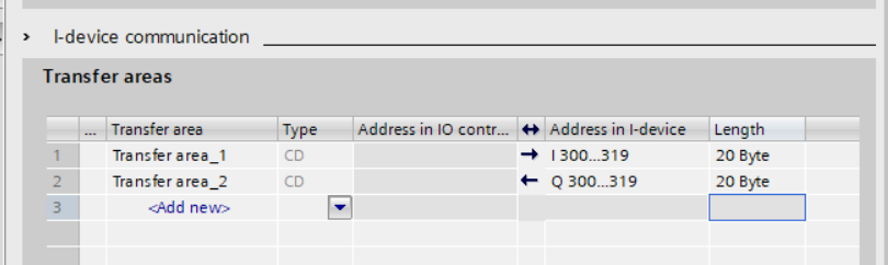
i-device communication is shown and you can insert the exchange area by clicking the <Add new> Button.

Transfer area_1 and Transfer area_2 that started from I300.0/Q300.0,20 bytes are configured.
IP
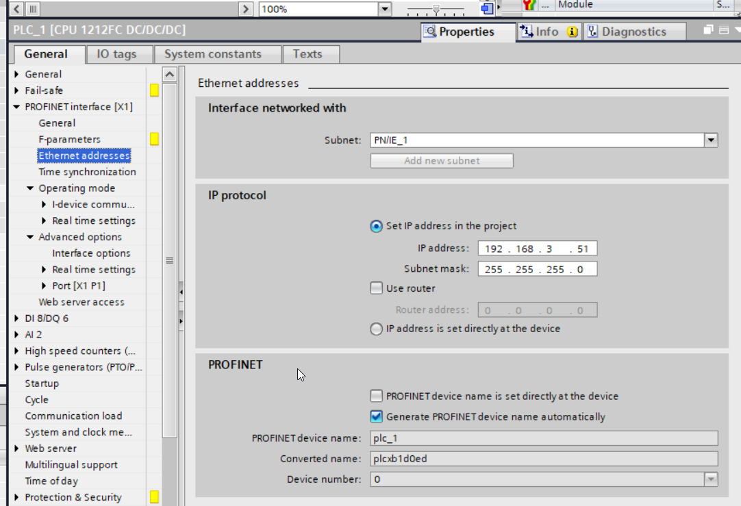
Go to PROFINET interface[X1]>Ethernet addresses to configure the IP address and Profinet setting for your S7-1200.
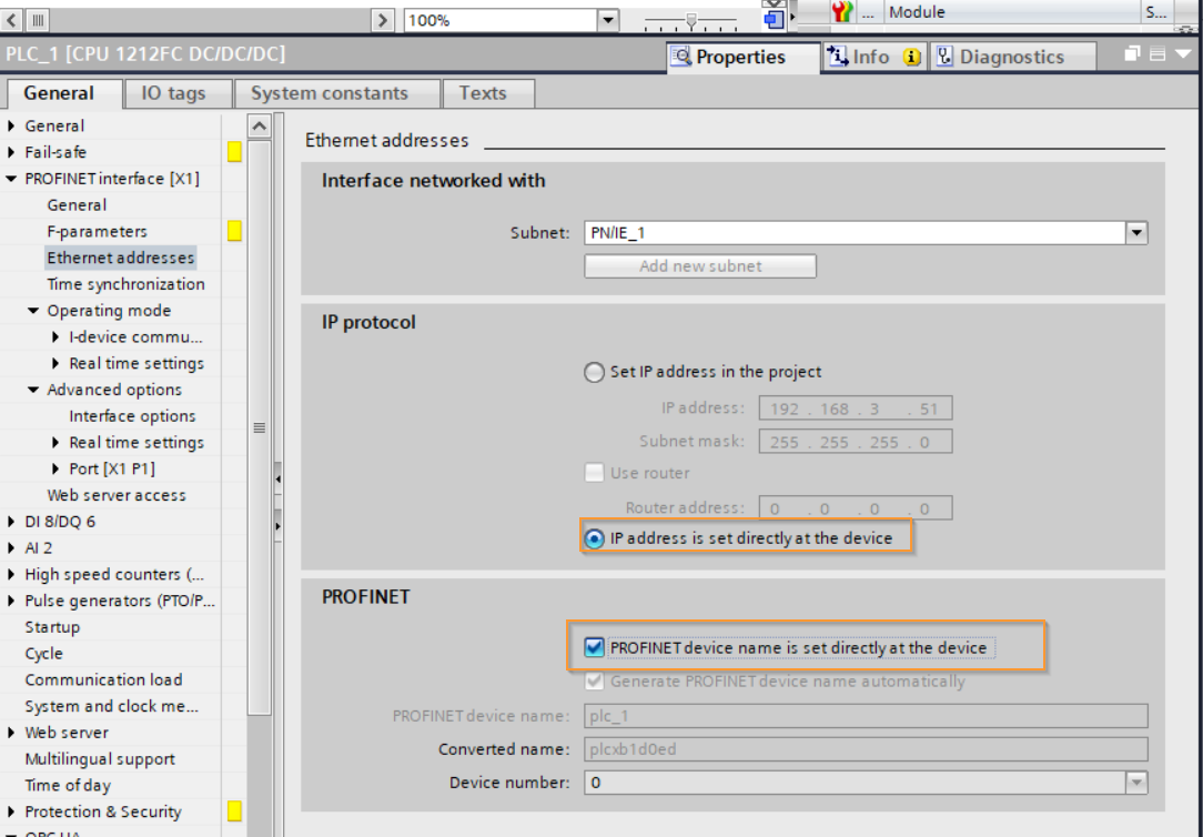
Check the “IP address is set directly at the device” Box.
Export GSDML
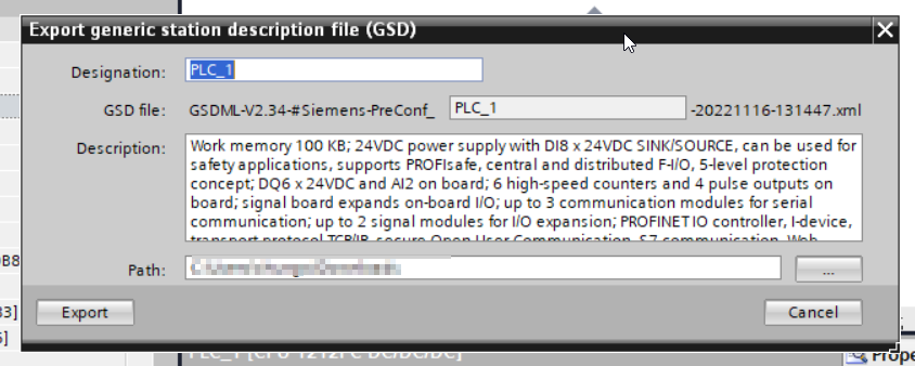
Press the Export button to Export the GSDML file.
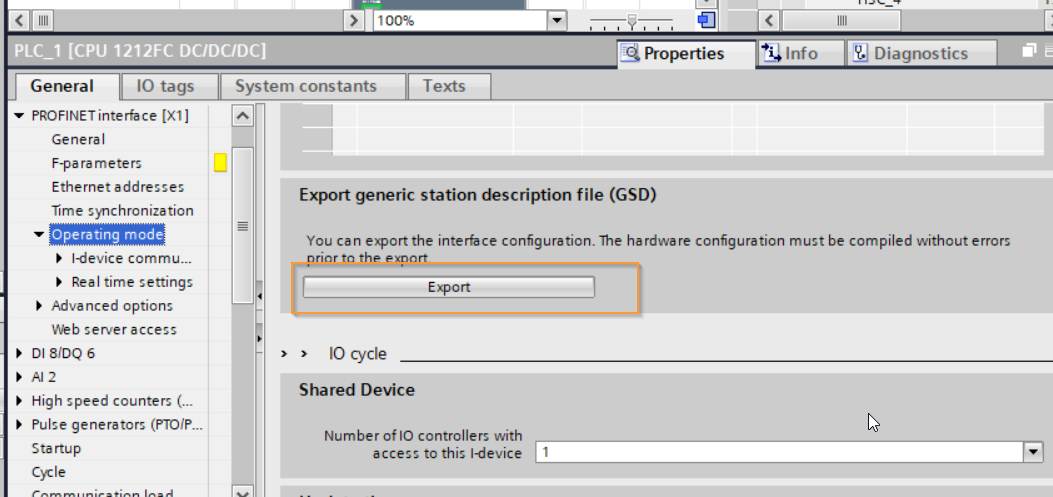
Setup your Export path and start the export.
Add OB
Insert OB82/OB83/OB86 to prevent CPU shift to stop mode because of IO failure Error.

OB82? Diagnostic error interrupt OB
Modules with diagnostic capabilities will notify the CPU when the diagnostic state changes. The notification is a “diagnostic interrupt request”.
When an Event comes, the OB82’s Local tag will contain diagnostic data.
If there is no OB82 in the CPU, the CPU switches to Stop Mode.
There are some functions that control OB82.
Disable that OB82 with the DIS_IRT function.
Enable that OB82 with the EN_IRT function.
The DIS_AIRT function is a Delay of DIS_IRT.
The EN_AIRT function is a Delay of EN_IRT.
OB83?
OB83 is called due to:
- A configured module is inserted/ejected.
- When a module parameter is changed and downloaded from Step 7 while the CPU is in the Run state
If there is no OB83 in the CPU, the CPU switches to Stop Mode.
Its OB83 can be controlled by SFC39 to 42.
OB86?
OB86 is the Rack Failure Organization Block and is called due to:
- When the DP Master System detects an error
- When a distributed IO error is detected
If there is no OB86 in the CPU, the CPU switches to Stop Mode.
There are functions that control OB86.
SFC 12 “D_ACT_DP” setting MODE=4, Disable Station
SFC 12 “D_ACT_DP” setting MODE=3, Enable Station
Startup Condition
Go to General>Startup>Select “Startup CPU even if mismatch” option.
The CPU can go to run mode although the Hardware configuration is not the same as the real installation.

LLDP V2.2?V2.3
LLDP is the “Link Layer Discovery Protocol”, a standard protocol of IEEE-802.1AB.
Profinet Devices periodically send their information to devices connected with LLDP Protocol. Next, SNMP (Simple Network Management Protocol) reads the LLDP information and creates Network Topology.
Basically standard IEC61158 V2.2 is implemented in Profinet devices,but some Profinet devices implement the new LLDP Protocol (V2.3),
Siemens and others detect Profinet Devices in its V2.3.
Note that the LLDP version must be standardized within the Profinet network.
If you build all your Profinet instruments with TIA, Step7 automatically modifies the LLDP Modes so you don’t have to worry about setting them up.
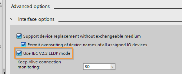
The Use IEC V2.2 LLDP mode checkbox is not checked by default.
If Use IEC V2.2 LLDP mode is selected and cannot be changed, the PROFINET network will only support LLDP V2.2.
If the Use IEC V2.2 LLDP mode checkbox is disabled but can be changed, the PROFINET network is OK with both LLDP V2.2 and V2.3.
There are simple rules for its setting.
If all Devices are IEC V2.3 Support, Step7 will automatically switch Subnet Mode to IEC V2.3.If only one Device supports only IEC V2.2, Step7 will force Subnet Mode to V2.2.
Function Blocks
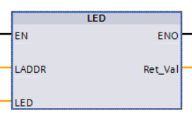
LED
You can get the LED status of the module by using this Function “LED”. (e.g. ON/OFF/Flashing)
In the LADDR parameter, put the interface variable of the CPU or module.
RET_VAL is the Return value of Function and returns the execution result of the function. Please refer to the manual of the module that acquired the status, as there are occasional LEDs that are not compatible.
VAR_INPUT
| Variable Name | Type | Description |
| LADDR | HW_IO | Identifier of Hardware Interface, (CPU name + to Common for CPU) |
| LED | UINT | LED identifier, 1=STOP/RUN, 2=Error, 3=MAINT, 5=Link, 6=Rx/Tx |
Return Value
| Variable Name | Type | Description |
| RET_VAL | INT | LED status (Please refer to TIA Help for details) |
GET_DIAG
You can use the GET_DIAG function here to get diagnostic information for hardware components. You can also select the diagnostic information you want to obtain from the MODE parameter. By the way, in the S7-1200 used in this article, the LADDR parameter is disabled when MODE=0.

This article uses Mode=1. By setting Mode=1、 the function’s output diagnostic information changes to a DIS structure.
VAR_INPUT
| Variable Name | Type | Description |
| Mode | UINT | Select the diagnostic information you want to acquire |
| LADDR | HW_ANY | hardware part identifier |
VAR_OUTPUT
| Variable Name | Type | Description |
| CNT_DIAG | UINT | Always=0 |
VAR_IN_OUT
| Variable Name | Type | Description |
| DIAG | VARIANT | Please refer to TIA Help for diagnostic information and details. |
| DETAIL | VARIANT | Not Used |
Return Value
| Variable Name | Type | Description |
| RET_VAL | INT | function state |
MODE
| Mode | Description | DIAG |
| 0 | 該当するモジュールがSupportするModeを取得します。 | Bit0= Mode0 SupportBit1=Mode1 SupportBit2=Mode2 SupportBit3-31=Spare |
| 1 | 該当するモジュールの診断情報を取得する | DIS StructureMaintenanceStateComponentStateOwnStateIOStateOperatingState(Refer to TIA Help) |
| 2 | 該当するモジュールのSubordinate部品情報を取得する | DNN StructureSubordinateStateSubordinateIOStateDNNMode(Refer to TIA Help) |
Program
UDT
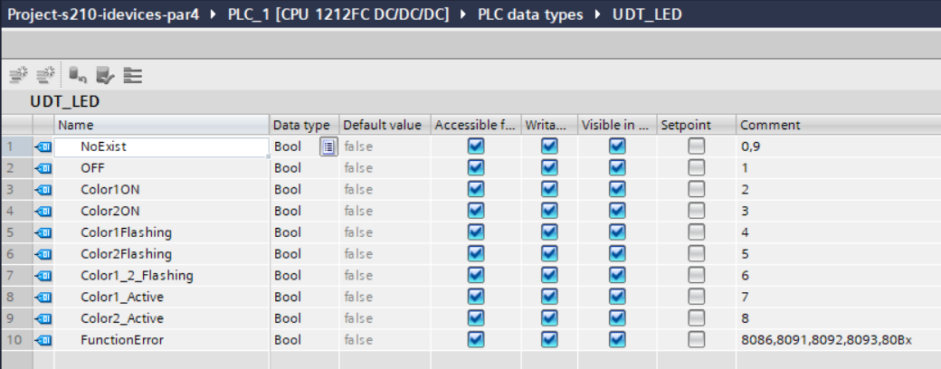
UDT_LED
Here is a Structure Data type to group the result of LED Function.
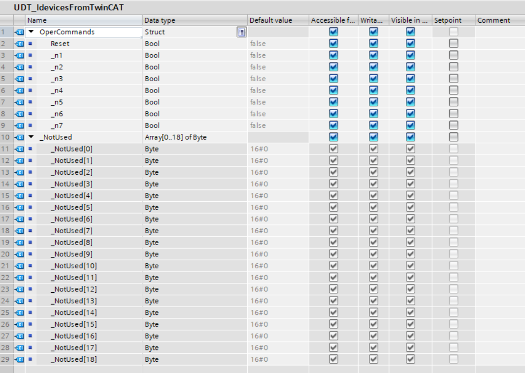
UDT_IdevicesFromTwinCAT
This is a structure that summarizes the data received from TwinCAT.
UDT_Idevices2TwinCAT
This is a structure that summarizes the data to be sent to TwinCAT.

Tags
Open the Tags Table and define I300.0 and Q300.0 as the Idevices data area and set the Data type as we defined before.

DB
Open DB_Shared to create the Receive buffer and STO data.

Function
FC_Get_LEDStatus
This function sets the corresponding bit to True according to the current value of LED Status obtained from the function.

| REGION init #FC_Get_LEDStatus.Color1_2_Flashing := False; #FC_Get_LEDStatus.Color1_Active := false; #FC_Get_LEDStatus.Color1Flashing := false; #FC_Get_LEDStatus.Color1ON := False; #FC_Get_LEDStatus.Color2_Active := False; #FC_Get_LEDStatus.Color2Flashing := False; #FC_Get_LEDStatus.Color2ON := False; #FC_Get_LEDStatus.FunctionError := false; #FC_Get_LEDStatus.NoExist := False; #FC_Get_LEDStatus.OFF := False; END_REGION REGION ReturnData CASE #LED OF 0,9: #FC_Get_LEDStatus.NoExist := True; 1: #FC_Get_LEDStatus.OFF := True; 2: #FC_Get_LEDStatus.Color1ON := True; 3: #FC_Get_LEDStatus.Color2ON := True; 4: #FC_Get_LEDStatus.Color1Flashing := True; 5: #FC_Get_LEDStatus.Color2Flashing := True; 6: #FC_Get_LEDStatus.Color1_2_Flashing := True; 7: #FC_Get_LEDStatus.Color1_Active := TRUE; 8: #FC_Get_LEDStatus.Color2_Active := TRUE; ELSE: #FC_Get_LEDStatus.FunctionError := True; ; END_CASE; END_REGION |
Function Block
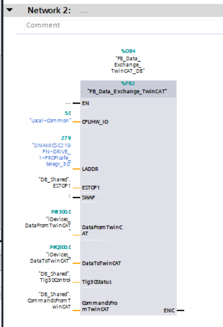
FB_Data_Exchange_TwinCAT
This is a Function Block that sends to/receives from TwinCAT.

We will get the ESTOP Status>CPU RUN/STOP ・MAINT・ERROR LED Status>S210 diagnostic information > Profisafe 30 in sequence, and finally the data received from TwinCAT is transferred to Buffer and used in other programs .
| REGION ESTOP #DataToTwinCAT.ESTOP1 := #ESTOP1; END_REGION REGION LED #LEDStatus.RUNSTOP := “FC_Get_LEDStatus”(LED := LED(LADDR := #CPUHW_IO, LED := #cLED_RUNSTOP)); #LEDStatus.ERROR := “FC_Get_LEDStatus”(LED := LED(LADDR := #CPUHW_IO, LED := #cLED_ERROR)); #LEDStatus.MAINT := “FC_Get_LEDStatus”(LED := LED(LADDR := #CPUHW_IO, LED := #cLED_Maint)); #DataToTwinCAT.CPU.RUN := #LEDStatus.RUNSTOP.Color1ON; #DataToTwinCAT.CPU.ERROR := #LEDStatus.ERROR.Color1Flashing OR #LEDStatus.ERROR.Color1ON; #DataToTwinCAT.CPU.MAINT := NOT #LEDStatus.MAINT.OFF; END_REGION REGION DIS #ReturnValue_GET_DIAG:=GET_DIAG(MODE := #CGET_DIAD_DIS, LADDR := #LADDR, CNT_DIAG => #CNT_DIAG, DIAG := #DIS); IF #SWAP THEN #DataToTwinCAT.DIS.ComponentStateDetail := SWAP(#DIS.ComponentStateDetail); #DataToTwinCAT.DIS.IOState := SWAP(#DIS.IOState); #DataToTwinCAT.DIS.MaintainanceState := SWAP(#DIS.MaintainanceState); #DataToTwinCAT.DIS.OperatingState := SWAP(#DIS.OperatingState); #DataToTwinCAT.DIS.OwnState := SWAP(#DIS.OwnState); END_IF; #DataToTwinCAT.CPU.internalEventAcknowledge := #Tlg30Status.internalEventAcknowledge; #DataToTwinCAT.CPU.STO := #Tlg30Status.STO; #DataToTwinCAT.CPU.SLS := #Tlg30Status.SLS; #DataToTwinCAT.CPU.SS1 := #Tlg30Status.SS1; #DataToTwinCAT.CPU.SLT := #Tlg30Status.SLT; END_REGION REGION DataFromTwinCAT #CommandsFromTwinCAT := #DataFromTwinCAT; END_REGION |
ADD OB1
Next, call FB_Data_Exchange_TwinCAT in OB1 and assign the parameters.
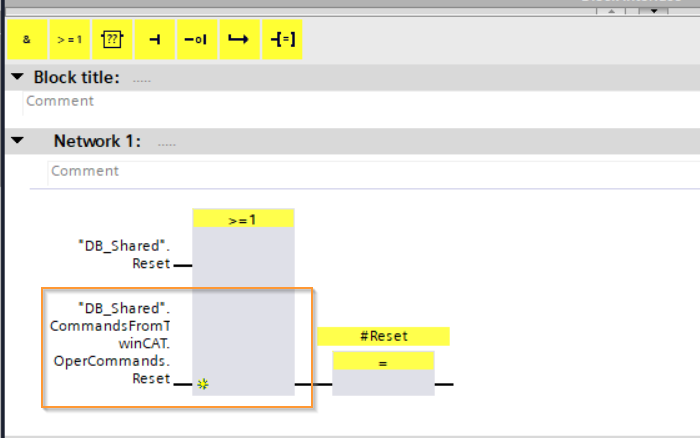
Safety
Now let’s modify the Safety program. Insert the Reset Signal only for Local in the Siemens S71200 >=1 OR Block, and insert the Reset signal from TwinCAT.
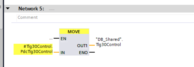
Transfer the Telegram 30 Control Status to TwinCAT.
Finally, add the ACK_GL Function Block. This is a Function Block that Globally resets Safety errors.

TwinCAT3 Side
Next up is the Beckhoff TwinCAT side.
Add S71200
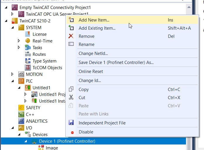
Go to Profinet Controller>Right Click >Add New Item.
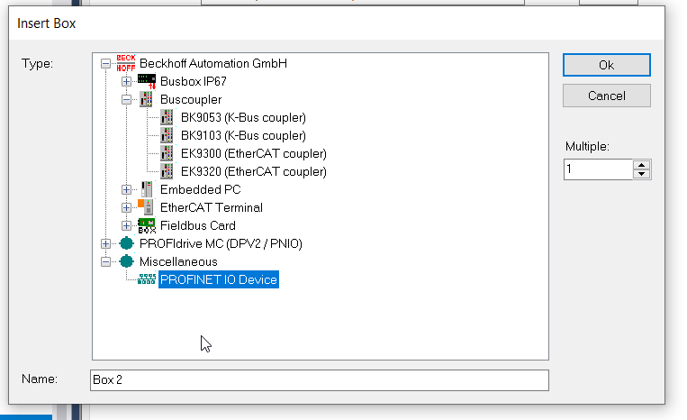
Go to Miscellaneous>Choose PROFINET IO Device>Ok.
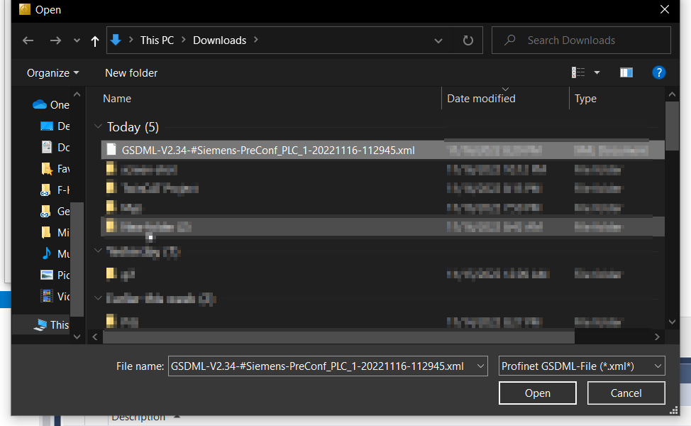
Select the GSDML File exported earlier and click >Open.
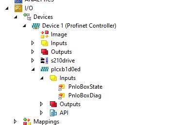
S7-1200 is inserted.

Change IP
Set the IP Configuration from the Device Tab. As I mentioned before, Profinet distributes IP from IO Controller by Device name.
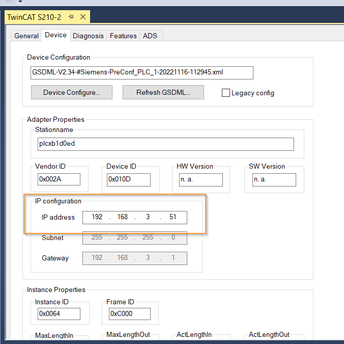
Change Device Name
Next, you can change the Device Name in the Name field of the General Tab.

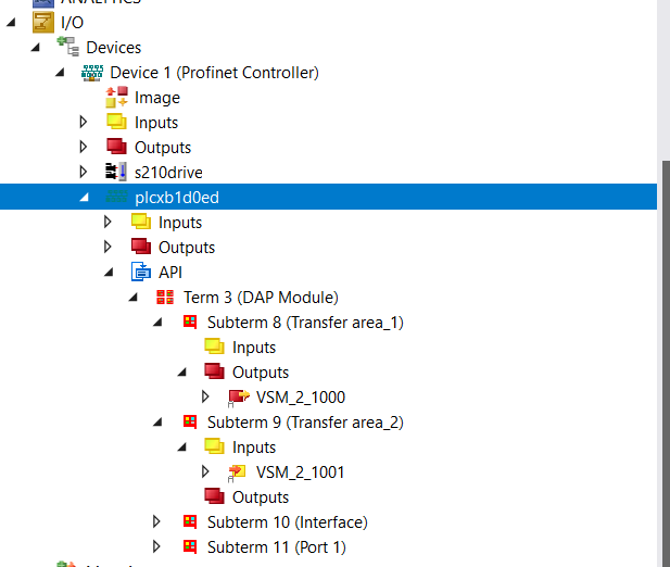
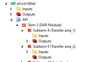
Mapping
Expanding the API of the S7-1200, there are Transfer area_1 and Transfer area_2. This is the same as the Transfer area name set in Siemens TIA.
Program
DUT
DUT_Data_FromSiemens_DIS_ComponentStateDetail
Here is the DUT that structured the data received from S7-1200 with the Component State Detail in the DIS variable.
| TYPE DUT_Data_FromSiemens_DIS_ComponentStateDetail : STRUCT QualifiedDiagnosticsAvailable :BIT; MaintenanceRequired :BIT; ErrorRequired :BIT; HardwareAvailable :BIT; ApplicationReadyPending :BIT; LockedBySuperordinated :BIT; LockedByIOController :BIT; LockedByIOSupervisor :BIT; OK :BIT; Substitute :BIT; Wrong :BIT; NoSubmodule :BIT; ModuleDisable :BIT; CiROperationActive :BIT; InputNotAvailable :BIT; OutputNotAvailable :BIT; OverFlowDiagnosticsFlow :BIT; DiagnosticsNotAvailable :BIT; PartialDeviceFailure :BIT; _n1,_n2,_n3,_n4,_n5,_n6,_n7 :BIT; _n8,_n9,_n10,_n11,_n12,_n13 :BIT; END_STRUCT END_TYPE |
DUT_Data_FromSiemens_DIS_IOStates
Here is the DUT that structured the data received from S7-1200 with the IO State In the DIS variable.
| TYPE DUT_Data_FromSiemens_DIS_IOStates : STRUCT Good :BIT; Disabled :BIT; MaintenanceRequired :BIT; MaintenanceDemanded :BIT; NotAccessible :BIT; QualifiedDiagnosticsAvailable :BIT; IODataNotAvailable :BIT; _n1 :BIT; END_STRUCT END_TYPE |
eDUT_DataFromSiemens_DIS_MaintenanceState
Here is the DUT that structured the data received from S7-1200 with the Maintenance State In the DIS variable.
| {attribute ‘qualified_only’} {attribute ‘strict’} TYPE eDUT_DataFromSiemens_DIS_MaintenanceState : ( Good := 0 ,Disabled:=1 ,MaintenanceRequired:=5 ,MaintenanceDemanded:=6 ,Error:=7 ,StatusUnKnown:=8 ,IODataNotAvailable:=10 ); END_TYPE |
eDUT_DataFromSiemens_DIS_OperatingState
Here is the DUT that structured the data received from S7-1200 with the Operate State In the DIS variable.
| {attribute ‘qualified_only’} {attribute ‘strict’} TYPE eDUT_DataFromSiemens_DIS_OperatingState : ( NotSupported :=0 ,Stop_FirmwareUpdate:=1 ,Stop_MemoryReset:=2 ,Stop_selfStart:=3 ,Stop:=4 ,MemoryReset:=5 ,Startup:=6 ,RUN:=8 ,RUNRedundant:=9 ,Hold :=10 ,Defect:=13 ,De_energized:=15 ,CiR:=16 ,STOPWithoutODIS:=17 ,RunODIS:=18 ,PgmTest:=19 ,RunPgmTest :=20 ,RunSyncup :=21 ,SYNCUP :=22 ,StatusUnknown:=31 ,StopSystemState:=33 ,StartUPSystemState:=35 ,RunSoloSystemState:=37 ,SYNCSystemState:=38 ,RunRedundantSystemState:=40 ); END_TYPE |
eDUT_DataFromSiemens_DIS_OwnState
Here is the DUT that structured the data received from S7-1200 with the Own State In the DIS variable.
| {attribute ‘qualified_only’} {attribute ‘strict’} TYPE eDUT_DataFromSiemens_DIS_OwnState : ( Good := 0 ,Disabled:=1 ,MaintenanceRequired:=2 ,MaintenanceDemanded:=3 ,Error:=4 ,NotAccessible:=5 ,DiagnosticStatusUnknown:=6 ,IONotAvailable:=7 ); END_TYPE |
DUT_DataFromSiemens_DIS
Here is the DUT that structured the data received from S7-1200 with the MaintenanceState/ ComponentStateDetail/Own State/IO State/OpeatingState In the DIS variable- all variables that we defined before.
| TYPE DUT_DataFromSiemens_DIS : STRUCT MaintenanceState :DWORD; //4bytes ComponentStateDetail:DWORD; //4bytes OwnState :UINT; //2bytes IOState :WORD; //2bytes OperatingState :UINT; //2bytes END_STRUCT END_TYPE |
DUT_DataFromSiemens_ESTOP
Here is the DUT that structured the data received from S7-1200 with the ESTOP Status.
| TYPE DUT_DataFromSiemens_ESTOP : STRUCT TimeSettingError :BIT; AckNotEnable :BIT; AckMissingEnable :BIT; AckRequired :BIT; QState :BIT; _NoUsed1 :BIT; _NoUsed2 :BIT; _NoUsed3 :BIT; State :BYTE; END_STRUCT END_TYPE |
DUT_DataFromSiemens_CPUStatus
Here is the DUT that structured the data received from S7-1200 with the CPU Run/Error/Maint and the STO Status.
| TYPE DUT_DataFromSiemens_CPUStatus : STRUCT STO :BIT; SS1 :BIT; SLS :BIT; SLT :BIT; internalEventAcknowledge:BIT; Run :BIT; ERROR :BIT; Maint :BIT; NotUsed :BYTE; END_STRUCT END_TYPE |
DUT_Data_FromSiemens
Finally we group all this data into a DUT, and then adjust the total data size to be equal to 20 bytes.
| TYPE DUT_Data_FromSiemens : STRUCT ESTOP :DUT_DataFromSiemens_ESTOP; //2 bytes CPUStatus :DUT_DataFromSiemens_CPUStatus; //2 bytes S210 :DUT_DataFromSiemens_DIS; //14 bytes NotUsed :ARRAY[0..1]OF BYTE; END_STRUCT END_TYPE |
uDUT_DataFromSiemens
The Variable that we need to map with the IO Process image is the _raw variable.
| TYPE uDUT_DataFromSiemens : UNION _raw :ARRAY[0..19]OF BYTE; data :DUT_Data_FromSiemens; END_UNION END_TYPE |
Function Block
FB_DataFromSiemens EXTENDS FB_PnDevices_Status
One big advantage when programming with Twincat or Codesys is that Function blocks are extensible. FB_DataFromSiemens here extends from the Function block that diagnoses Profinet IO Devices made in the previous article, and defines and outputs data only in Siemens CPU S7-1200.
| FUNCTION_BLOCK FB_DataFromSiemens EXTENDS FB_PnDevices_Status VAR_INPUT END_VAR VAR_OUTPUT CPUStatus :DUT_DataFromSiemens_CPUStatus; ESTOP :DUT_DataFromSiemens_ESTOP; S210OK :Bool; END_VAR VAR Data :DUT_Data_Siemens; END_VAR |
PROPERTY ComponentStateOK : Bool
Check whether it is normal from the ComponentStateOK part in the DIS structure of Siemens S7-1200. True=Normal.
| VAR HardwareStatus:WORD; ElementStatus:WORD; StatusInformatioFromCPU:bool; END_VAR //Enum 7-10 //0: Own – Hardware component is available //1: Application Ready Pending – No I/O access //2: Locked by Superordinated – No access to hardware component //3: Locked by IOController – No access to hardware component //4: Locked by IOSupervisor – No access to hardware component HardwareStatus.0:=Data.DataFromSiemens.data.S210.ComponentStateDetail.7; HardwareStatus.1:=Data.DataFromSiemens.data.S210.ComponentStateDetail.8; HardwareStatus.2:=Data.DataFromSiemens.data.S210.ComponentStateDetail.9; HardwareStatus.3:=Data.DataFromSiemens.data.S210.ComponentStateDetail.10; //Enum 11-14 //0 (bit 11 = 0, bit 12 = 0, bit 13 = 0, bit 14 = 0): OK – The correct element exists. //1 (bit 11 = 1, bit 12 = 0, bit 13 = 0, bit 14 = 0): Substitute – The element was replaced by a compatible element //2 (bit 11 = 0, bit 12 = 1, bit 13 = 0, bit 14 = 0): Wrong – The element was replaced by an incompatible element (The element is reachable, but not ready for operation.). //3 (bit 11 = 1, bit 12 = 1, bit 13 = 0, bit 14 = 0): No Submodule – The element does not exist. ElementStatus.0:=Data.DataFromSiemens.data.S210.ComponentStateDetail.11; ElementStatus.1:=Data.DataFromSiemens.data.S210.ComponentStateDetail.12; ElementStatus.2:=Data.DataFromSiemens.data.S210.ComponentStateDetail.13; ElementStatus.3:=Data.DataFromSiemens.data.S210.ComponentStateDetail.14; //16-31 //BIT 16 = 1: Submodule OR module disabled //Bit 17 = 1: CiR operation active //Bit 18 = 1: Input not available //Bit 19 = 1: Output not available //Bit 20 = 1: Overflow diagnostics buffer //Bit 21 = 1: Diagnostics not available //Bit 22 = 1: Partial device failure (with PNIO for Shared iDevices) StatusInformatioFromCPU:=NOT Data.DataFromSiemens.data.S210.ComponentStateDetail.16 AND NOT Data.DataFromSiemens.data.S210.ComponentStateDetail.17 AND NOT Data.DataFromSiemens.data.S210.ComponentStateDetail.18 AND NOT Data.DataFromSiemens.data.S210.ComponentStateDetail.19 AND NOT Data.DataFromSiemens.data.S210.ComponentStateDetail.20 AND NOT Data.DataFromSiemens.data.S210.ComponentStateDetail.21 AND NOT Data.DataFromSiemens.data.S210.ComponentStateDetail.22 ; //Result ComponentStateOK:=HardwareStatus = 0 AND ElementStatus = 0 AND StatusInformatioFromCPU ; |
PROPERTY PUBLIC CPUOK : Bool
Check whether it is normal from the CPU status part of Siemens S7-1200. True=Normal.
| CPUOK:=Data.DataFromSiemens.data.CPUStatus.Run; |
PROPERTY PUBLIC ESTOPOK : Bool
Check whether it is normal from the ESTOP state part of Siemens S7-1200. True=Normal.
| ESTOPOK:=Data.DataFromSiemens.data.ESTOP.QState; |
PROPERTY PUBLIC IOStateOK : Bool
Check whether it is normal from the IOState part in the DIS structure of Siemens S7-1200. True=Normal.
| IOStateOK:=Data.DataFromSiemens.data.S210.IOState.0;//Good |
PROPERTY MaintenancesStateOK : Bool
Check whether it is normal from the MaintenanceState part in the DIS structure of Siemens S7-1200. True=Normal.
| MaintenancesStateOK:=Data.DataFromSiemens.data.S210.MaintenanceState = eDUT_DataFromSiemens_DIS_MaintenanceState.Good; |
PROPERTY PUBLIC OperatingStateOK : Bool
Check whether it is normal from the OperatingState part in the DIS structure of Siemens S7-1200. True=Normal.
| OperatingStateOK:=Data.DataFromSiemens.data.S210.OperatingState = eDUT_DataFromSiemens_DIS_OperatingState.RUN OR Data.DataFromSiemens.data.S210.OperatingState = eDUT_DataFromSiemens_DIS_OperatingState.NotSupported; |
PROPERTY PUBLIC OwnStateOK : Bool
Check whether it is normal from the OwnState part in the DIS structure of Siemens S7-1200. True=Normal.
| OwnStateOK:=Data.DataFromSiemens.data.S210.OwnState = eDUT_DataFromSiemens_DIS_OwnState.Good; |
PROPERTY PUBLIC PNS210OK : Bool
Finally, use the Properties from earlier to output the diagnostic status of S210. True=Normal.
| PNS210OK:=ComponentStateOK AND IOStateOK AND MaintenancesStateOK AND OperatingStateOK AND OwnStateOK; |
Reset
Send the reset command to S71200.
| METHOD PUBLIC Reset : BOOL VAR_INPUT Execute :BOOL; END_VAR Data.DataToSiemens.data.OperCommands.Reset:=Execute; |
PROPERTY PUBLIC STOOK : Bool
Check whether it is normal from the STO part in the DIS structure of Siemens S7-1200. True=Normal.
| STOOK:=Data.DataFromSiemens.data.CPUStatus.STO; |
MAIN
Call the previously defined Function block in the Main program and add the S210 Servo Drive Function Block Enable condition with S7-1200 Communication OK status.
| PROGRAM MAIN VAR Axis :AXIS_REF; END_VAR VAR PNController :FB_PNController_Status; PNDevices_S210 :FB_PnDevices_Status; PNDevices_S71200:FB_DataFromSiemens; S210 :FB_MyS210; Mode :eDUT_Mode; autocmd:BOOL; autosst :DINT; istep:DINT; TON :TON; END_VAR IF NOT PNDevices_S71200.STOOK THEN istep:=0; GVL_SystemHMI.PB.AutoStart:=FALSE; autosst:=0; END_IF GVL_SystemHMI.PL.ModeAuto:=GVL_SystemHMI.PB.Mode = eDUT_Mode.Auto; GVL_SystemHMI.PL.ModeManual:=GVL_SystemHMI.PB.Mode = eDUT_Mode.Manual; GVL_SystemHMI.PL.Reset:=GVL_SystemHMI.PB.Reset; GVL_SystemHMI.PL.PowerOn:=S210.qStatus.Operational; GVL_SystemHMI.PL.AutoStart:=istep<>0; IF GVL_SystemHMI.PL.ModeAuto THEN Mode:=eDUT_Mode.Auto; ELSIF GVL_SystemHMI.PL.ModeManual THEN Mode:=eDUT_Mode.Manual; END_IF; IF Mode=eDUT_Mode.Auto THEN CASE istep OF 0: TON(IN:=GVL_SystemHMI.PB.AutoStart,PT:=T#1S); IF TON.Q THEN istep:=10; TON(in:=False); END_IF 10: autosst:=1; IF S210.qActualStation = 1 THEN istep:=15; autosst:=0; END_IF 15: TON(in:=TRUE,PT:=T#1S); IF TON.Q THEN TON(in:=FALSE); istep:=20; END_IF; 20: autosst:=2; IF S210.qActualStation = 2 THEN istep:=10; autosst:=0; END_IF END_CASE ELSE istep:=0; autosst:=0; END_IF PNDevices_S71200.Reset(Execute:=GVL_SystemHMI.PB.Reset); S210.iPNComOK:=PNController.Ready AND PNDevices_S210.Ready AND PNDevices_S71200.Ready ; S210( iEnable:=TRUE ,bServoON:=GVL_SystemHMI.PB.PowerOn ,bReset:=GVL_SystemHMI.PB.Reset ,Mode:=Mode ,bILAbs:=TRUE ,bILJog:=TRUE ,bILAbs:=TRUE ,bAutoAbsCmd:=autocmd ,iAutoStationCmd:=autosst ,Hmis:=GVL.Hmis ); |
Link Variables
Don’t forget to link the S7-1200 PN IO Devices variables at the end.
Result
Beckhoff Twincat siemens S210 idevices communication, Structured Screen
Source Project
Please download the project from this link.
Part3
https://github.com/soup01Threes/TwinCAT3/blob/main/Project-TwinCAT-S210-Part3.7z
Part4
https://github.com/soup01Threes/TwinCAT3/blob/main/Project-TwinCAT-S210-Part4.7z