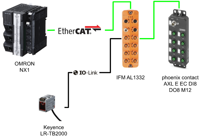
This article I will configure an EtherCAT Master on OMRON NX1, using EtherCAT IO LINK Gateway AL1332 and Phoenix Contact AL E EC DI8 DO8 M12, two EtherCAT Slaves in the EtherCAT network. for the IOLINK sensor, Keyence LR-TB2000 is used.Let’s start!
Thanks!
This article was made possible thanks to equipment loaned from OMRON Corporation and ifm efector co. ltd. Thank you very much.
Omron Japan
As a leading automation company, OMRON Corporation has developed a wide range of businesses, including control equipment centered on factory automation, electronic components, social systems such as automatic ticket gates at stations and power conditioners for solar power generation, and healthcare. , provides products and services in approximately 120 countries and regions.
Here is the website of omron:
ifm efector co. ltd.
ifm is a sensor specialist founded in Germany in 1969 with the corporate philosophy of “ifm-Close to you”. Today, They have become a large company with more than 7,000 employees in more than 95 countries around the world, and we are a globally recognized manufacturer as a pioneer of IO-Link, which is the key to IoT.

Here is the website of IFM:
Reference Link
Download ESI File
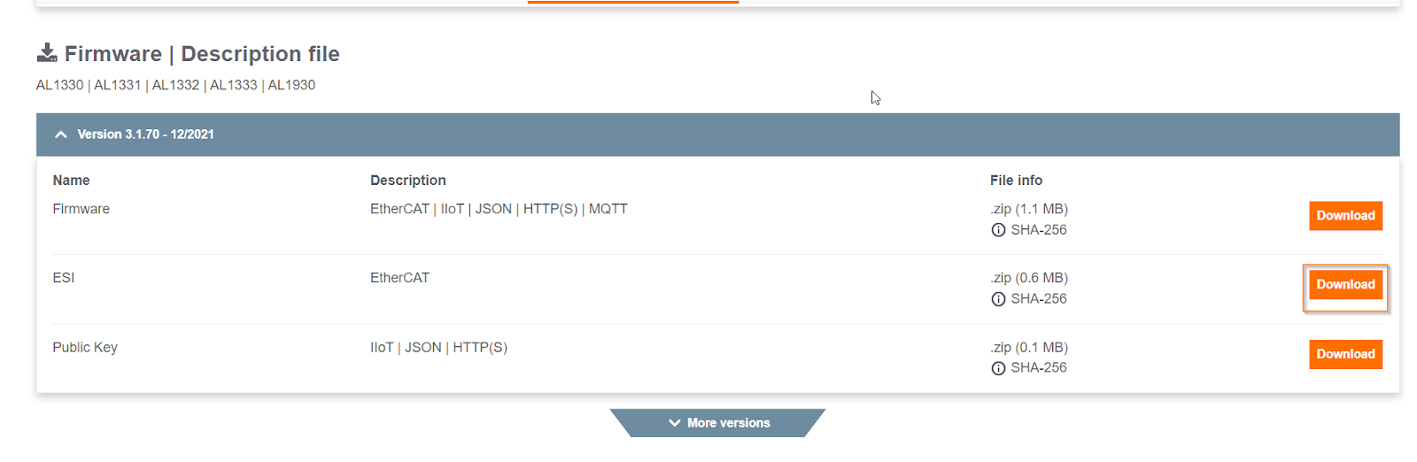
IFM AL1332
https://www.ifm.com/de/en/product/AL1332?tab=documents
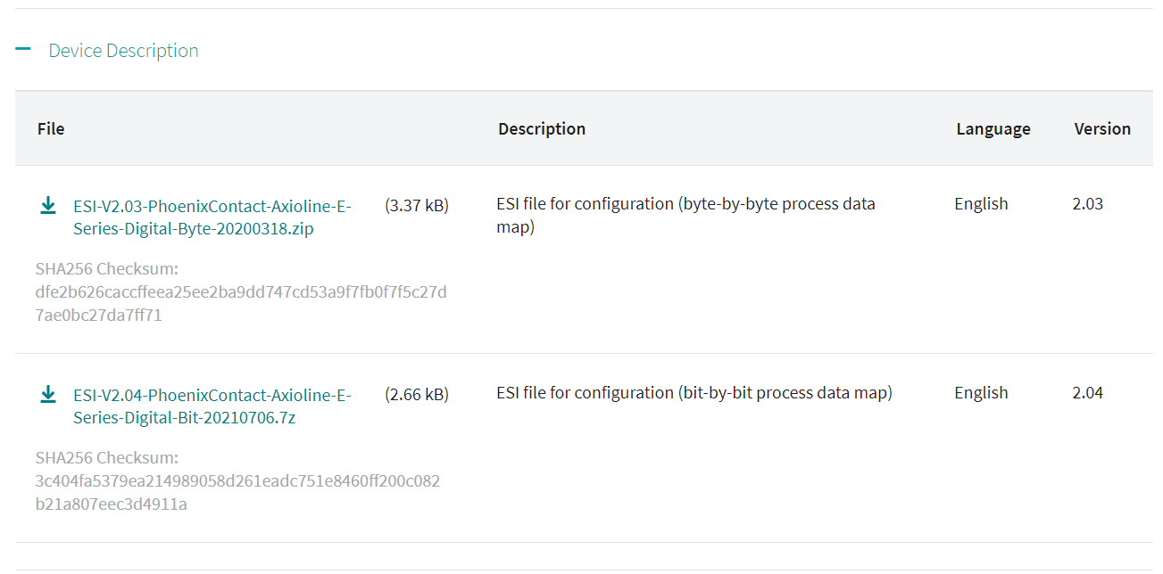
AXL E EC DI8 DO8 M12
Please access this link to download the ESI file of AXL E EC DI8 DO8 M12 – And Byte by Byte mapping is used in my tutorial.
https://www.phoenixcontact.com/ja-jp/products/io-component-axl-e-ec-di8-do8-m12-6m-2701525
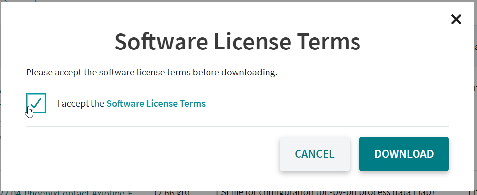
Agree the license and download the ESI File.
Implementation
Install ESI File
Open the Sysmac Studio>Configuration and Setup>Click the EtherCAT option.
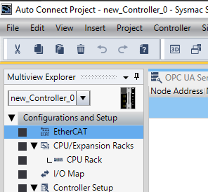
EtherCAT configuration screen is shown.Select the Master icon>Right Click>Display ESI Library.

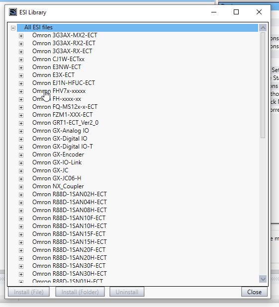
The ESI Files that are installed on your PC are shown.
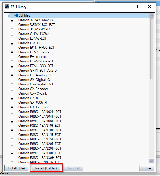
Click the Install(Folder0 button to install all ESI files that are stored in the specified folder.
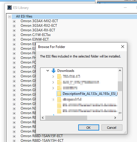
Choose your Folder and OK.
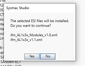
Press “Yes” to install it.
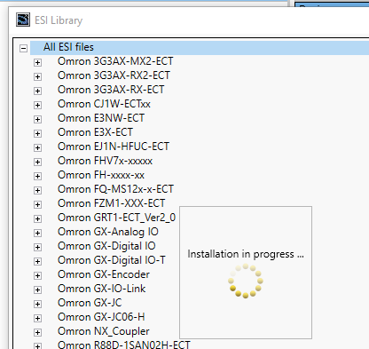
Please wait a minute..
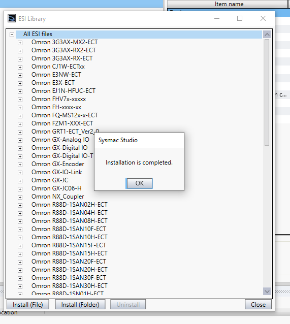
Done!
Insert Slave
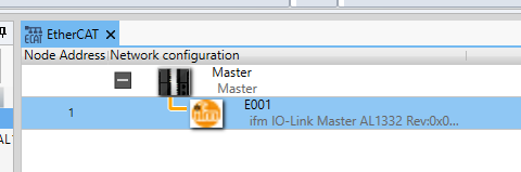
Now we can install the Slave in our EtherCAT Network.Go to the Tool box and select the IO-Link master AL1332>Right>Insert it.
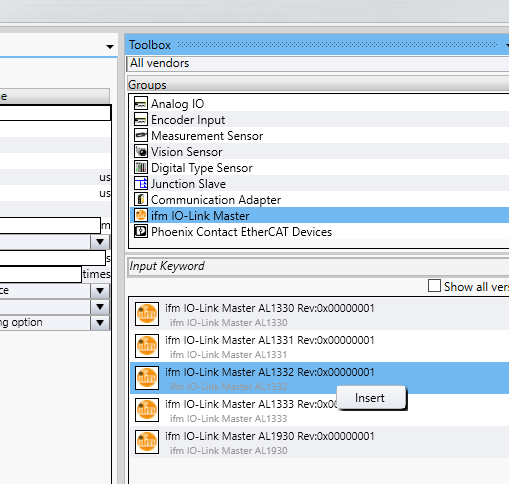
In your Ethercat Network, IFM IO Link Ethercat Master AL1332 is inserted.
Do the same operation for the AXL E EC DI8 DO8 M12 6P IP67 Ethercat IO Block module in your Ethercat network.

Write Slave Address
Connect your PC with NX CPU.
Choose the NX CPU>Right Click>Write Slave Node Address.

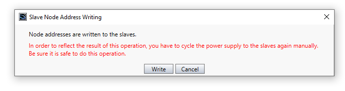
You can see the Present value of each Ethercat slave’s node address – Enter the new value in the “Set Value” File and press “Write”Button to write the Node address to the slave.

Press “Write” Button to confirm the operation and reset your power.
Configure Slave
Because IFM AL1332 is the Ethercat IO LINK Master, we can configure each port as “Digital Input/Digital Output/IOLINK/Not used.
Choose AL132 and go to the Module Configuration>click the “Edit Module Configuration”.

All port settings are shown here.
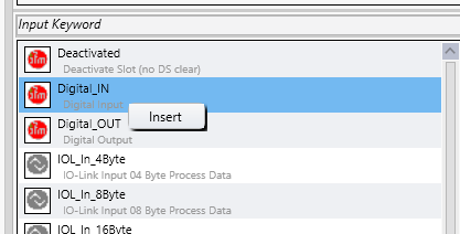
Select Digital_IN from the Toolbox>Right Click>Insert.
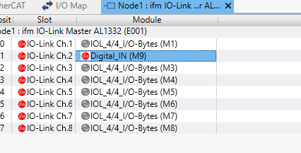
The configuration of CH2 is modified to Digital input now.
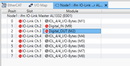
Let’s do the same operation for the CH2 as Digital Output.
Download
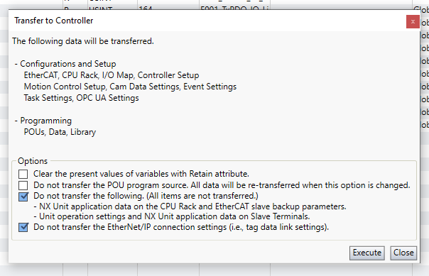
Download your project to CPU.
Press Execute to confirm the operation.
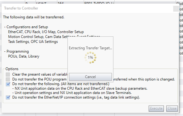
Please wait a minute..
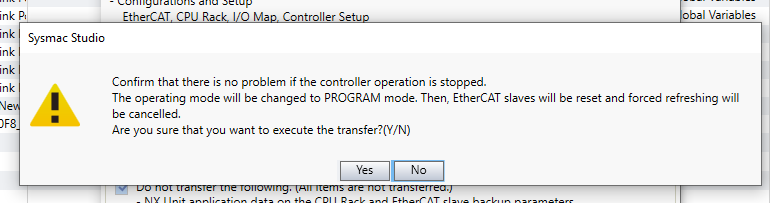
Press Yes to transfer the project.
Please wait mins..

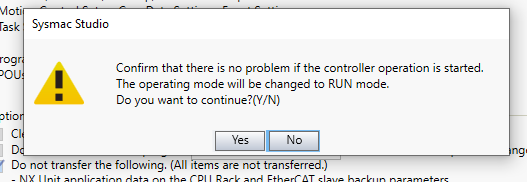
Press Yes to change your CPU to run mode.
Done!

Check Connection Status
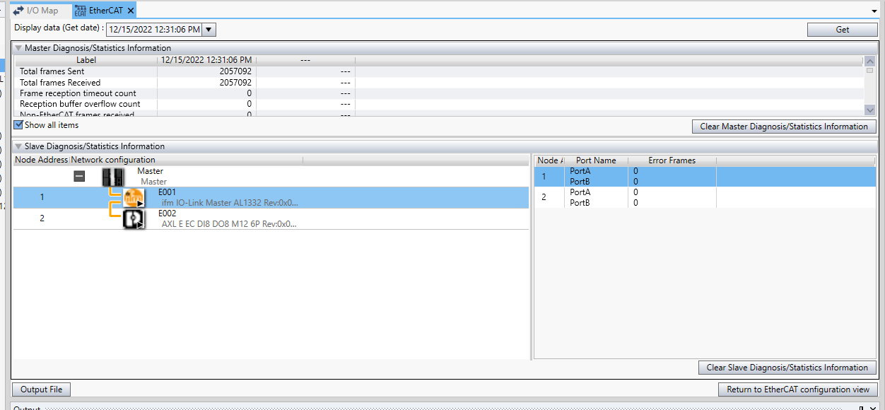
Right Click your Ethercat Master>Display Diagnosis/Statistics Information to check the connection status.

The status of your Master and all slaves are displayed.
Get Wireshark data
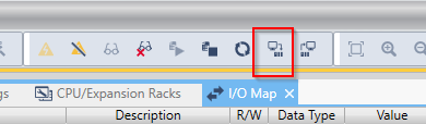
And also we can get the Wireshark data from our tools.Right click the Master>Select the Display Packet Monitor option.

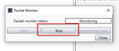
Press “Start” Button to start the package capture.

Press “Stop” to end your capture.
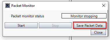
Finally you can press the “Save Packet Data” Button to save your Packet Data.
Select the saving Path.
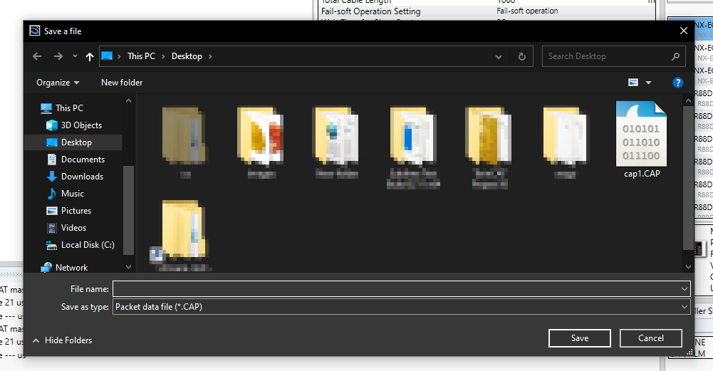
A .CAP File is stored in your PC and it can open with Wireshark.


Mapping
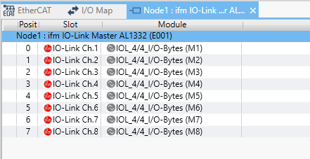
Then we need to configure the IO mapping for each Ethercat Slave. Go to Configurations and Setup>I/O Map to open the Mapping Tool.

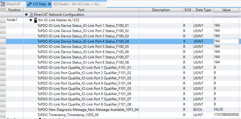
As you see, for Node1 we have IFM AL1332, for Node2 we have AXL E EC DI8 DO8.
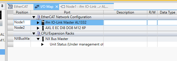
For example,We can confirm the connection status of each port.
AXL E EC DI8 DO8 M12
There is a great function in omron to save your life – It is “Create Device Variable”. Right Click the AXL E EC DI8 DO8 M12>Create Device Variable to automatically create the variables.

Done!

AL1332
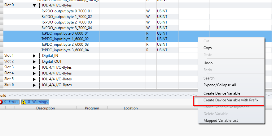
Do the same Operation with AL1332 – and I use the Prefix function also this time.All the variables are created from this function, there is a default header.
For example, if I configure the Prefix as “MyDevices”, all the variables that are created here will start with a “MyDevices” Header.
Program
Add Function Block
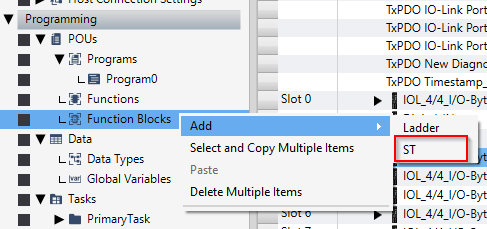
Now we can create a Function Block to get the Qualifier and status of the AL1332 modules.
Go to Programming>POUS>Function Block>Right Click>Add>ST.
Function Block is created and please change it to a meaningful name.
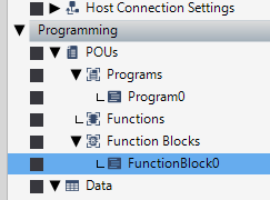
FB_IFM_AL1322_Qualifier
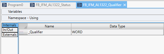
Here is the Function Block to get the AL1332 status from the Qualifier variable.
Internals
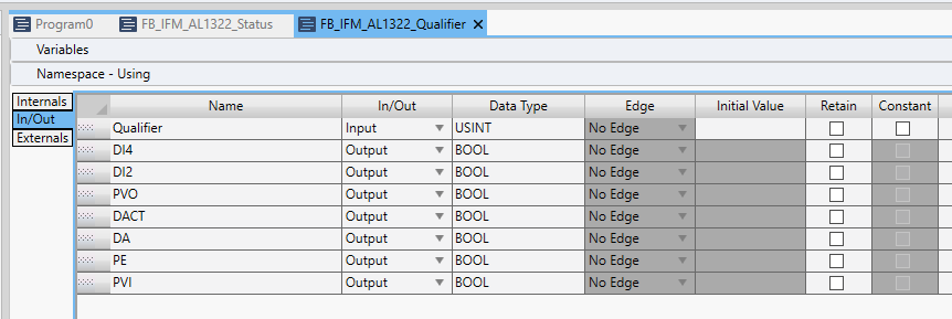
In/Out
Configure “Qualifier” as the Input parameter of your function block, and configure all status as Bool output.
Program
Here is the Program.
| _Qualifier:=USINT_TO_WORD(Qualifier); DI4:=(_Qualifier & WORD#2#0000_0001)<>0; DI2:=(_Qualifier & WORD#2#0000_0010)<>0; PVO:=(_Qualifier & WORD#2#000_0100)<>0; DACT:=(_Qualifier & WORD#2#0001_0000)<>0; DA:=(_Qualifier & WORD#2#0010_0000)<>0; PE:=(_Qualifier & WORD#2#0100_0000)<>0; PVI:=(_Qualifier & WORD#2#1000_0000)<>0; |
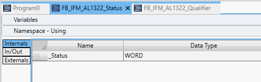
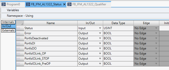
FB_IFM_AL1322_Status
Here is the Function Block to get the AL1332 status from the Status variable.
Internals
In/Out
Configure “Status” as the Input parameter of your function block, and configure all status as Bool output.
Program
Here is the program.
| //Error _Status:=USINT_to_WORD(Status); Error:=(_Status & WORD#2#1111_0000)<>0; //Port _Status:=_Status& WORD#2#0000_1111 ; PortIsDeactivated:=_Status = WORD#16#0; PortIsDI:=_Status=WORD#16#1; PortIsDO:=_Status = WORD#16#2; PortIsIOLink_OP:=_Status = WORD#16#3; PortIsIOLink_STOP:=_Status=WORD#16#4; PortIsIOLink_PreOP:=_Status=WORD#16#5; |
Main
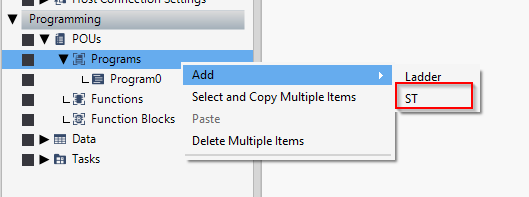
Go to Programming>Add>ST to insert a new ST program.
Internals
Define the Function Block instance that we created in the previous step and a refresh timer.

Externals
Externals is the field to link all the variables outside the POUS.

Program
Here is the program and we will get the Qualifier and Status from Port1/2/3, and The output will be set to 1 of our Phoenix Contact module , if IN2 is equal to true.
Finally we can get the data of Keyence IOLINK Sensor if the IO Link Status of Port 1 is OK.
| //Qualifier AL1322_Qualifier[1]( Qualifier:=E001_TxPDO_IO_Link_Port_Qualifie_IO_Link_Port_1_Qualifier_F101_01 ); AL1322_Qualifier[2]( Qualifier:=E001_TxPDO_IO_Link_Port_Qualifie_IO_Link_Port_2_Qualifier_F101_02 ); AL1322_Qualifier[3]( Qualifier:=E001_TxPDO_IO_Link_Port_Qualifie_IO_Link_Port_3_Qualifier_F101_03 ); //Status AL1322_Status[1]( Status:=E001_TxPDO_IO_Link_Device_Status_IO_Link_Port_1_Status_F100_01 ); AL1322_Status[2]( Status:=E001_TxPDO_IO_Link_Device_Status_IO_Link_Port_2_Status_F100_02 ); AL1322_Status[3]( Status:=E001_TxPDO_IO_Link_Device_Status_IO_Link_Port_3_Status_F100_03 ); IF myStep=0 AND AL1322_Qualifier[2].DI2 THEN MyTimer1(IN:=TRUE,pt:=T#1s); if MyTimer1.Q THEN myStep:=1; MyTimer1(IN:=False); END_IF; END_IF; if AL1322_Qualifier[2].DI2 = false THEN myStep:=0; END_IF; CASE myStep OF 0: E002_RxPDO_Mapping_Digital_Outpu_Digital_Output_Bits_0_7_5000_01:=16#00; ifm_al1332_Slot2_DORxPDO_output_byte_0_7000_01:=0; 1: MyTimer1(In:=True, PT:=T#1s); E002_RxPDO_Mapping_Digital_Outpu_Digital_Output_Bits_0_7_5000_01:=16#FF; ifm_al1332_Slot2_DORxPDO_output_byte_0_7000_01:=1; IF MyTimer1.Q THEN myStep:=2; MyTimer1(In:=FALSE); END_IF; 2: MyTimer1(In:=True, PT:=T#1s); E002_RxPDO_Mapping_Digital_Outpu_Digital_Output_Bits_0_7_5000_01:=16#00; ifm_al1332_Slot2_DORxPDO_output_byte_0_7000_01:=0; IF MyTimer1.Q THEN myStep:=1; MyTimer1(In:=FALSE); END_IF; END_CASE; Distance:=0; if AL1322_Status[1].PortIsIOLink_OP THEN ShiftWord1:= SHL( USINT_TO_WORD(ifm_al1332_Slot0_IolinkdataTxPDO_input_byte_0_6000_01) ,8 ); ShiftWord2:=USINT_TO_WORD(ifm_al1332_Slot0_IolinkdataTxPDO_input_byte_1_6000_02); Distance:=WORD_TO_INT(ShiftWord1 or ShiftWord2); END_IF; |
Register in variable Table
As we mentioned before, Externals is a field for us to connect the variables outside our POUs.Right click the variable that you would like to connect>Register in variable table.
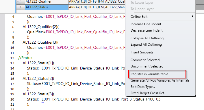
Choose External Variable.

All the External variables are linked.

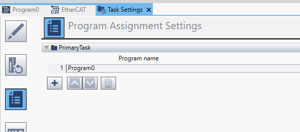
Task Settings
Because a new POU is created and we need to configure it in the Task setting. Go to the Task Setting object.

Click the “+” Button to insert the ST program that we created before.
Result
IF OK
https://youtube.com/shorts/3rqPUhrc2Tw
IF Error
https://youtube.com/shorts/cipnFSlthX8
Operation
Source Code
https://github.com/soup01Threes/OMRON/blob/main/Ethercat_Demo_IFM_PhoenixContact_Slave.smc2