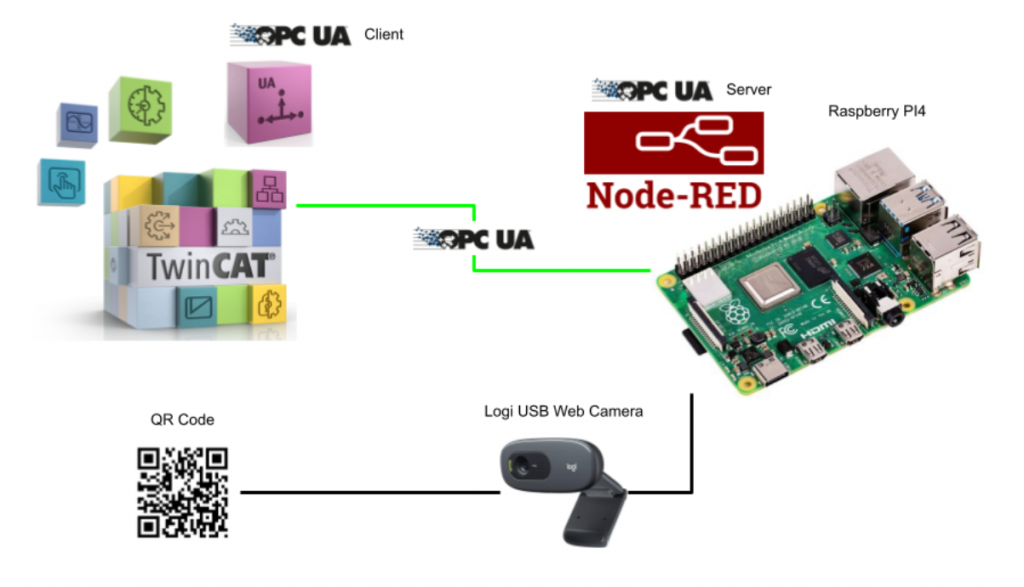
In this article, Node Red is installed on PI4, the QR Code is recognised by the USB camera, the OPC UA Server is started at the same time, and accessed and linked from TwinCAT3 TF6100. Because the OPC UA Client which can be tried free and easily at present is probably only TwinCAT3.
Let’s get started.
Camera
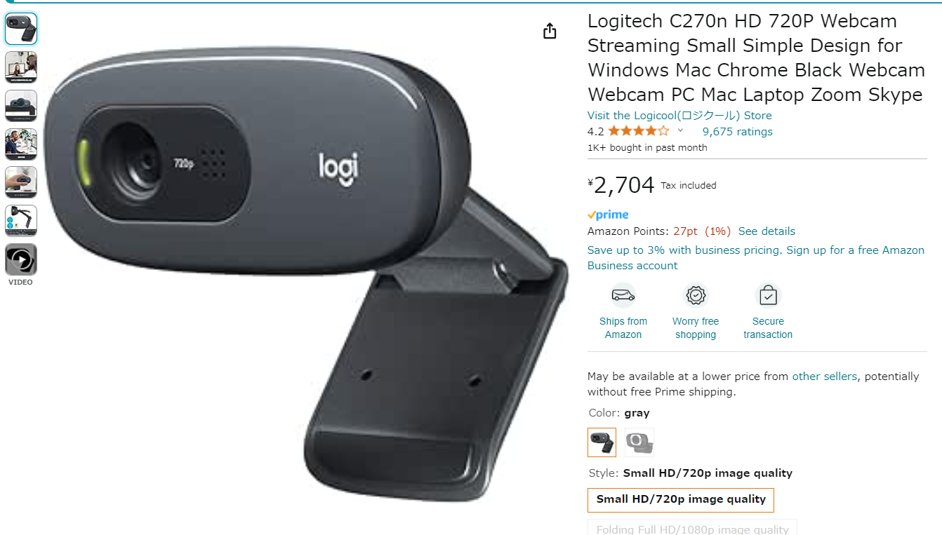
This is Logi’s ¥2500 Web Camera that will be used in this project.
Configuration
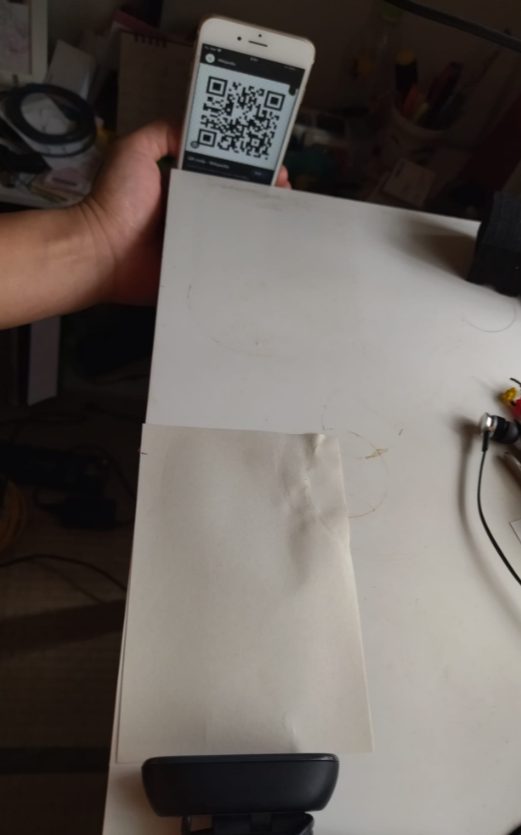
Here is my hand-made QR Code Reading operation.
Implementation
Operation Flow
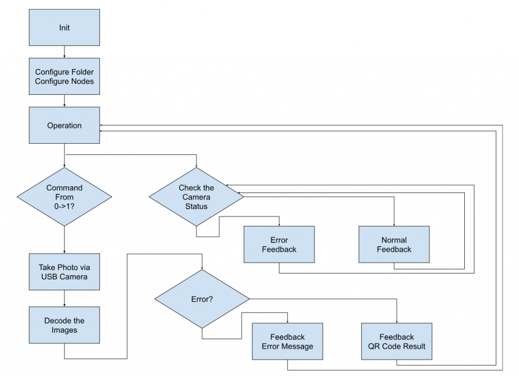
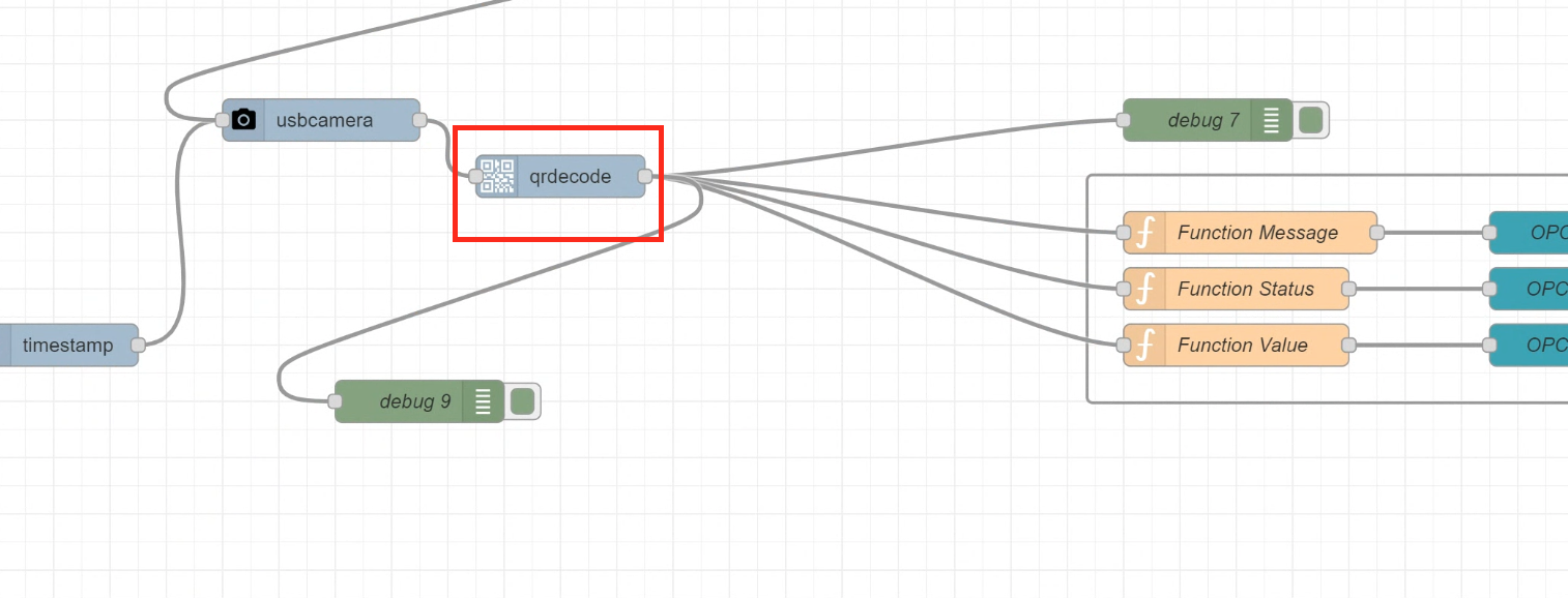
This is the Control Flow for this article.
Raspberry PI Side
The first step is to build from the Raspberry PI side.
Check Camera
Check that the camera has been recognised.
lsusb
Use the lsusb command to list the USB devices currently recognised by the Raspberry PI.
| pi4@raspberrypi:~ $ lsusb Bus 002 Device 001: ID 1d6b:0003 Linux Foundation 3.0 root hub Bus 001 Device 003: ID 046d:0825 Logitech, Inc. Webcam C270 Bus 001 Device 002: ID 2109:3431 VIA Labs, Inc. Hub Bus 001 Device 001: ID 1d6b:0002 Linux Foundation 2.0 root hub |
https://www.baeldung.com/linux/check-for-usb-devices
grep
Next, use the grep command to extract only the Webcam C270 (the webcam used in this article) from the output from lsusb.
| pi4@raspberrypi:~ $ lsusb | grep ‘Webcam C270’ Bus 001 Device 003: ID 046d:0825 Logitech, Inc. Webcam C270 |
https://phoenixnap.com/kb/grep-command-linux-unix-examples
Install Node-Red
Next, refer to the following article to install Node-RED on a Raspberry PI4.
Node-Red Side
Now we need to program Node-Red.
Install Node
The first section we will describe the Node used in this article.
node-red-contrib-opcua
This is a Node that implements OPC UA functionality.
https://flows.nodered.org/node/node-red-contrib-opcua
Install node-red-contrib-opcua with the following command.
| npm install node-red-contrib-opcua |
Once the installation of node-red-contrib-opcua is complete, the OPC UA Node will appear.
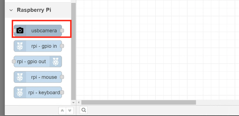
node-red-contrib-usb-camera
This is a Node that implements the operation of a USB camera.
https://flows.nodered.org/node/@prescient-devices/node-red-contrib-usb-camera
下記のコマンドでnode-red-contrib-usb-cameraをインストールします。
| npm install @prescient–devices/node–red–contrib–usb–camera |
Once the installation of node-red-contrib-usb-camera is complete, the usbcamera Node is displayed.
node-red-contrib-qrdecode
This is a Node that implements a QR Code decode.
https://flows.nodered.org/node/node-red-contrib-qrdecode
Install node-red-contrib-qrdecode with the following command.
| npm install node-red-contrib-qrdecode |
Once the installation of node-red-contrib-qrdecode is complete, the qrcode Node will appear.
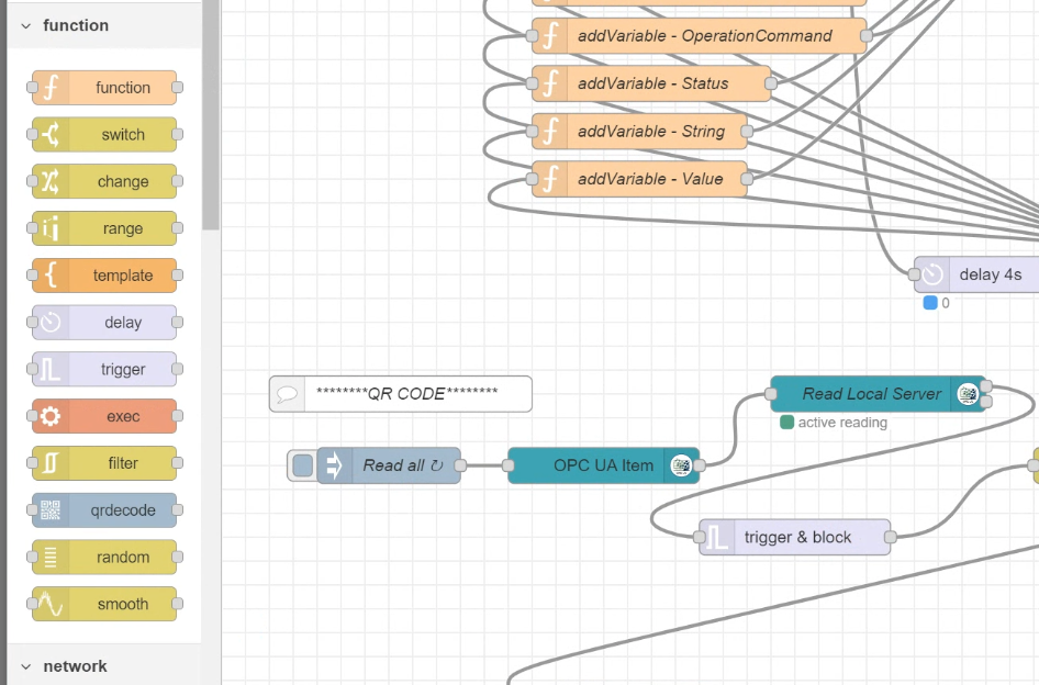
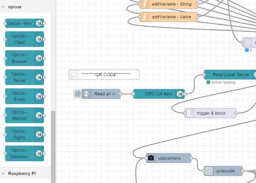
Flow
Here is an explanation of Flow creation.
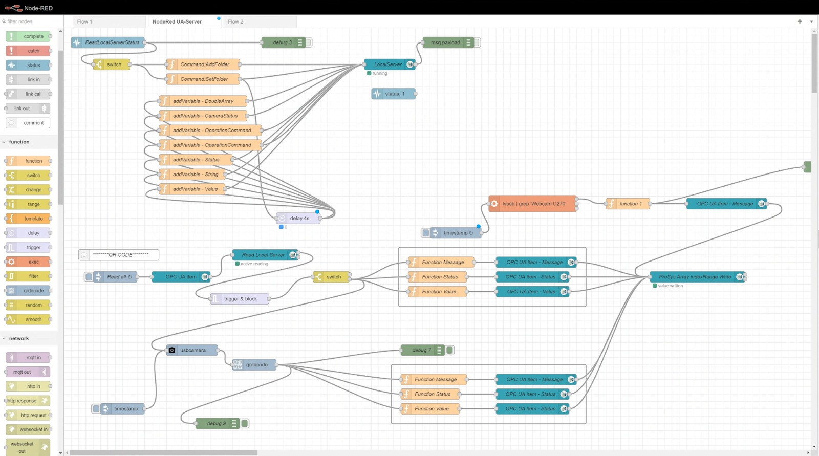
Configure OPC-UA Server
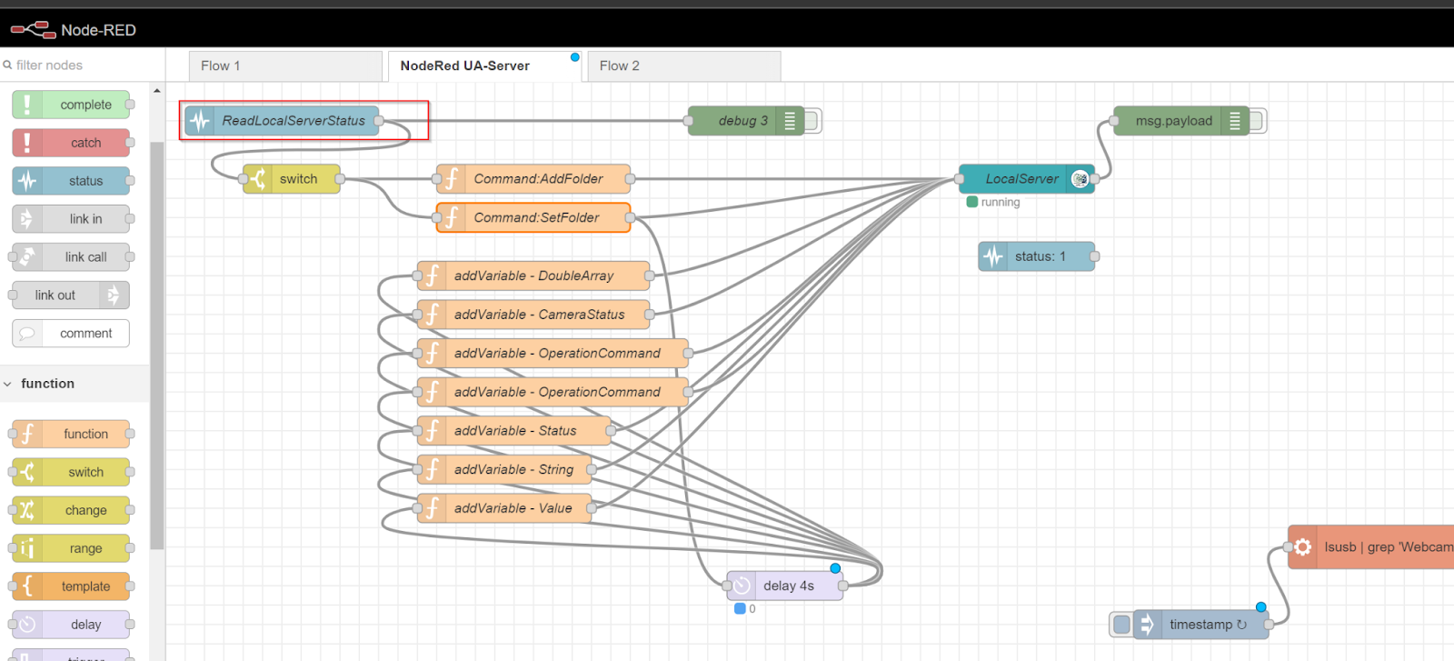
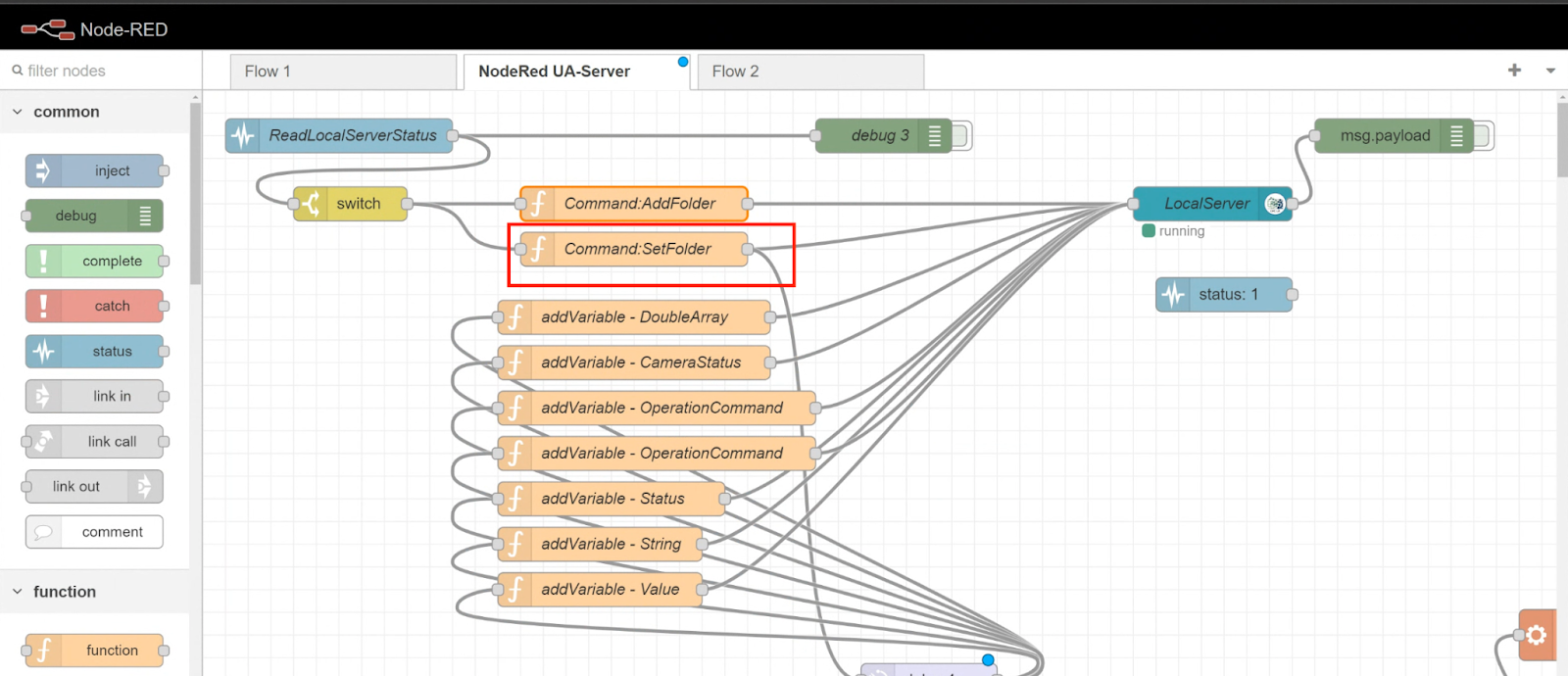
This is a Flow to launch the OPC UA Server from Node-Red.
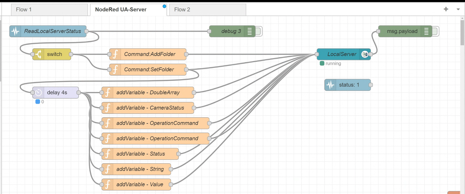
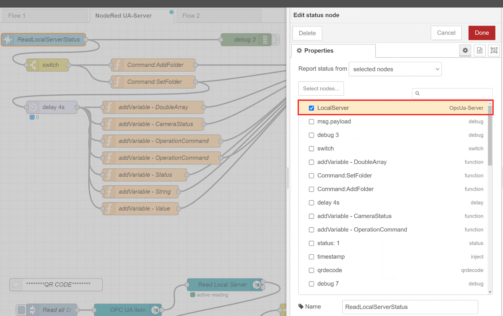
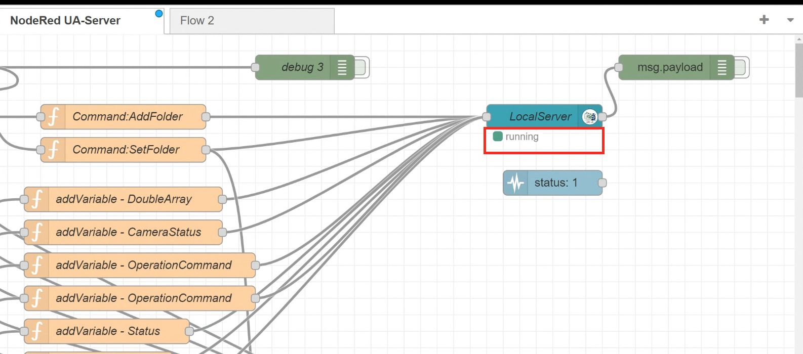
Read OPC UA Server Running Status
First use the Status Node to Check whether the OPC UA Server has started up.
Status Node allows you to get the status of Nodes in the same Flow Tab, so this time you will check the status of the Local Server in Node-Red.
Check the OPC UA Server Status
Having obtained the Local Server from the Status Node earlier, the next step is to use the switch Node to control the conditional decision.
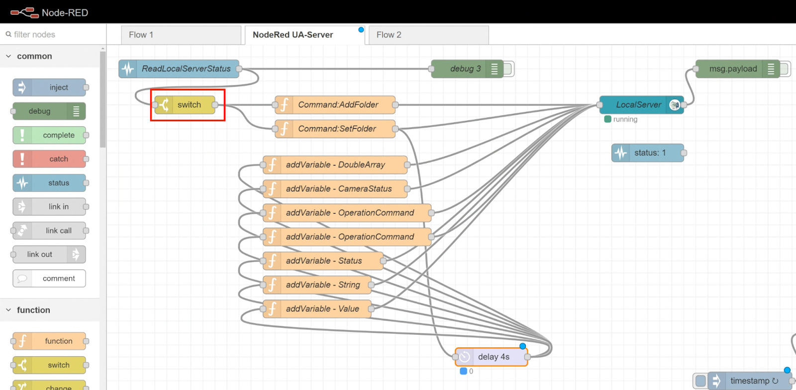
Only “running” statuses from the Payload of the current Status Node can proceed to the next Node.
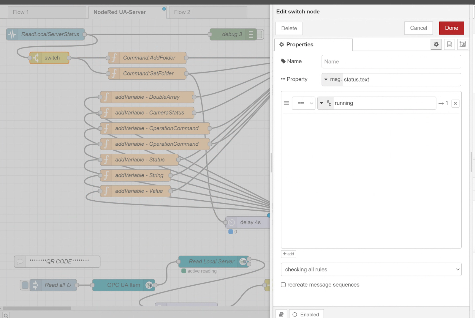
The “running” is the indication from Node-Red that the OPC UA Server is “running” after a successful start-up.
Configure Server Folder/Nodes
If you can confirm that the OPC UA Server has started up, the next step is to add Folders and Nodes to the OPC UA Server.
Add Folder inside OPC UA Server
First add a Folder to the OPC UA Server; by adding Folders, you can separately catalog Nodes with different purposes.
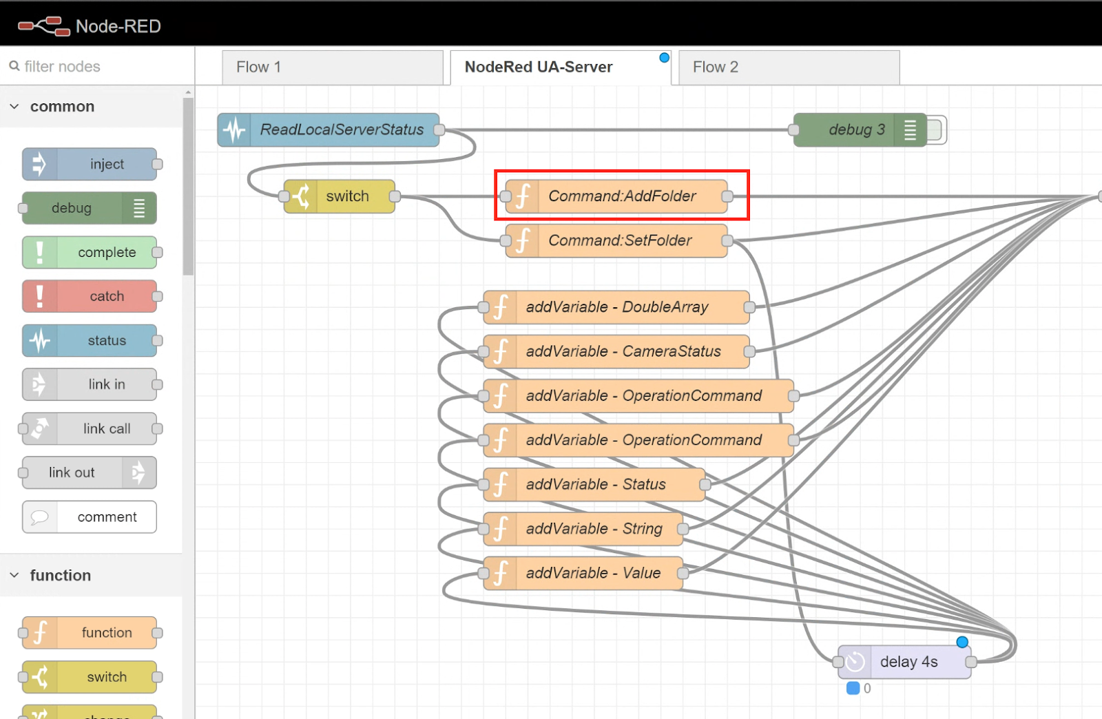
Topic is the Folder detail and payload is the command used to add the Folder.
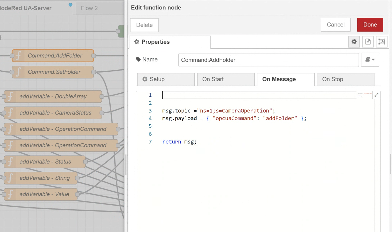
| msg.topic =”ns=1;s=CameraOperation”; msg.payload = { “opcuaCommand”: “addFolder” }; return msg; |
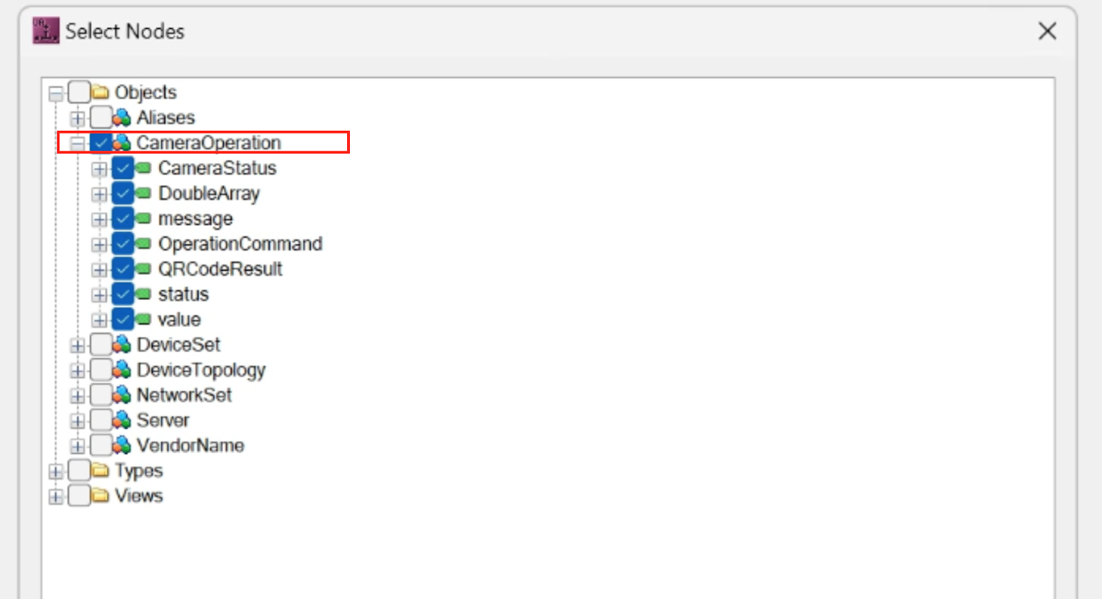
After executing the previous command, when accessing the OPC UA Server using uaExpert or TwinCAT3 TF6100, a Folder called “CameraOperation” is created.
Set the Folder
You want to create the new Node under the Folder that has just been added, so use the Set Folder command.
Topic is the details of the Folder you are about to work with and payload is the command used to set the Set Folder.
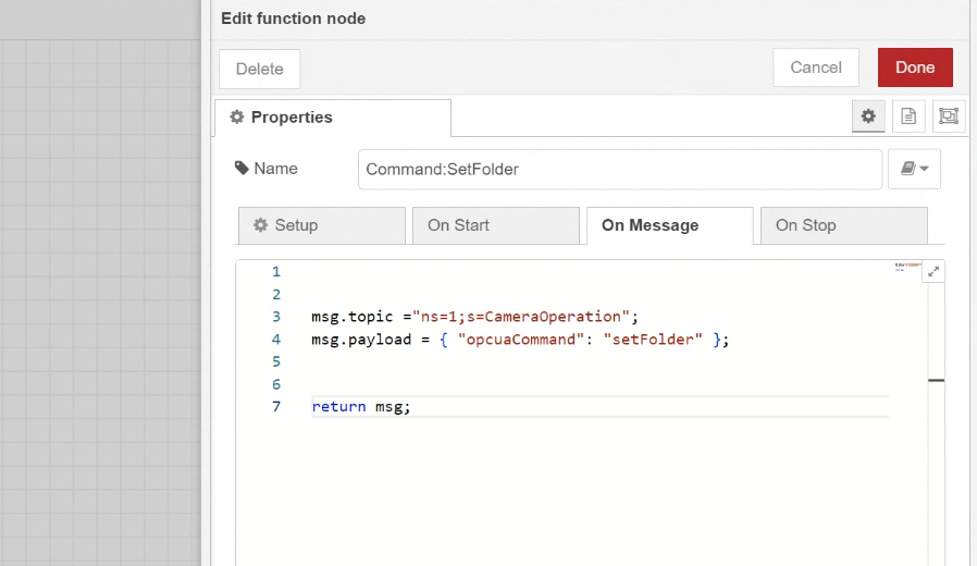
| msg.topic =”ns=1;s=CameraOperation”; msg.payload = { “opcuaCommand”: “setFolder” }; return msg; |
Connect the OPC UA Server Node
Next, if you connect the Folder Operation Node to the OPC UA Server Node, the OPC UA Server will automatically create a CameraOperation Folder and also set the Folder you are about to work with to CameraOperation.
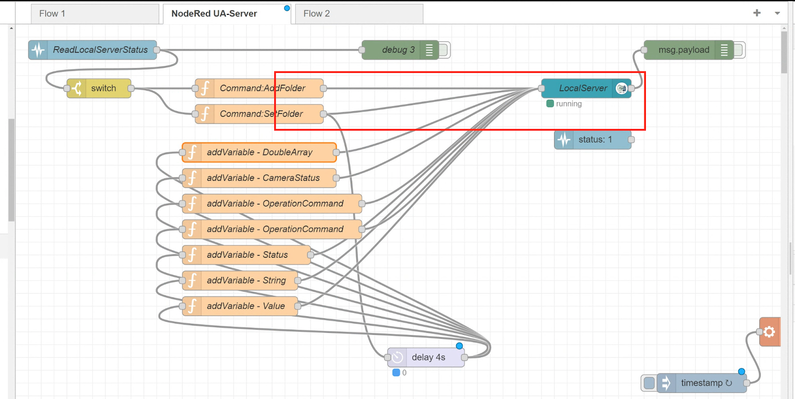
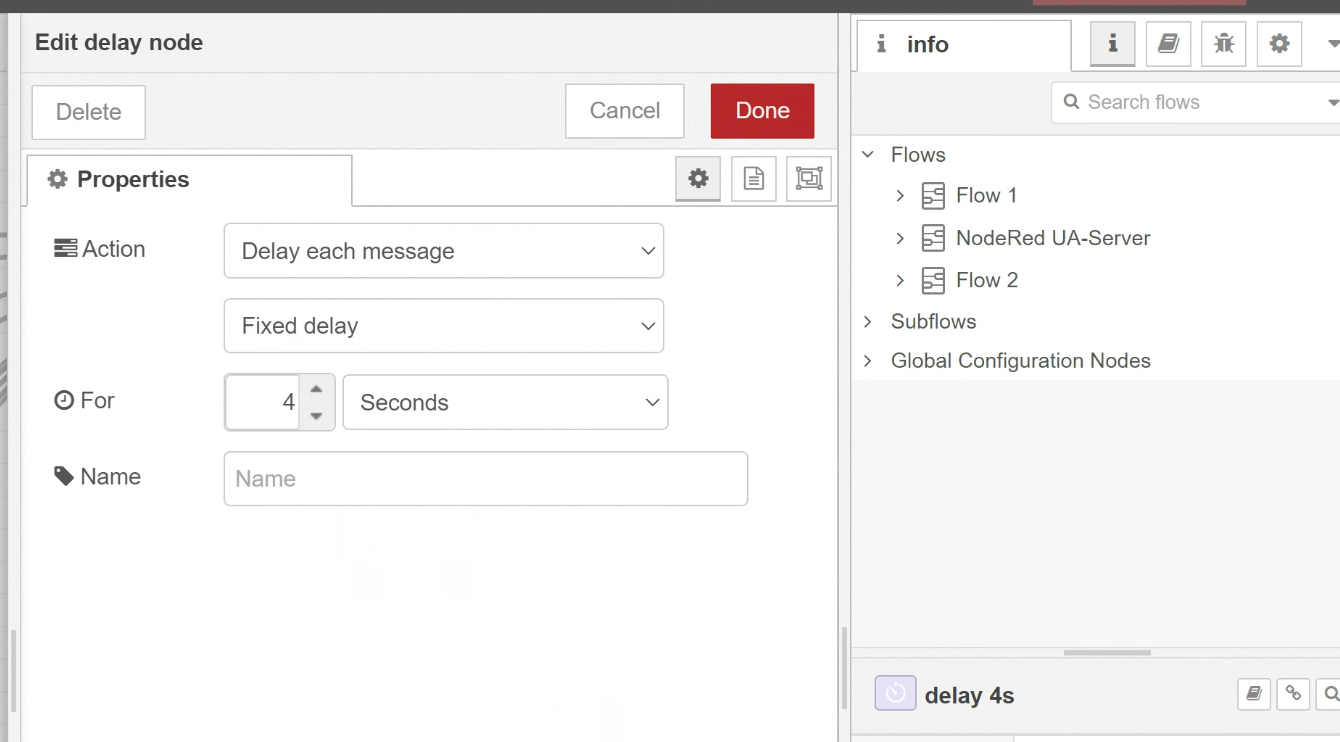
Process Delay
Set Delay until Set Folder is available.
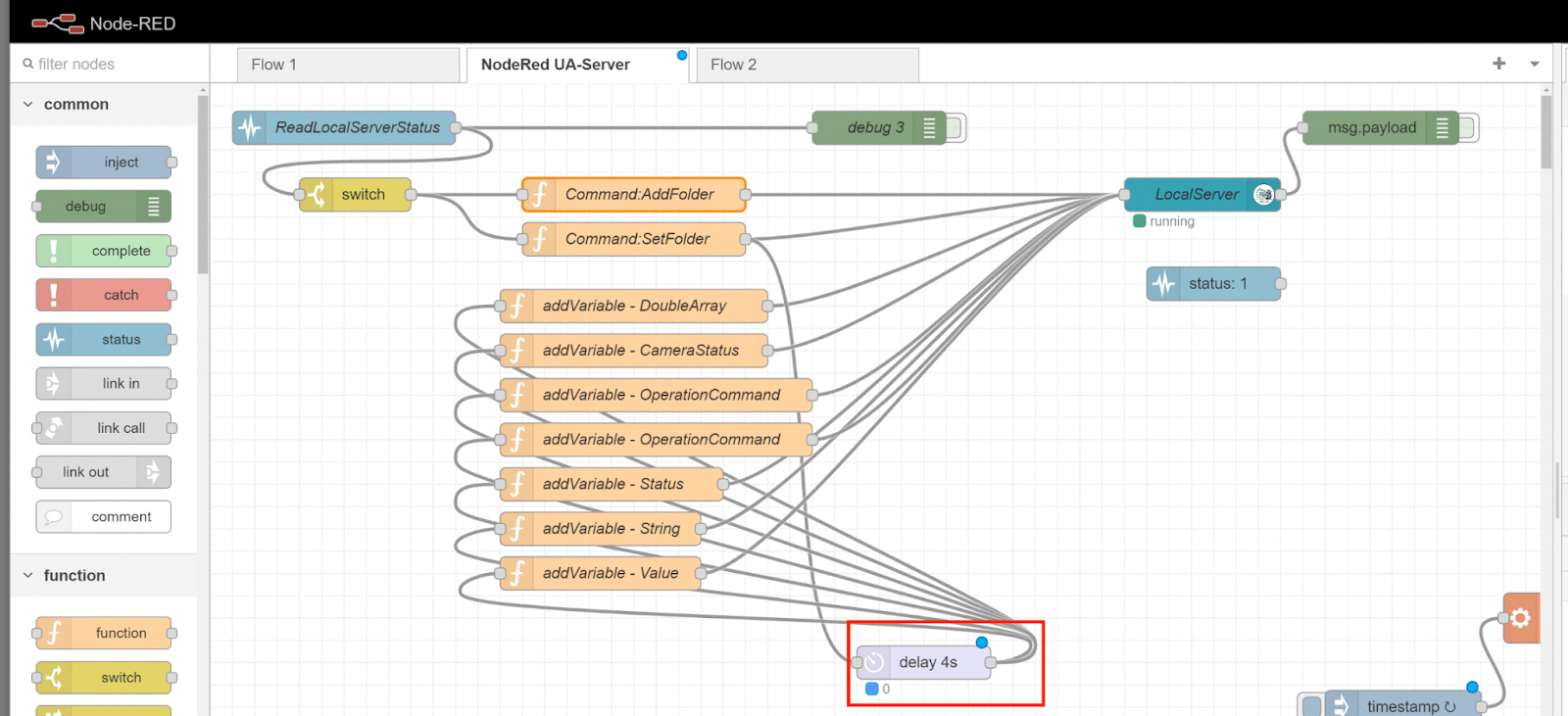
In Node-RED, the Node of delay can be used to delay operation.
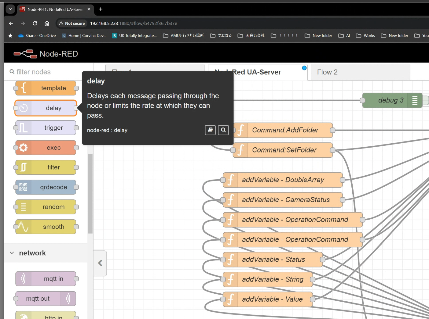
This time set to fixed 4s Delay.
Add Variables into OPC UA Server
The next step is to add variables to the OPC UA Server.
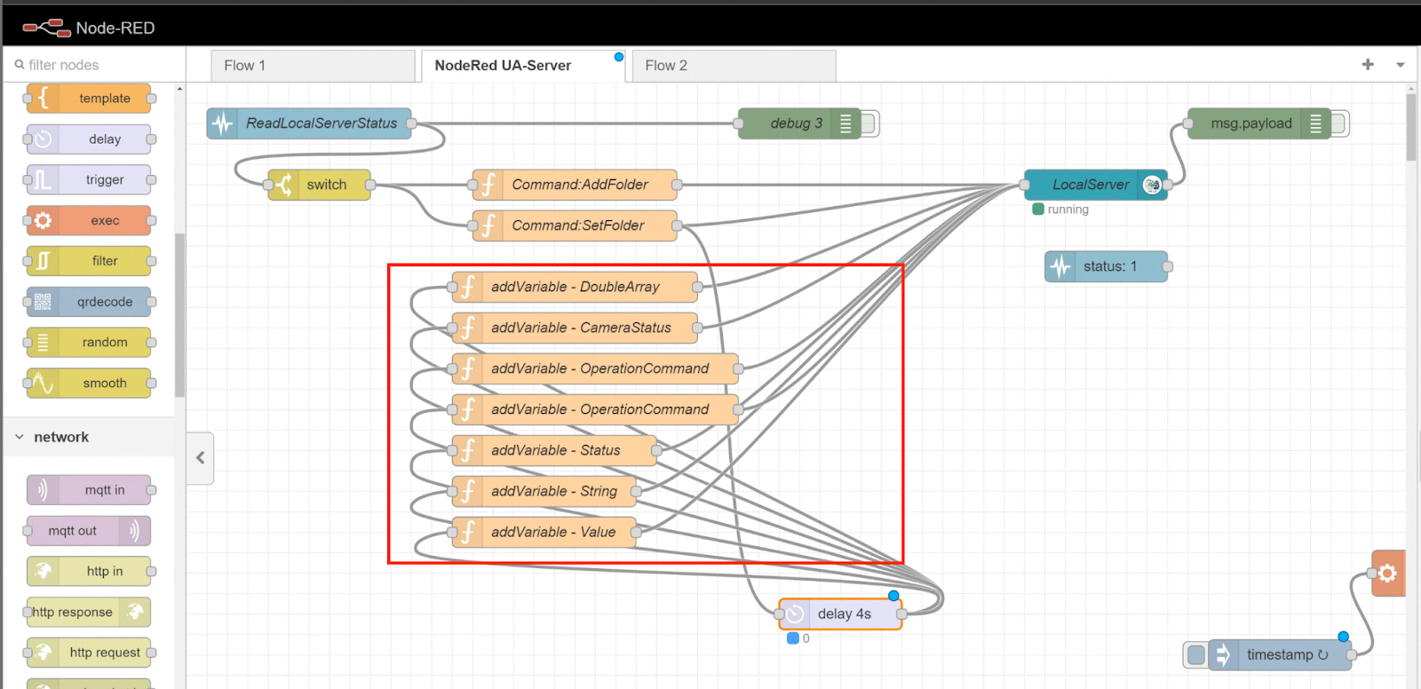
Basically, you enter the details of the variable you want to add in the topic and set the addVariable command in the payload.
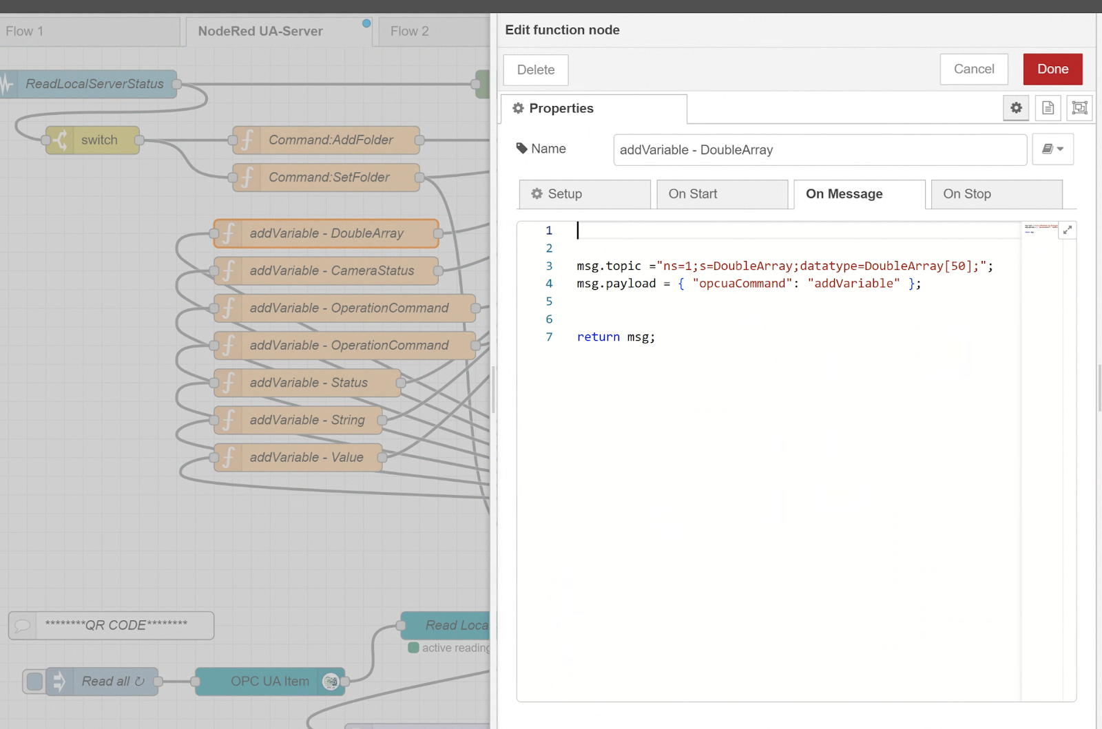
The other Node variables are not explained in detail, as it is just the same operation.
| msg.topic =”ns=1;s=DoubleArray;datatype=DoubleArray[50];”; msg.payload = { “opcuaCommand”: “addVariable” }; return msg; |
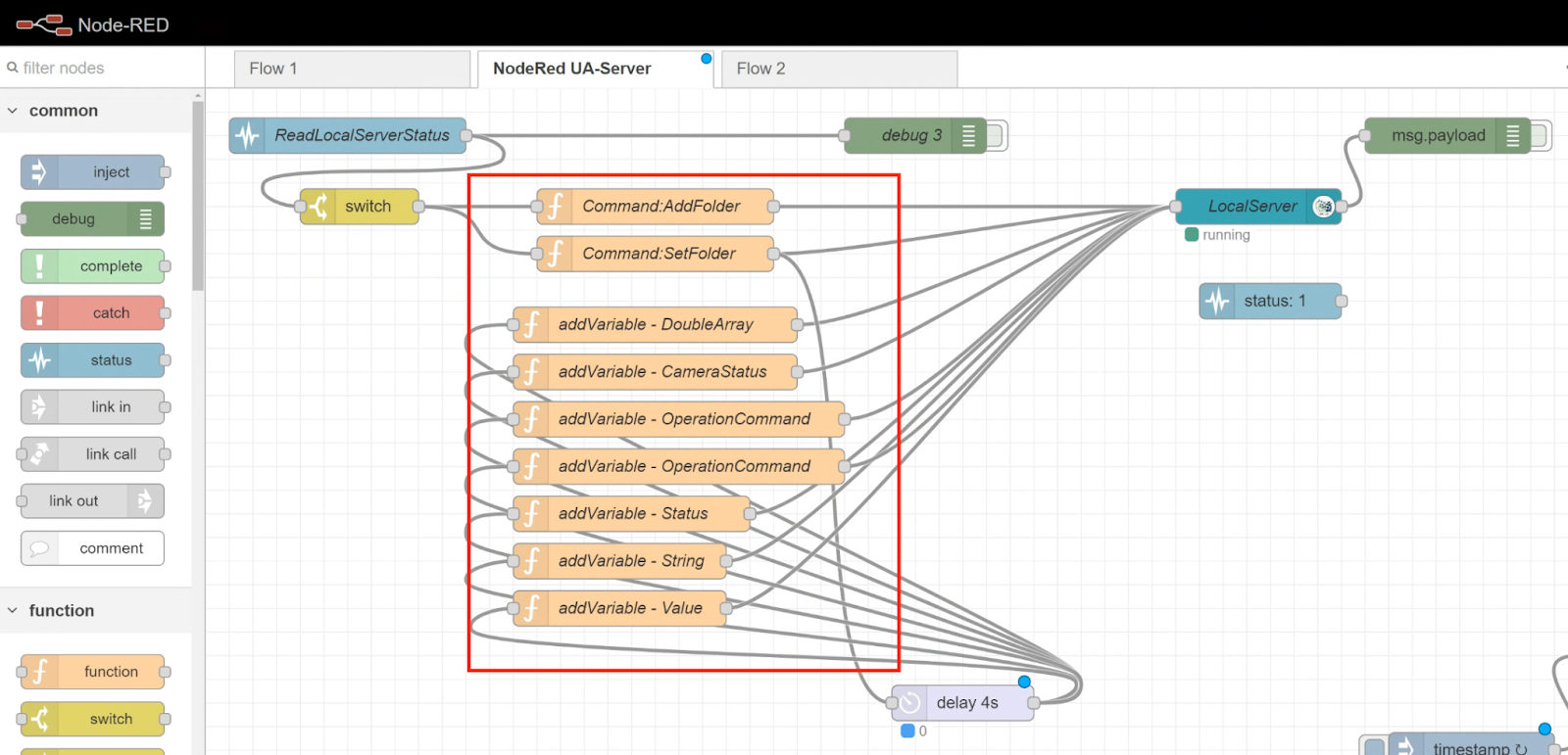
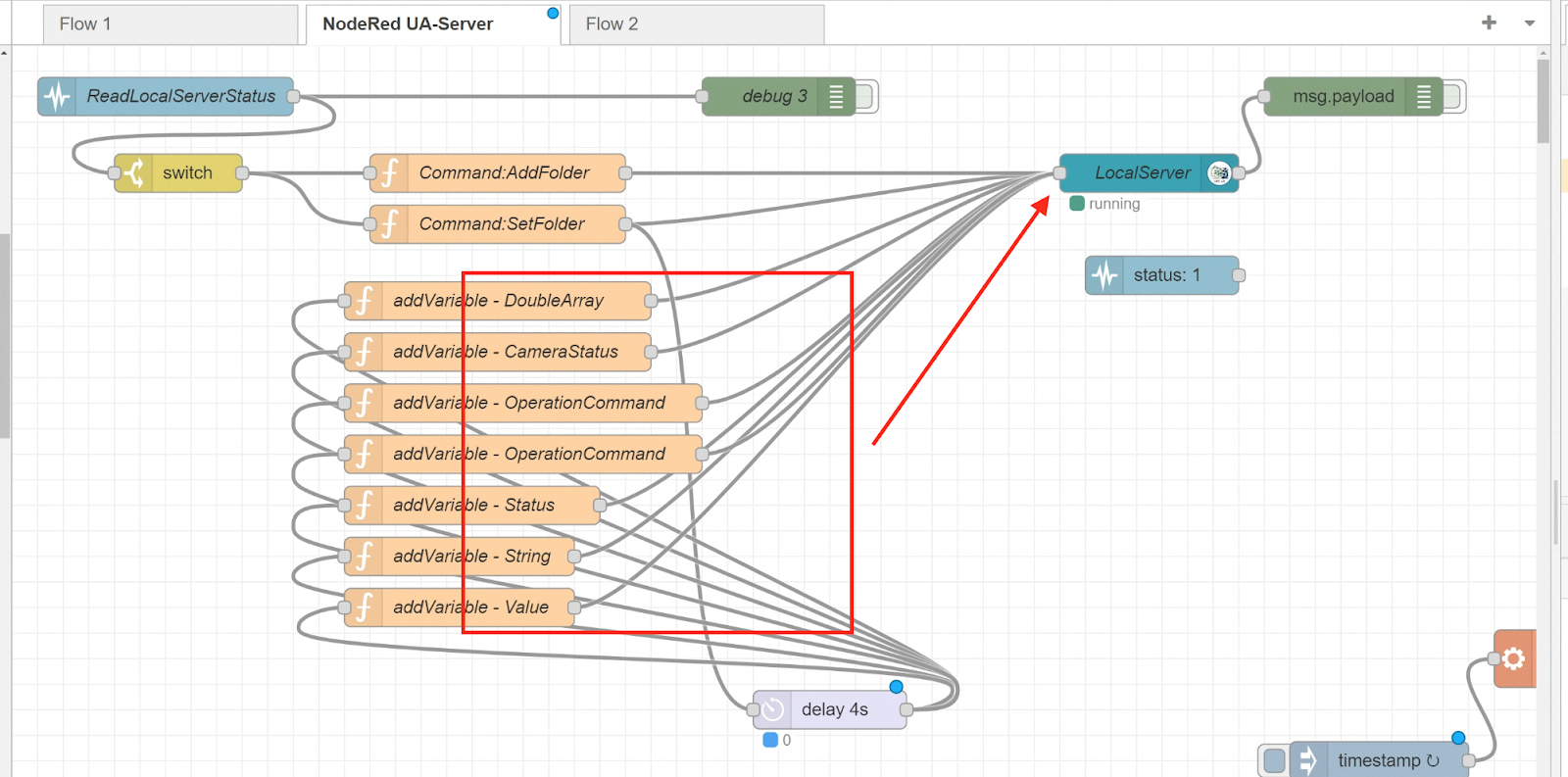
Connect all Variables to OPC UA Server
After building all the necessary Node variables for the application, connect with the Local Server and let the OPC UA Server create the Node variables.
We finished the configuration of OPC UA server.
Configure USB Camera
The following section describes the Flow until the USB camera operates and decodes the QR Code.
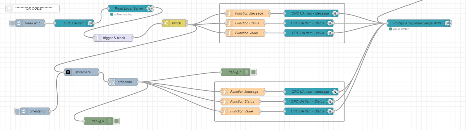
Read Trigger Command via OPC UA
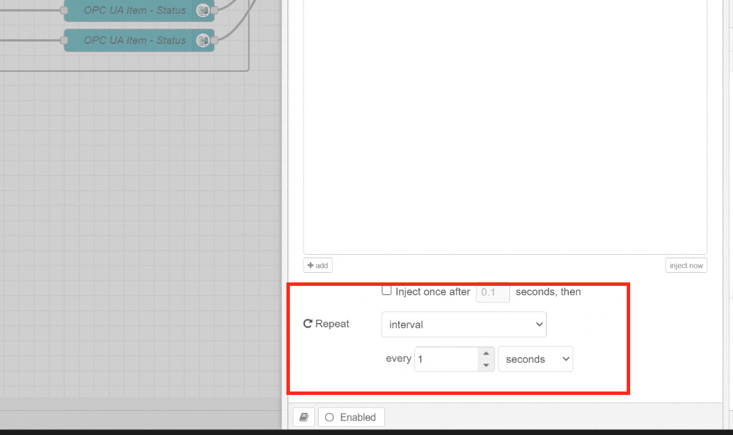
Reads commands from the OPC UA Client in cycles.
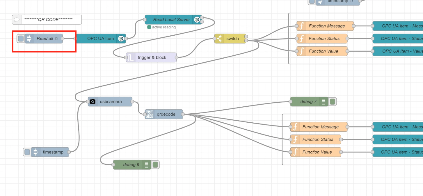
From the Inject Node, detailed settings such as the time of repeat execution can be configured.
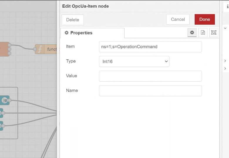
Configure the reading Node
The next step is to set up the Camera command that you want to read on the Local OPC UA Server.
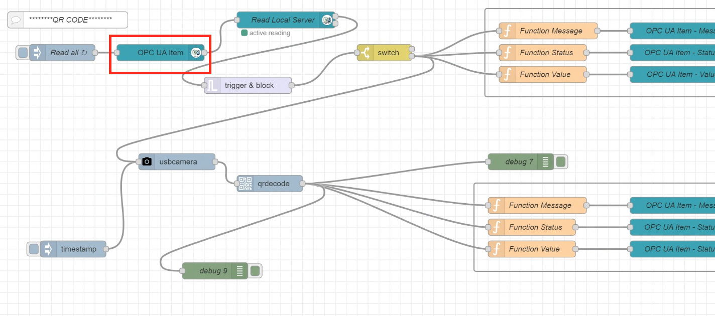
And we will Monitor the OperationCommand.
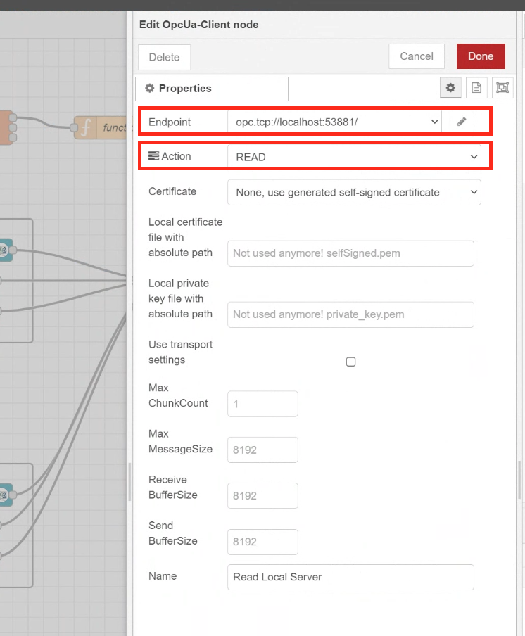
Set up the OPC UA Server Connection
Add a Local OPC UA Client to access the OPC UA Server node.
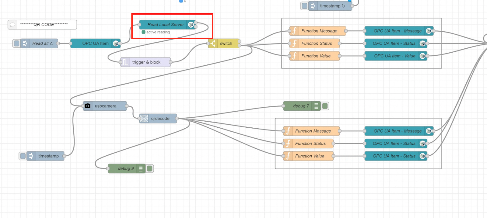
The Endpoint is localhost and the Action is set to READ.
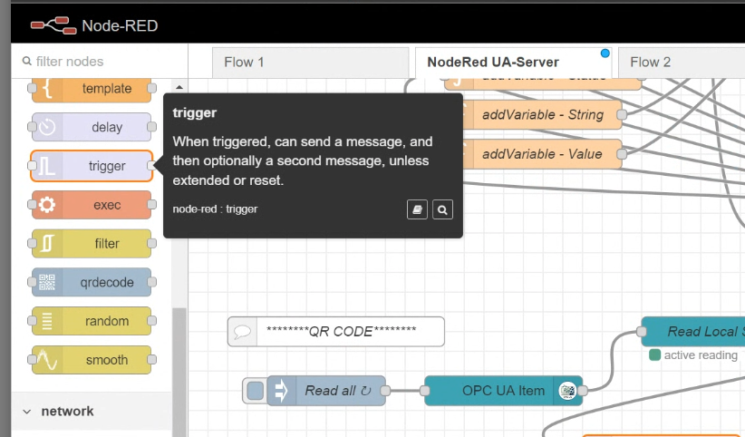
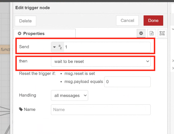
Trigger Camera Operation via Pulse UP
As the USB CAMERA operation only needs to be executed each time the OperationCommand value changes from 0 to 1, the Trigger Node in Node-Red is used.
Connect the Trigger Node to the Local OPC UA Client after the execution of the Node.
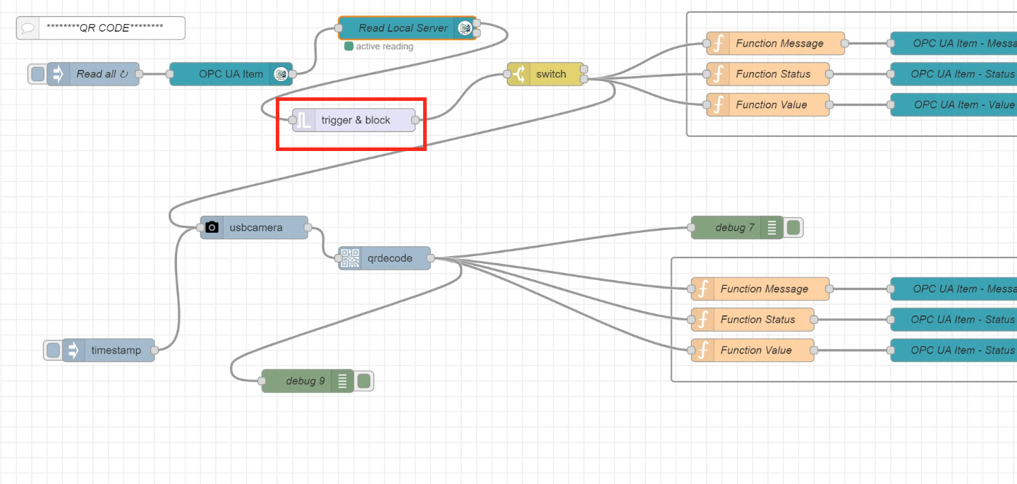
When the Trigger condition is fulfilled, the Payload value is sent to 1. The corresponding Node resets when msg.rest msg or payload=0 is received.
Check the Signal
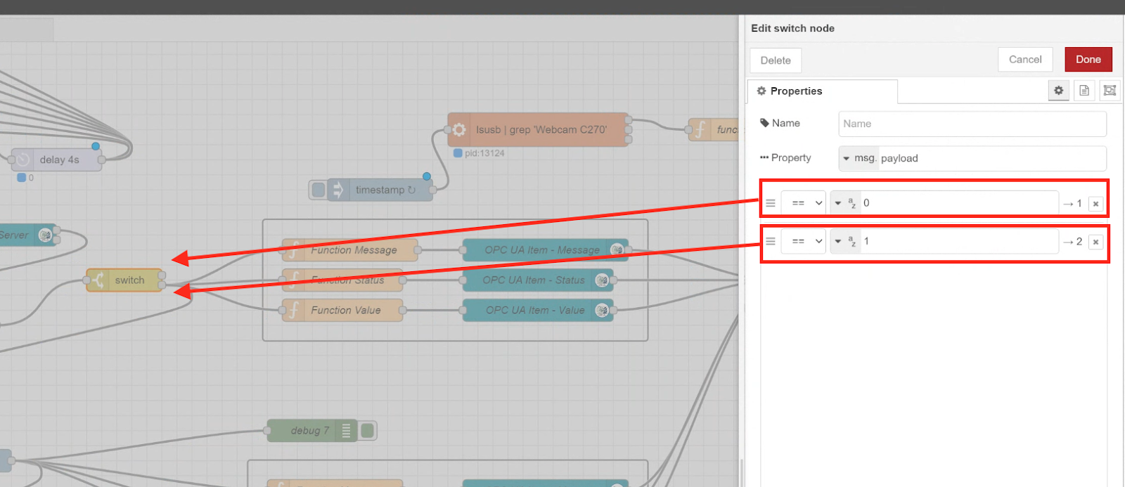
Next, switch Nodes are added and conditional decisions are made.
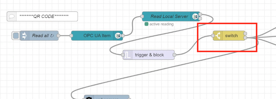
The switch Node can define multiple conditional decisions, this time only 0 and 1 were set, but in the case of 0, the image flows to the Flow above the Switch Node, and in the case of 1, the image flows to the Flow below.
Reflesh the Server Status
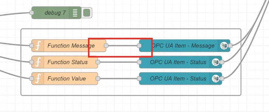
When a USB CAMERA is Triggered, the three Message/Status/Value variables in the OPC UA are initialized once. Then the Client connected to the OPC UA Server will also know that the Camera has been Triggered.
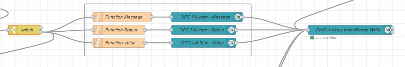
Setup Payload
Set a Payload Message for each Function Node.
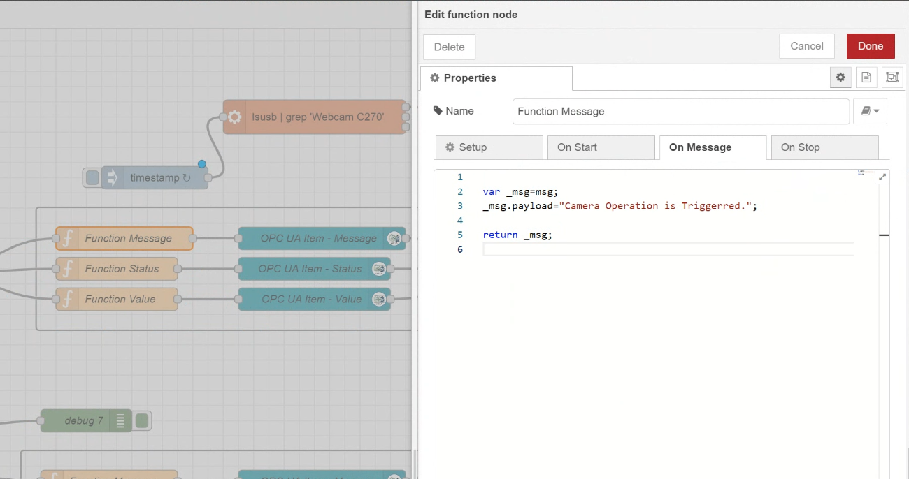
Function Message
| var _msg=msg; _msg.payload=”Camera Operation is Triggerred.”; return _msg; |
Function Status
| var _msg = msg; _msg.payload = -2; return _msg; |
Function Value
| var _msg = msg; _msg.payload = ” “; return _msg; |
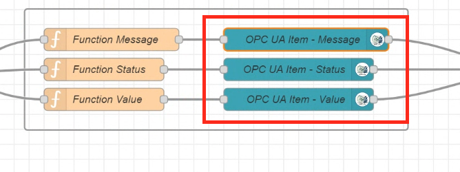
Passing payload to OPC UA Item
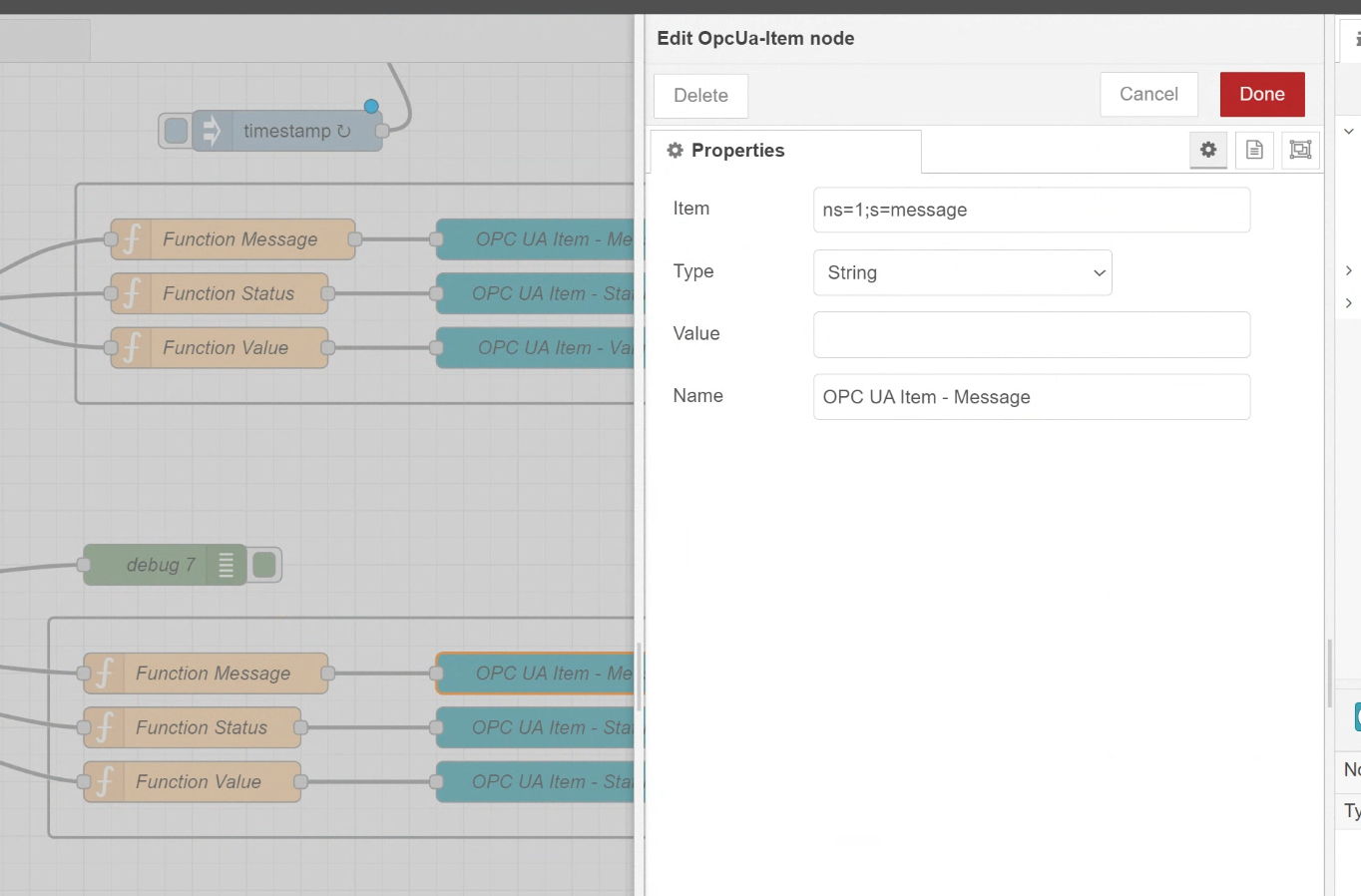
Set the Payload Message set in the Function Node earlier to the OPC UA Item.
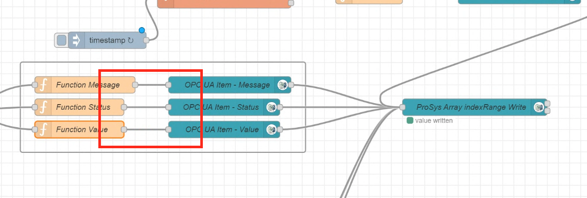
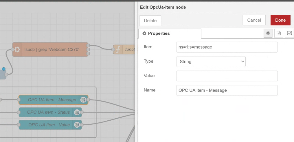
Configure Writing OPC UA Item
Set the OPC UA Item you want to write to the OPC UA Server.
The settings here have been explained earlier and will not be explained in detail.
Write Data to OPC UA Server
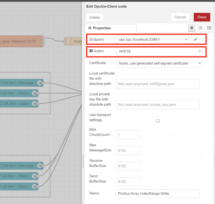
Next, add an OPC UA Client and connect it to the OPC UA Item you have just set up.
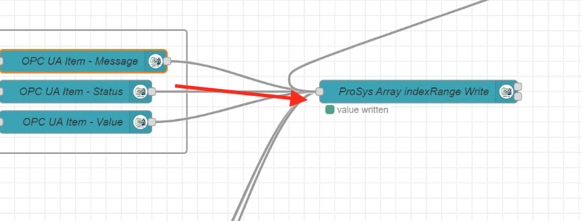
In the OpcUa-Client Node, set Endpoint to LocalHost and Action to WRITE.
Trigger the USB Camera
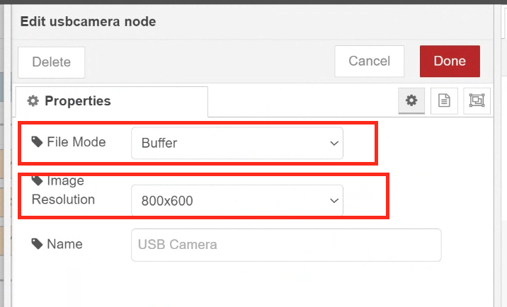
After updating the OPC UA Server variable Node, add a USB CAMERA Node to Trigger the USB CAMERA behavior.
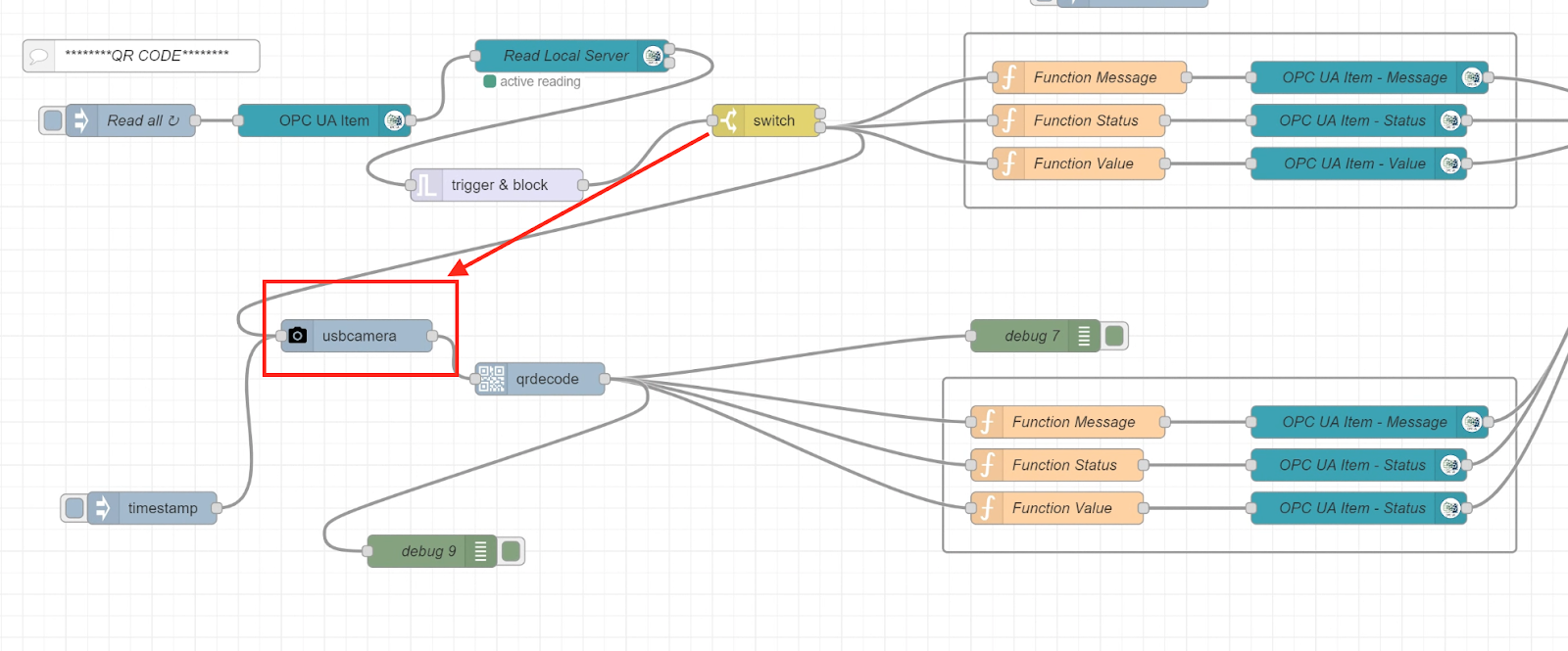
Set File Mode to Buffer and Image Resolution to around 800×600.
Decode the Images
Next, add a qrcode Node and connect it to the usb camera Node.
There are no items to set for qrcode Node.

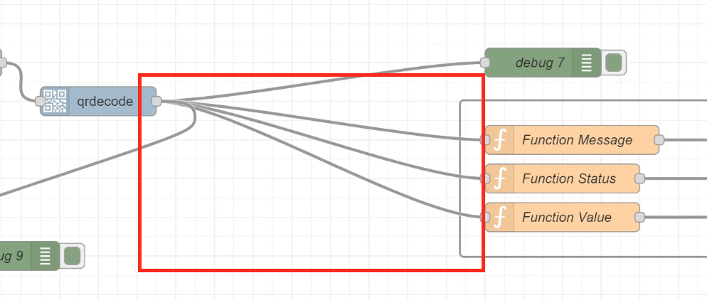
Reflesh the Result
we will feedback the reading result to OPC UA server.
The output of the qrcode and also the three Function Nodes are connected.
Configure the payload
Set the qrcode Node result to Payload Message.
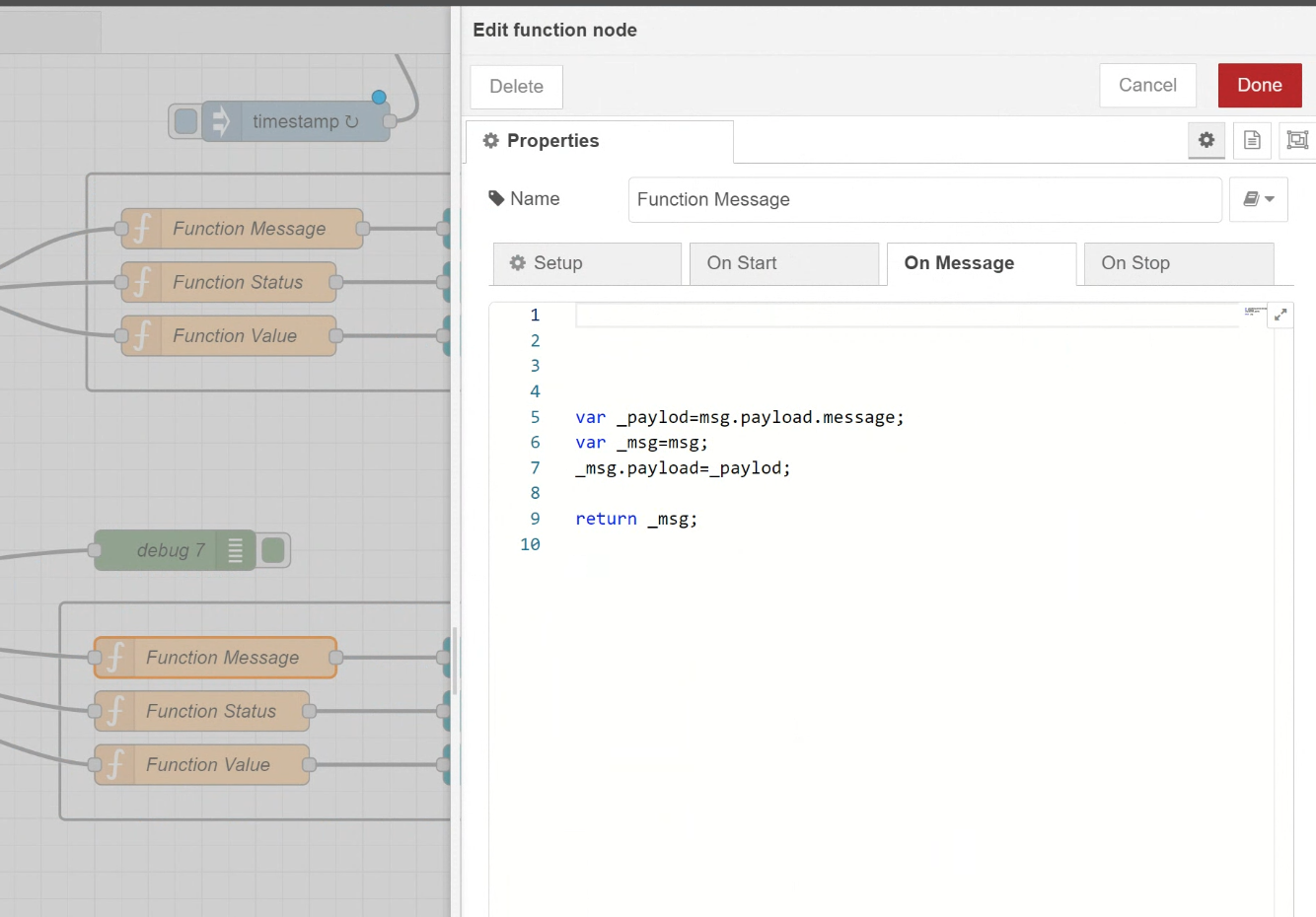
Function Message
| var _paylod=msg.payload.message; var _msg=msg; _msg.payload=_paylod; return _msg; |
Function Status
| var _paylod=msg.payload.status; var _msg=msg; _msg.payload=_paylod; return _msg; |
Function Value
| var _paylod = msg.payload.value; var _msg = msg; _msg.payload = _paylod; return _msg; |
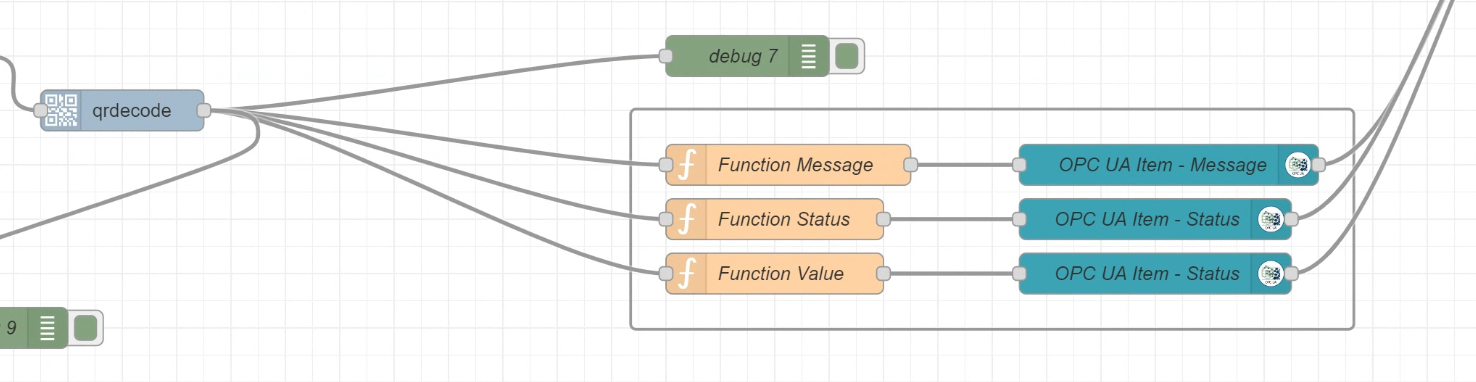
Configure OPC UA Item
The Function Node and the OPC UA Item are connected.
Set the Node variable you want to update to Opc-UA-Item.
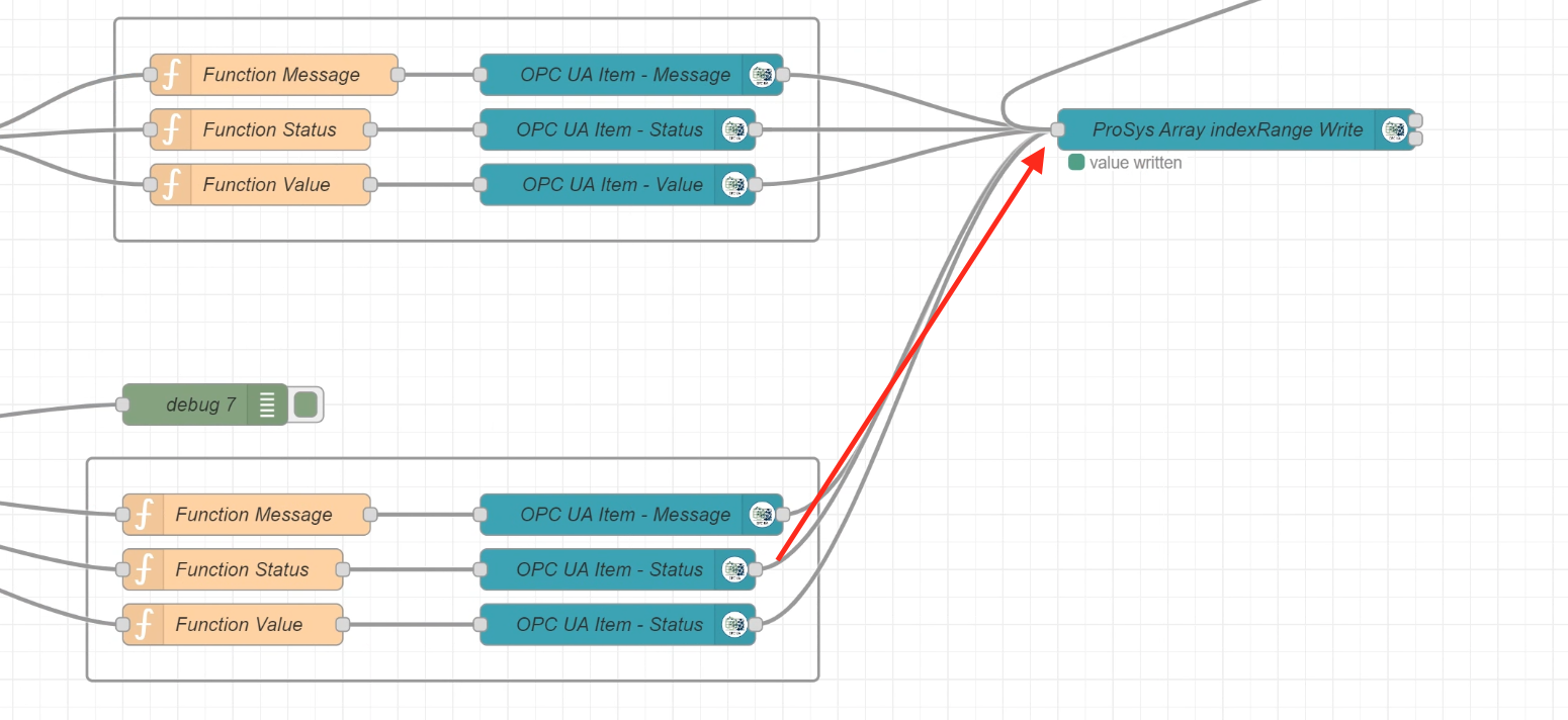
Write to OPC UA Server
Finally, connect with the output of the OPC UA Item so that the Node variable is written to the OPC UA Server.
Check the Camera Status
The last section describes the Flow to CHECK the status of the USB camera.
Trigger
This is a Node that runs repeated every 1s.
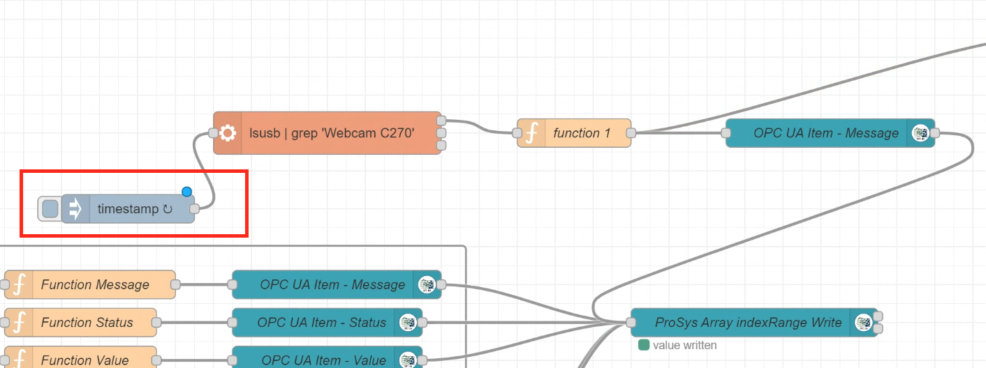
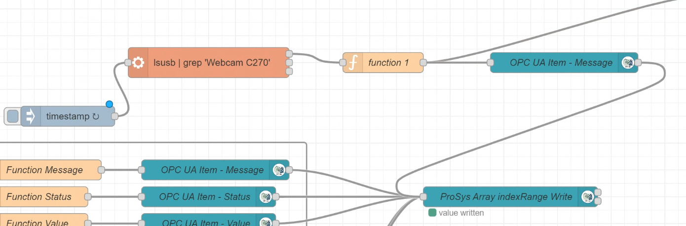
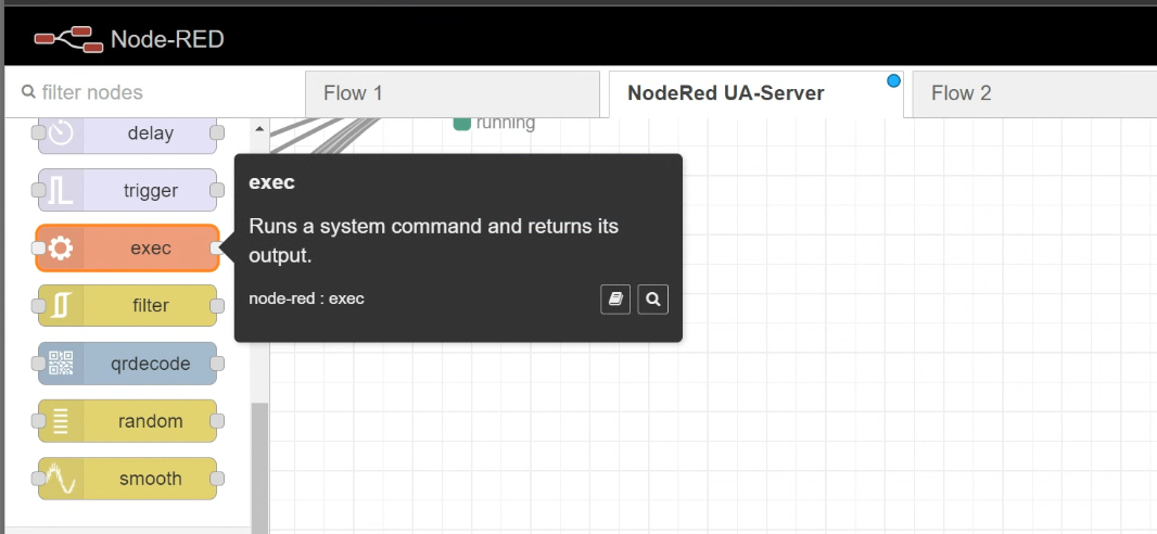
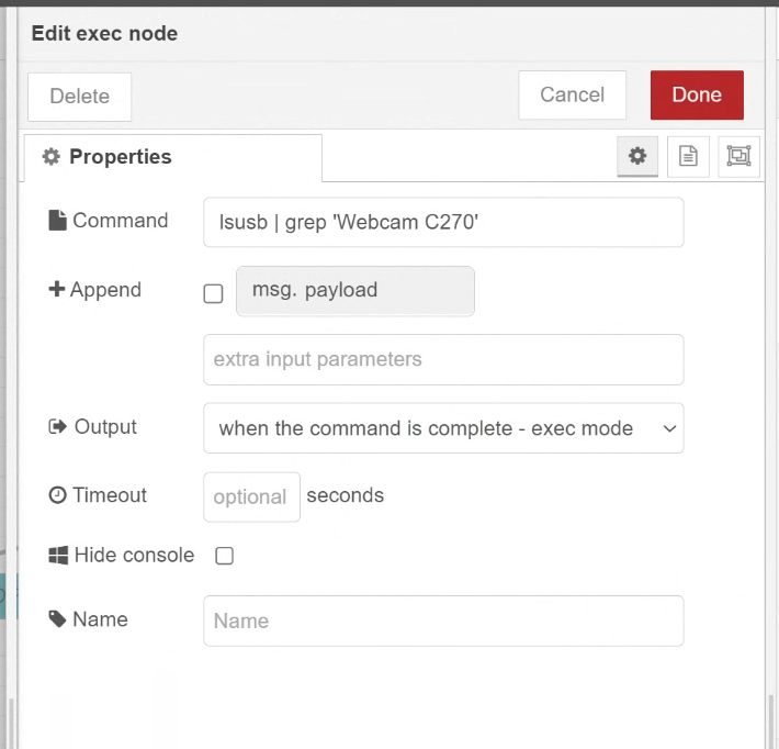
Execute Command
Next, add an exec Node. You can use this Node to execute System Command.
As mentioned at the beginning of the article, you can use this command to extract the webcam string.
Check the result
Add a Function Node and use the execution result of the exec Node to reflect the state of the USB CAMERA.
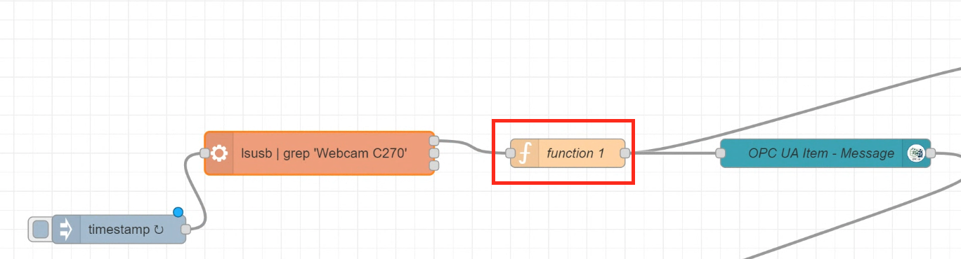
If any text is read from Webcam c270 is present, the Raspberry PI is able to recognise the USB CAMERA, so it returns 1. Otherwise, it returns 0.
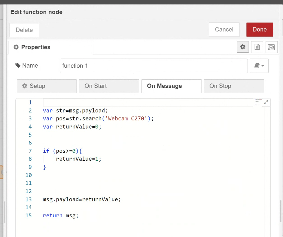
| var str=msg.payload; var pos=str.search(‘Webcam C270’); var returnValue=0; if (pos>=0){ returnValue=1; } msg.payload=returnValue; return msg; |
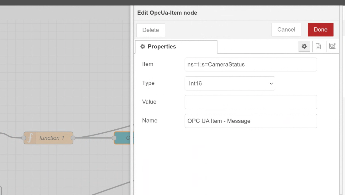
Configure the OPC UA Item
Set up a Node to write to the OPC UA Server.
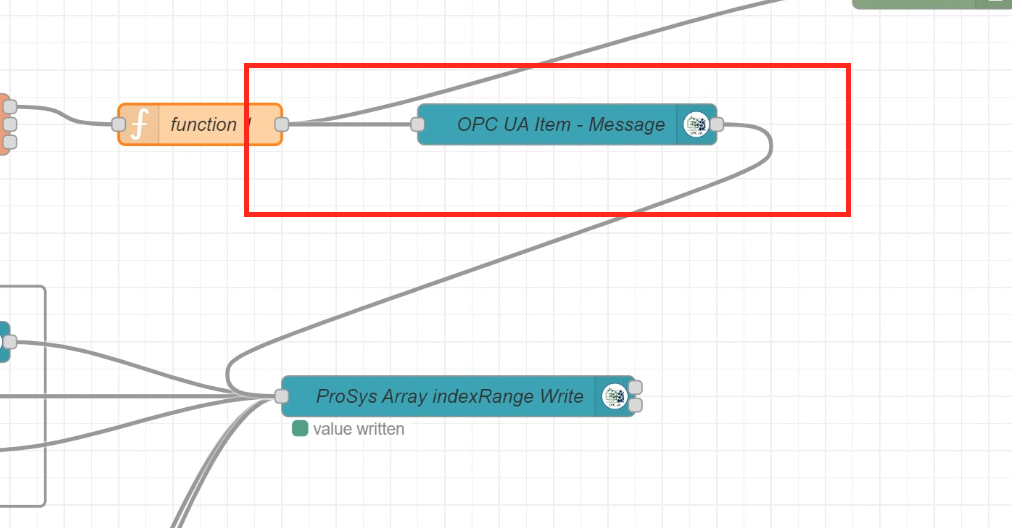
The settings here have been explained earlier, so.
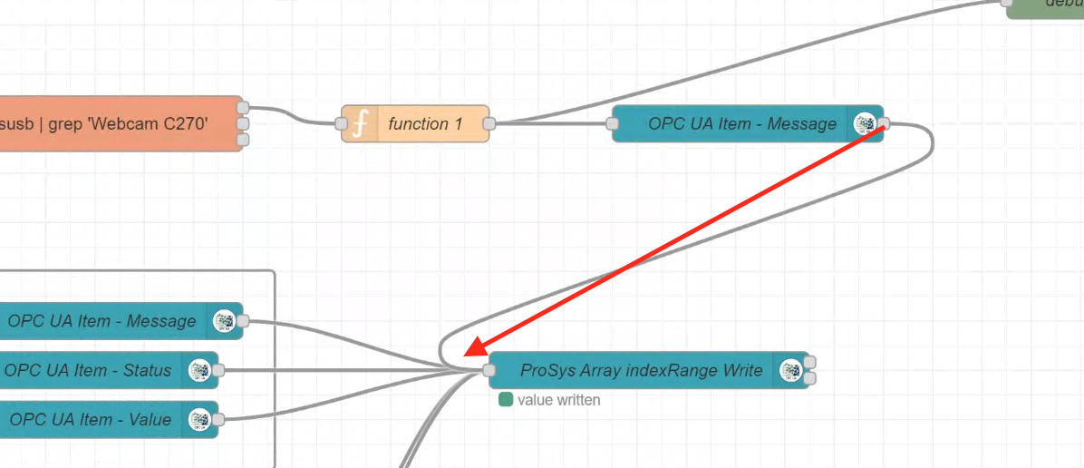
Write the Data to OPC UA Server
Ensure that the data is written to the OPC UA Server. This completes the Raspberry PI side.
Beckhoff Side
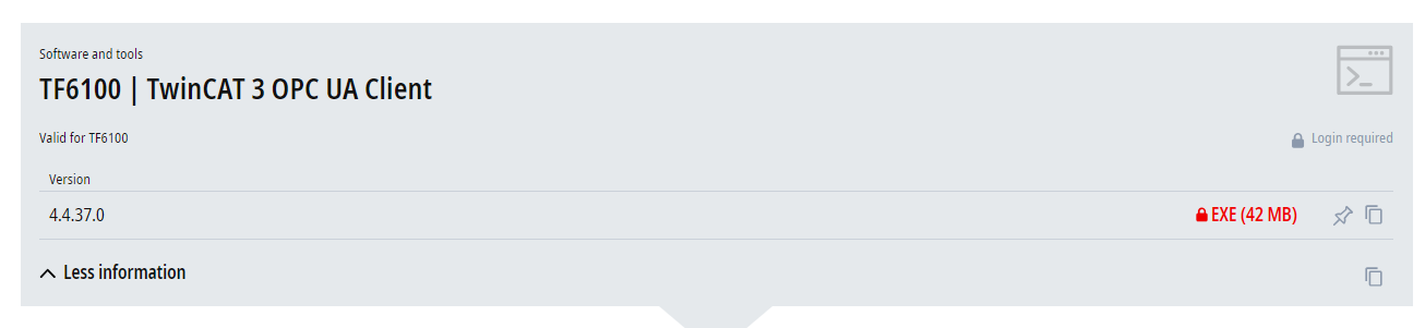
Install Packages
To use the OPC UA Client with Beckhoff TwinCAT3, install the following Package.
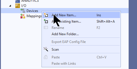
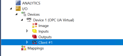
Add Devices
Add new Devices under Devices>Add New Item.
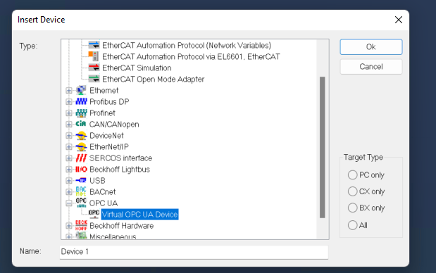
OPC UA>Virtual OPC UA Deviceを選び>Okします。
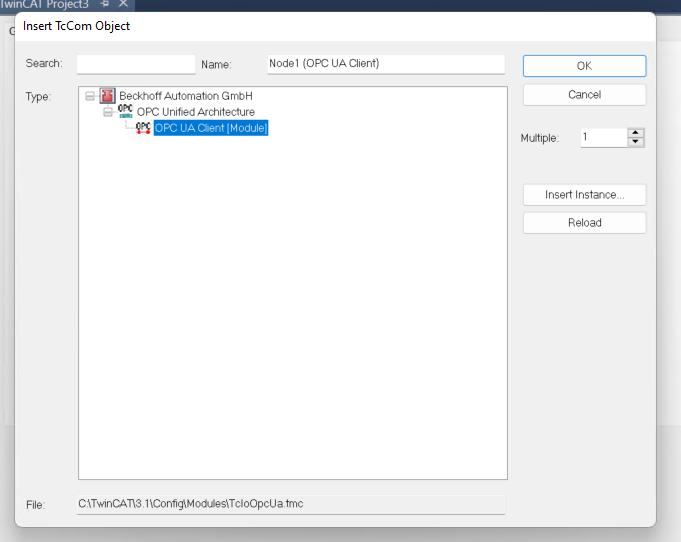
Add OPC UA Client
Device>Add New Itemで新しいOPC UA Clientを追加します。
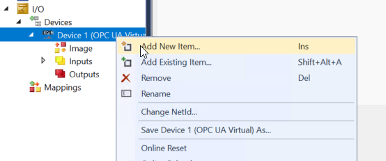
Add the OPC UA Client (Module).
SelectEndpoint
To configure the connection settings for the Raspberry pi, click on the Client you have just added.
Click Select Endpoint.
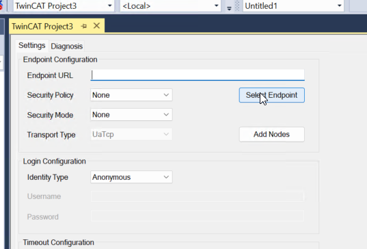
The Endpoint Discovery screen appears.
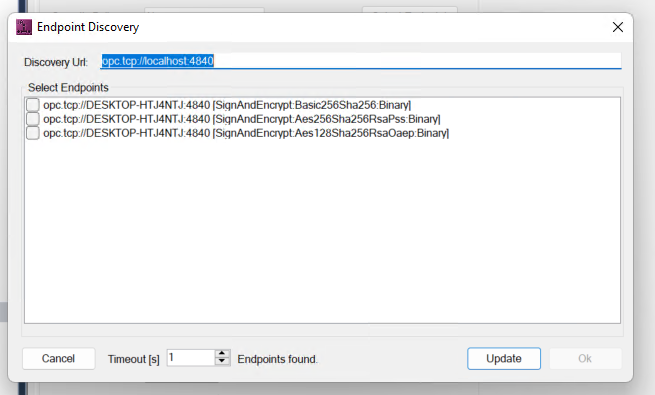
Enter the OPC UA Server Endpoint of the RaspberryPI in the Discovery Url.
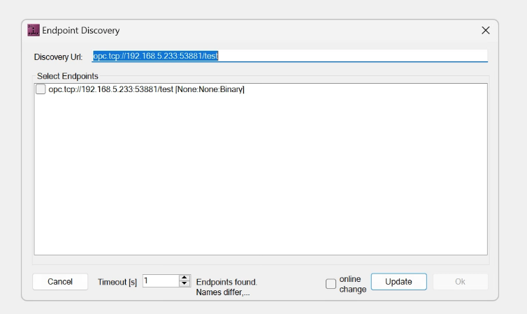
Select the Endpoints to be connected to the RaspberryPI.
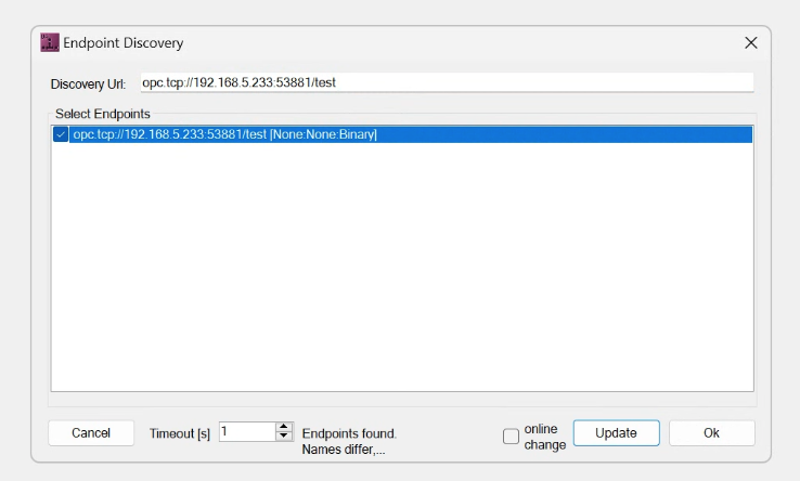
Done!
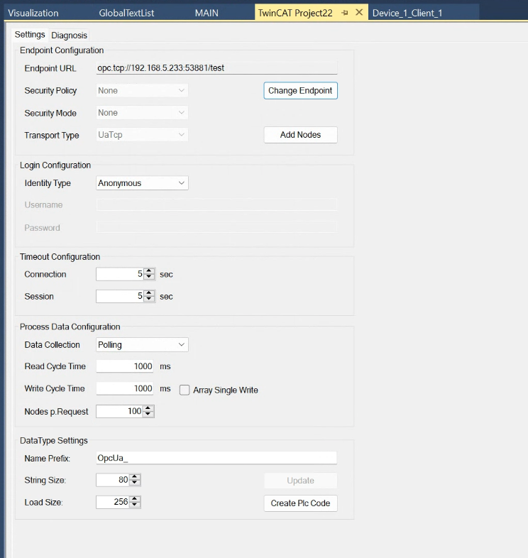
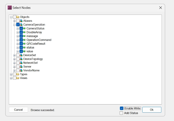
Add Nodes
All the Nodes required in this article are stored in a Folder called CameraOperation, so put a Check in Enable Write and proceed with OK.
Add PLC
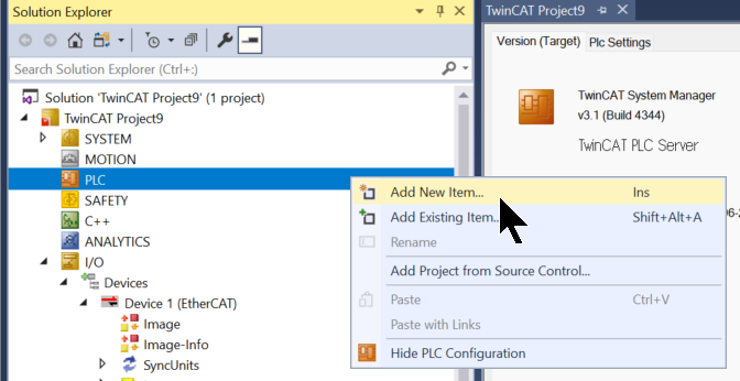
Right-click on PLC>Add New Item to add a new PLC project.
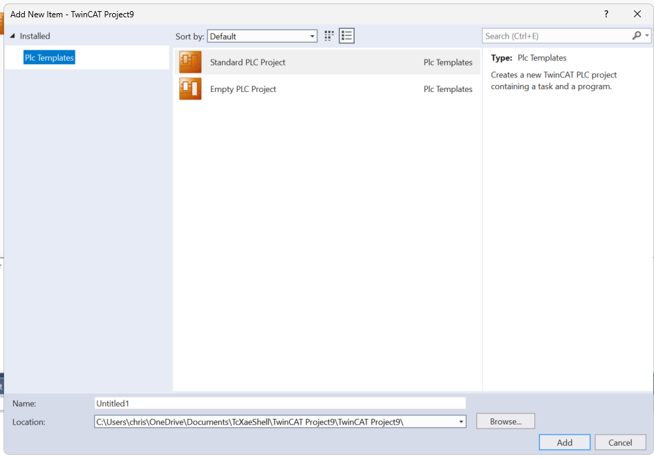
Select Standard PLC Project and proceed with Add.
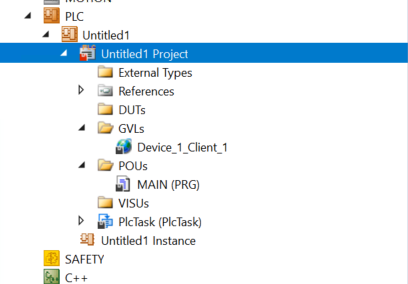
Create GVL
Automatically generate GVL using Create Plc Code.
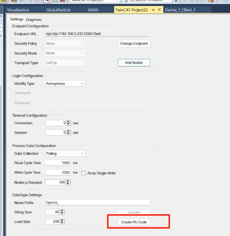
Done!
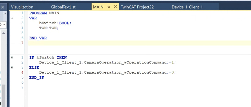
MAIN
This is a simple program that writes OperationCommand to 1 when bSwitch is turned on and to 0 when it is turned off.
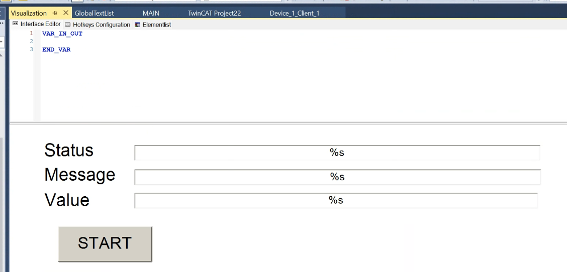
Screen
This is a simple screen shot of the QR Code results and the Start button to Trigger.
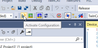
Activate Configuration
Finally, use Activate Configuration to Download the project to Runtime.
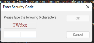
If there are not enough licences, enter the Trial licence.
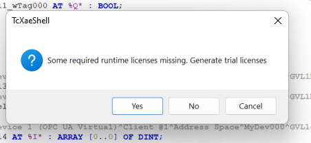
As long as you enter the Magic code, you can use it for 7 days. After 7 days, Runtime will stop once and you can activate the Trial licence one more time.
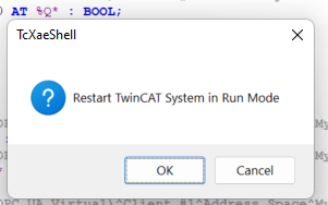
Switch the TwinCAT to Run Mode.
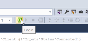
Login
Login to monitor results.
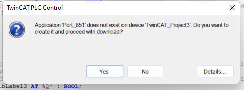
Proceed with Yes.
Start
Start Runtime with the Start button.
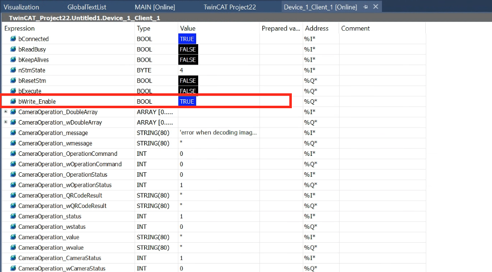
Write Enable
Set bWrite_Enable in the GVL to True. Also, bConnected=True, so it is successfully connected to the OPC UA Server.
Result
You can check the operation in this video.