This article is the second episode of creating a Safety Program from Beckhoff’s TwinSAFE. In this article, we will introduce TwinCAT Groups, Function Block Properties and Signal Type, and create a simple emergency stop application with FunctionBlock safeEstop, the standard ESTOP control in TwinSAFE.
The article is written with the intention that anyone can follow the Work-Flow as much as possible and build absolutely anything. Thank you in advance for your cooperation.
Thanks!
This article was made possible thanks to Beckhoff Automation Corporation, that lent us their equipment. Thank you very much.
ベッコフ日本法人ベッコフオートメーション株式会社
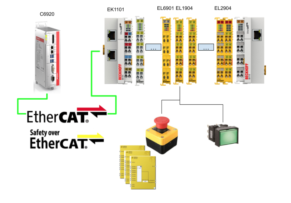
IPC6920-005, EL6910, and EL1904 were loaned to us by Beckhoff Automation K.K. Beckhoff Automation was established in 1980 and is a leading German company in the introduction of open automation systems based on PC-based control technology. Beckhoff Automation was established in 1980 and is a leading German company in the introduction of open automation systems based on PC-based control technology.
Beckhoff Automation Japan K.K. established its headquarters in Yokohama in 2011 and its Nagoya office in 2017.

This is the website of Beckhoff Automation K.K., Beckhoff’s Japanese subsidiary.
Please feel free to contact them.
https://www.beckhoff.com/ja-jp/
Reference Link
Blog
Video
Beckhoff.Let’s play with TwinSAFE_Part1.EN
TwinSAFE groups
TwinSAFE Groups are a simple, decentralized structure that allows different safety zones to be controlled from different machines. The outputs of the corresponding group will be turned off.
VAR
In TwinSAFE Group, you can control and get the status of a Group from the Variable Mapping tab, and you can list all Variables from Variable Mapping>Group Ports.
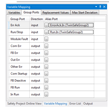
Input
| Group Pots | Description |
| Err Ack | Reset TwinSAFE Group error.Must be tied to a Standard variable. |
| Run/Stop | True=TwinSAFE Group activated, False=TwinSAFE Group deactivatedMust be tied to a Standard variable. |
| Module Fault | Connects to the error output of another module (e.g., EK1960) |
Output
| Group Pots | Description |
| Comm Err | One or more connections are experiencing communication errors |
| FB Err | FB encountered an error |
| Module Fault | Connects to the error output of another module (e.g., EK1960) |
| Com Startup | One or more Connections were activated. |
| FB Deactive | TInvalidated by winSAFE Group. |
| FB Run | TwinSAFE FB is running? |
| In Run | TwinSAFE Group is in Run Mode? |
Group State
| Value | Status | Description |
| 1 | RUN | Input Run=1 Safety Group is error-free and all connections are up and running. |
| 2 | STOP | Input Run=0 |
| 4 | ERROR | TwinSAFE Group has error |
| 5 | RESET | Error resolution of TwinSAFE Group, Err Ack signal is True |
| 6 | START | Indicates that the TwinSAFE Group has not started up any connections. |
| 7 | ESTOPERROR | |
| 16 | DEACTIVE | TwinSAFE Group is disabled. |
| 17 | WAITCOMERROR | Passivate function is selected |
Group Diag
| Value | Status | Description |
| 0 | No Error | |
| 1 | FBERROR | One or more FBs are in error. |
| 2 | COMERROR | One or more connections are in error. |
| 3 | MODULEERROR | ModuleFault=True |
| 4 | CMPERROR | Power-On Analog Value Check Error |
| 6 | DEACTIVATEERROR | |
| 6 | RESTARTERROR | Either the EtherCAT communication of the TwinSAFE Logic Program has been restarted or the TwinSAFE Logic Program is not reloaded when the User logs in. |
FB port properties
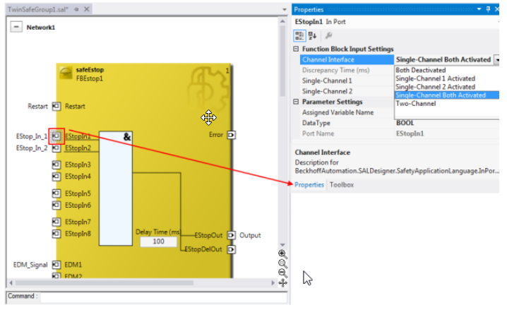
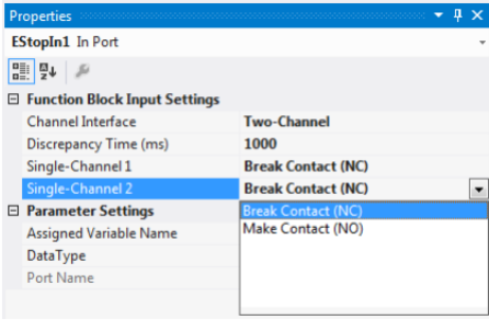
Each Function itself and each Port also has Properties that can be configured. For example, as shown in the figure below, if you select the Port input in SafeESTOP and choose Properties, you will see a list of settings such as the Interface type, data type, etc. for the Channel…
Implementation
Function Block
We will explain the FB that used in this tutorial.
Signal Type?
Here is the Signal Type for all Safety FB in TwinSAFE.
| Type | Description |
| TwinSAFE-In | TwinSAFE Inputs |
| Standard-In | %Q* Standard Variables in PLC |
| FB-Out | TwinSAFE Function Block’s Ouput |
| TwinSAFE-Out | TwinSAFE’s Output |
| Standard-Out | %I* Standard Variables in PLCs |
| FB-In | TwinSAFE Function Block’s Input |
DECOUPLE
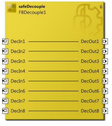
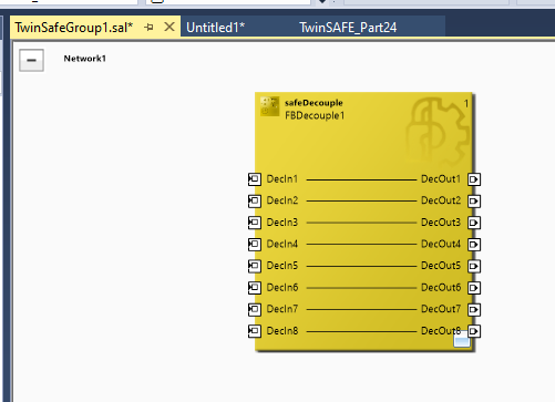
FB_Decouple is a Function Block for disconnecting signals from the TwinSAFE Connection. This Function Block has 8 inputs and 8 outputs, and the corresponding numbered DecInX flows directly to DecOutX. Here is another basic concept: TwinSAFE I/O Terminals and TwinSAFE Connections are assigned to TwinSAFE Groups, and the FB_Decouple can distribute TwinSAFE Connections to other TwinSAFE Groups. FB_Decouple can distribute TwinSAFE Connection to other TwinSAFE Groups.
safeEstop
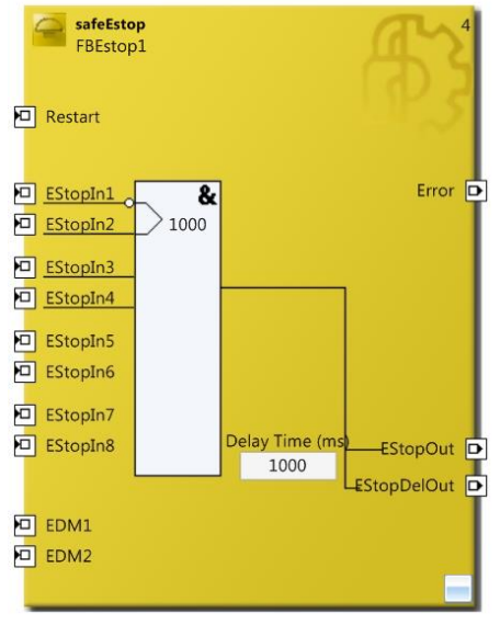
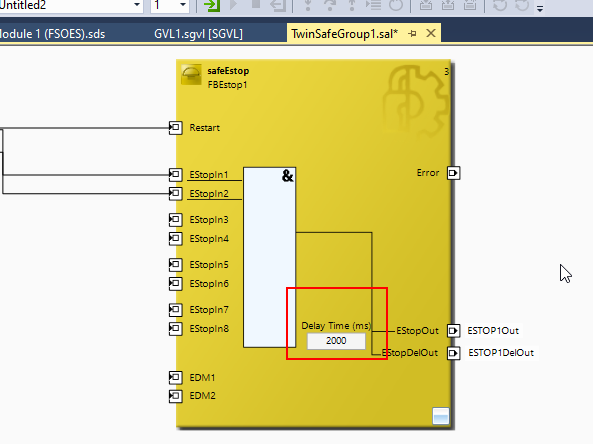
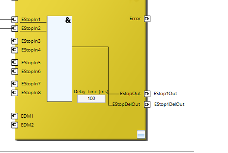
FB_ESTOP has up to 8 emergency stop inputs (at EStop1 through EStop8), and each port can also be set to Breach Contact (NO) or Make Contact (NC).
Its Function Block has two outputs: EStopOut reacts immediately to the ESTop signal, while EStopDelOut is parameterized for Time-Delay.
Also, once FB_ESTOP transitions from the ESTOP signal to the Safe state, the Block must be reset from the Restart signal.
Finally, the EDM Feedback Loop signal can be set to FB_STOP by connecting Function Block EStopOut directly to EDM1 and EStopDelOut directly to EDM2. If the EDM does not have a “True” signal, FB_STOP will be set to Error=True instead.
As a further supplement, the input Port combinations are EStopIn1/EStopIn2, EStopIn3/EStopIn4, EStopIn5/EStopIn6, and EStopIn7/EStopIn8 Pair, and the signal combinations can be Single or Dual. If the ESTOP input time exceeds the monitoring time (Discrepancy Time), FB Error will be True.
If the FB Error Flag is True, the output is False and the Error Output is True.
VAR INPUT
| Variable | Permitted Type | Data Type | Desription |
| Restart | TwinSAFE-InFB-OutStandard-Iin | BOOL | Pulse activation signal required by TwinSAFE Group for start-up, etc. |
| EStopIn1 | TwinSAFE-InFB-Out | BOOL | 1st emergency stop signal |
| EStopIn2 | TwinSAFE-InFB-Out | BOOL | 2nd emergency stop signal |
| EStopIn3 | TwinSAFE-InFB-Out | BOOL | 3rd emergency stop signal |
| EStopIn4 | TwinSAFE-InFB-Out | BOOL | 4th emergency stop signal |
| EStopIn5 | TwinSAFE-InFB-Out | BOOL | 5th emergency stop signal |
| EStopIn6 | TwinSAFE-InFB-Out | BOOL | 6th emergency stop signal |
| EStopIn7 | TwinSAFE-InFB-Out | BOOL | 7th emergency stop signal |
| EStopIn8 | TwinSAFE-InFB-Out | BOOL | 8th emergency stop signal |
| EDM1 | TwinSAFE-InFB-OutStandard-Iin | BOOL | When the EDM signal is enabled, the Safe output is True. |
| EDM2 | TwinSAFE-InFB-OutStandard-Iin | BOOL | If the Delay output channel (EStopDelOut) is the Feedback signal and the EDM signal is enabled, the Safe output will be True under the condition that EDM2 is a True signal. |
VAR OUTPUT
| Variable | Permitted Type | Data Type | Desription |
| Error | TwinSAFE-InFB-InStandard-OutLocal-Out | BOOL | True=Input Pair different state than the set time or there is a Feedback Loop error. |
| EStopOut | TwinSAFE-InFB-InStandard-OutLocal-Out | BOOL | ESTOP status output, True=Normal |
| EStopDelOut | TwinSAFE-InFB-InStandard-OutLocal-Out | BOOL | ESTOP+Delay status output, True=Normal |
Diagnostics Information
16Bit
| Bit | Description |
| 0 | Error – Input Group1 |
| 1 | Error – Input Group2 |
| 2 | Error – Input Group3 |
| 3 | Error – Input Group4 |
| 4 | EDM Error – EDM1 |
| 5 | EDM Error – EDM2 |
| 6 | – |
| 7 | – |
| 8 | “Safe Input after Disc Error” Option is enabled and set to True when the Input Group status is different. |
| 9 | “Safe Input after Disc Error” Option is enabled and set to True when the Input Group status is different. |
| 10 | “Safe Input after Disc Error” Option is enabled and set to True when the Input Group status is different. |
| 11 | “Safe Input after Disc Error” Option is enabled and set to True when the Input Group status is different. |
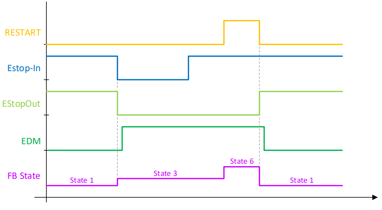
State Information
| Value | Description |
| 0 | 未定義 |
| 1 | The FB_ESTOP module is now in RUN State and there is no ESTOP in Fail-Safe State.Error=0EStopOut=1EStopDelOut=1 |
| 2 | FB_ESTOP module is now in STOP State and FbRun is False.Error=0EStopOut=0EStopDelOut=0 |
| 3 | FB_ESTOP module is now in SAFE State and at least one ESTOP input is Fail-safe.Error=0EStopOut=0EStopDelOut=0 |
| 4 | FB_ESTOP module is now in Error State and at least one ESTOP input is Fail-safe.Error=1EStopOut=0EStopDelOut=0 |
| 5 | FB_ESTOP module is now in Reset State, error resolved, waiting for ErrAck resetError=0EStopOut=0EStopDelOut=0 |
| 6 | FB_ESTOP module is now in START State, waiting for Restart signalError=0EStopOut=0EStopDelOut=0 |
| 8 | FB_ESTOP module is now in DELAYOUT State, Safet state requested, but ESTOPDelOut still True.Error=0EStopOut=0EStopDelOut=1 |
Channel Interface
| Settings | Description |
| Both Deactivated | Disable two Channels as well. |
| Single-Channel 1 Activated | Channel1:Single-Channel EvaluationChannel2:invalid |
| Single-Channel 2 Activated | Channel1:invalidChannel2:Single-Channel Evaluation |
| Single-Channel Both Activated | Channel1:Single-Channel EvaluationChannel2:Single-Channel Evaluation |
| Two-Channel | Channel 1 and Channel 2 are also enabled and evaluated within the Discrepancy Time. |
Channel Contact
Flow
Connect to IPC
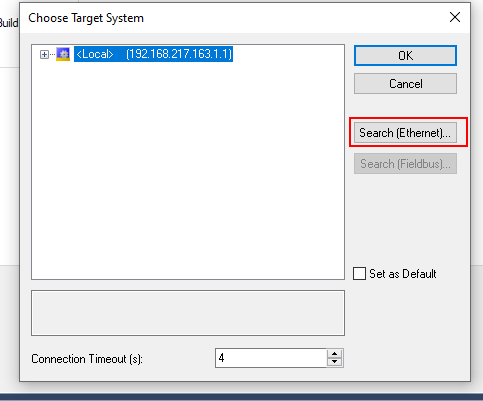
Set the IPC and Runtime of Beckhoff to be connected in SYSTEM>Choose Target.

Search(Ethernet) for Runtime.
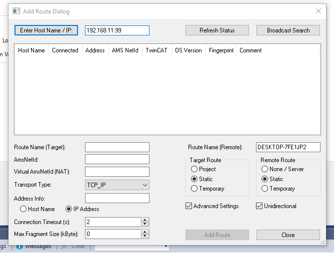
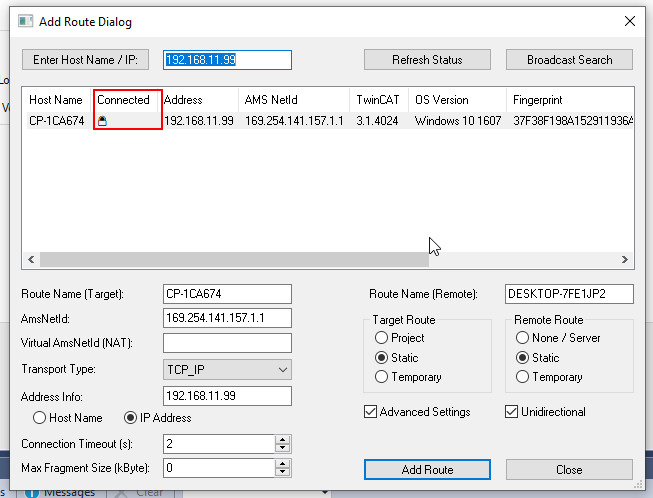
Enter Host Name/IP, type Ip, and press Enter to search.
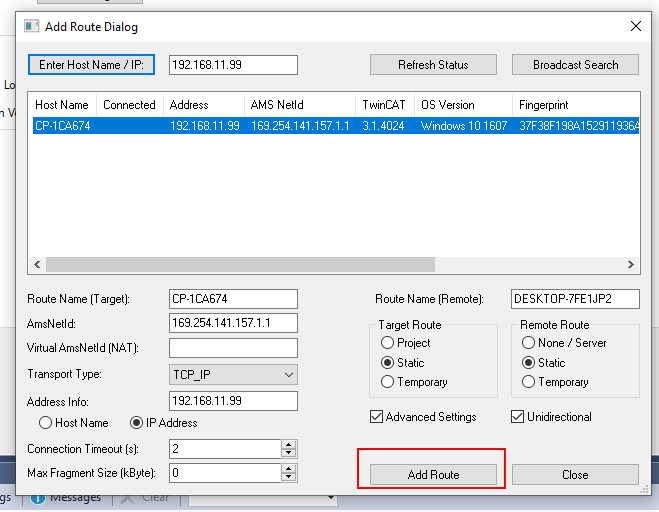
Add Route.
Check the Secure ADS check box and enter your password.
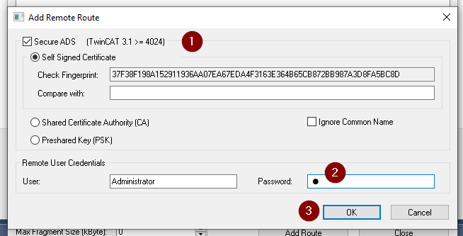
Connected!
Configuration
Add EtherCAT Master
I/O>Devices>Add New Item.
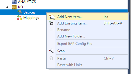
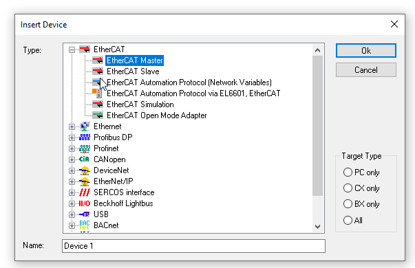
Select EtherCAT>EtherCAT Master>Ok.
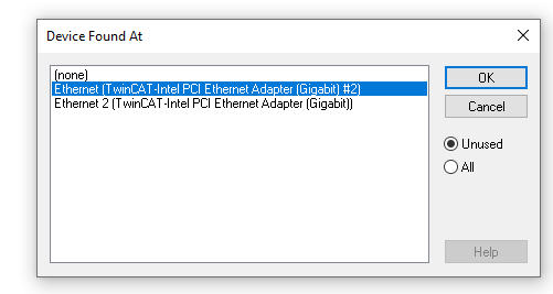
Configure the Network Interface Card to be used as EtherCAT Master>Ok.
Scan
EtherCAT Master right click>Scan to find the EtherCAT Node.
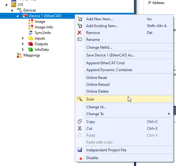
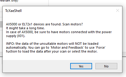
Motor does not need to be searched for in this article, so proceed with No.
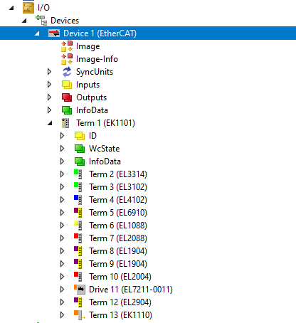
Done!
Inside you found the main character of TwinSAFE, EL6910.
ADD PLC
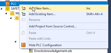
PLC>Add New Item.
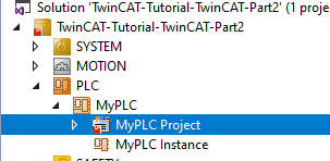
PLCs have been added.
DUT
DUT_safeESTOP_InfoData
This structure here was created to store FBESTOP’s State and Diag information.
| TYPE DUT_safeESTOP_InfoData : STRUCT State AT %I* :USINT; Diag AT %i*:UINT; END_STRUCT END_TYPE |
DUT_SafetygroupsStatus
This structure here was created to store TwinSAFE control and information.
| TYPE DUT_SafetygroupsStatus : STRUCT //Standard Input from Safety Group RunStop AT %Q* :BOOL; ErrorAck AT %Q* :BOOL; //Standard Output from Safety Group Com_erro AT %I* :BOOL; Com_Startup AT %I* :BOOL; FB_Deactive AT %I* :BOOL; FB_Err AT %I* :BOOL; FB_Run AT %I* :BOOL; In_Run AT %I* :BOOL; Other_Error AT %i* :BOOL; END_STRUCT END_TYPE |
eDUT_safeESTOP_State
This structure is designed to indicate the current state from the State of FBESTOP.
| {attribute ‘qualified_only’} {attribute ‘strict’} TYPE eDUT_safeESTOP_State : ( undefined :=0 ,RUN :=1 //No Error,Error=0,EStopOut=1,EStopDelOut=1 ,STOP :=2 //Stop State,Error=0,ErroStopOut=0,EStopDelOut=0 ,SAFE :=3 //Safe State,Error=0,ErroStopOut=0,EStopDelOut=0 ,ERROR :=4 //Error State,Error=1,ErroStopOut=0,EStopDelOut=0 ,RESET :=5 //Reset State,Error=0,ErroStopOut=0,EStopDelOut=0 ,START :=6 //Start State,Error=0,ErroStopOut=0,EStopDelOut=0 ,DELAYOUT :=8 //Delay Out State,Error=0,ErroStopOut=0,EStopDelOut=0 ); END_TYPE |
Function Block
FB_safeSTOP_InfoData
The safeETOP_InfoData in this Function Block directly links the Diag and State of the FBEStop.
| FUNCTION_BLOCK FB_safeSTOP_InfoData VAR_INPUT END_VAR VAR_OUTPUT END_VAR VAR safeETOP_InfoData :DUT_safeESTOP_InfoData; END_VAR |
PROPERTY DiscrepanyError : BOOL
Get whether each Channel is error-free.
| DiscrepanyError:= (safeETOP_InfoData.Diag AND 2#0000_1111_0011_1111 ) <>0; |
PROPERTY ESOTPState : USINT
Obtains the current FBStop status.
| ESOTPState:=safeETOP_InfoData.State; |
MAIN
The MAIN program is here, just to check if FBEstop is normal or if there is an error.
| PROGRAM MAIN VAR safeESTOP1 :FB_safeSTOP_InfoData; ESTOPNormal :BOOL; Error :BOOL; END_VAR ESTOPNormal:=safeESTOP1.ESOTPState = eDUT_safeESTOP_State.RUN; Error:=safeESTOP1.DiscrepanyError; |
GVL
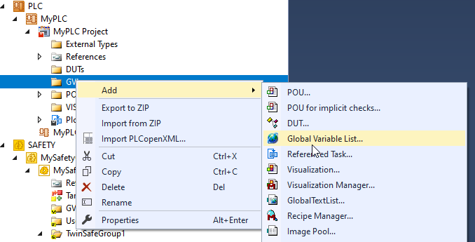
Next, add the GVL: GVL>Add>Global Variable List.
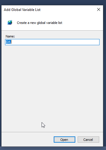
Enter a GVL name and add it with >Open.
Define variables to link with TwinSAFE Group.
| {attribute ‘qualified_only’} VAR_GLOBAL // TwinSafetGroup1 :DUT_SafetygroupsStatus; END_VAR |
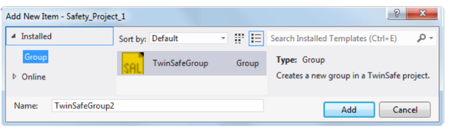
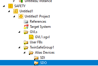
Add Safety Group
Add a Safety Group by going to SAFETY>Right click>Add New Item.
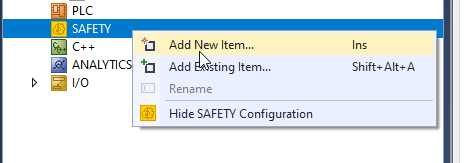
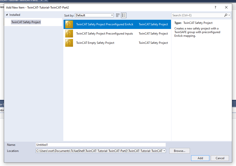
Again, select TwinCAT Safety Project Preconfigured ErrAck>Add.
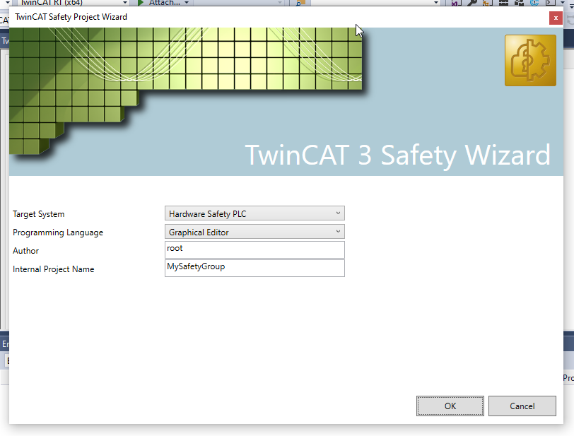
Set the Target System to Hardware Safety PLC.
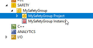
Safety Group has been added!
Set Target System
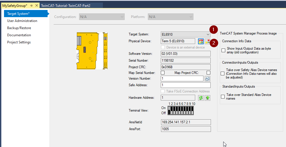
Open the Target System settings screen.
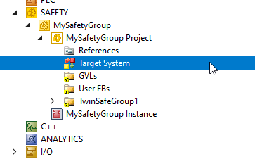
As mentioned in the previous article, select EL6910 as the Target System and set the EL6910 to be connected in Physical Device.
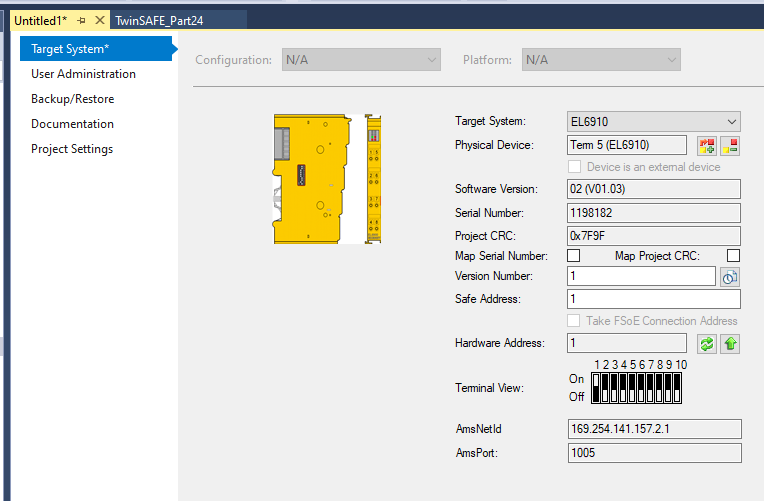
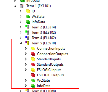
The actual EL6910 is now Term 5 of EK1101, so select Term5 and press >Ok.
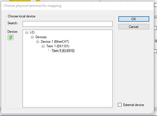
Done!
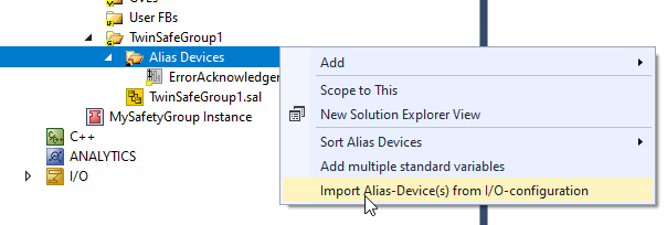
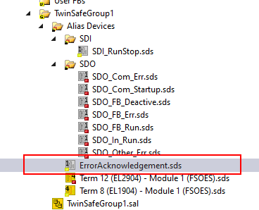
Import Alias-Devices(s) from I/O-Configuration
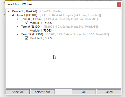
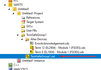
Import Safety IO Terminals connected via EtherCAT to Alias Devices: SafetyGroup>Alias Devices>Import Alias-Device(s) from I/O-configuration.
The Term8 EL1904 and Term12 EL2904 will be used in this project.
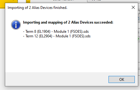
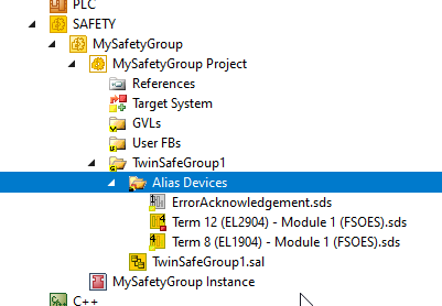
Import succeeded!
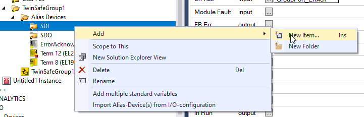
Add DI
Add a Digital input/Digital Output Slot to link to the Standard variable in the User Program of the PLC.
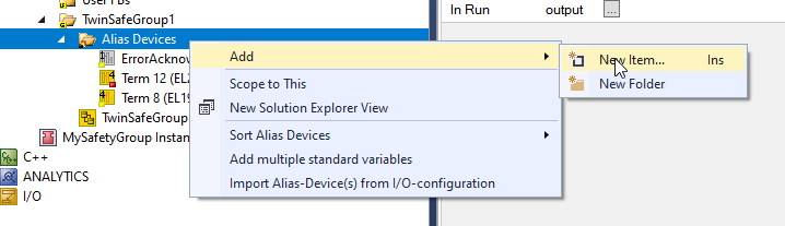
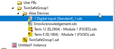
1 Select Digital Input(Standard) >Add.
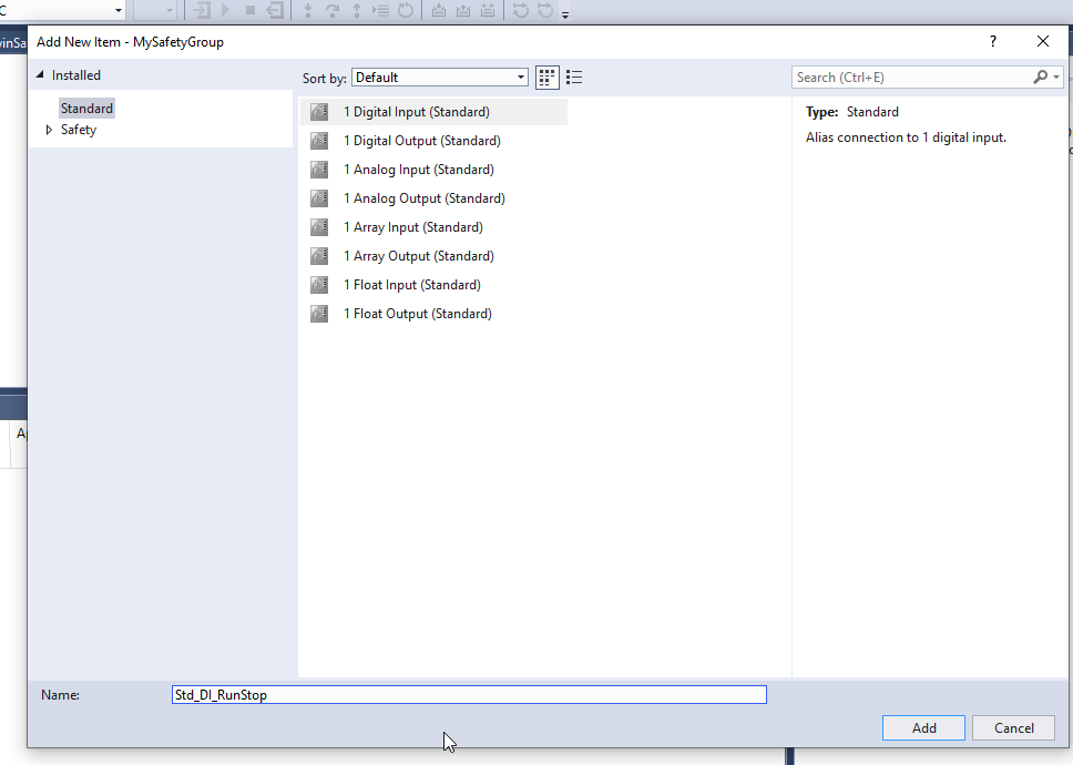
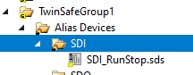
Bool type Digital Input(Standard) Slot is added.
Group your Variables!
As the number of modules grows, it is recommended to manage slots by Folder: Alias Devices>Add>New Folder.
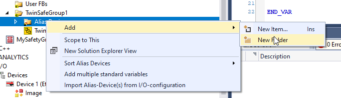
Folderが追加されました。
You can also add a new slot by selecting Folder>Add>New Item.
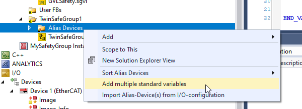
Add Multiple stand variables
If you find it tedious to add them one by one, you can also generate slots in batches by going to Alias Devices>Add multiple standard variables.
Name is the name of the Slot to be added.
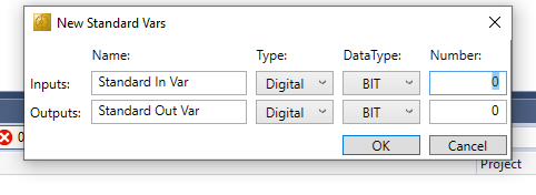
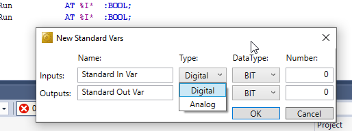
Next, set the Type. For example, Output can be changed to Digital or Analog.
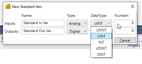
And if Analog is set, Data Type can also be constructed from USINT/UINT/INT/UDINT/DINT.
Now, let’s assume that Inputs/Outputs are a_in/a_out, Type is Digital, Data Type is BIT, and 10 pieces are generated.
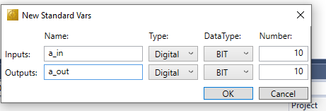
Thus, TwinCAT generates variables like name_1, name_2… and so on. This is a very useful feature.
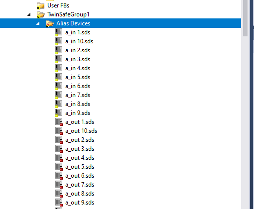
DIDO Signals
Now, for this article, I created several Standard Digital Input/Outputs because I want to pass the state of the TwinSAFE FB Group to Standard PLC.

Safety Program
Finally, create another Safety Program: open TwinSafeGroup.sal.
Add safeDecouple
Add SafetDecouple Function from Tools.
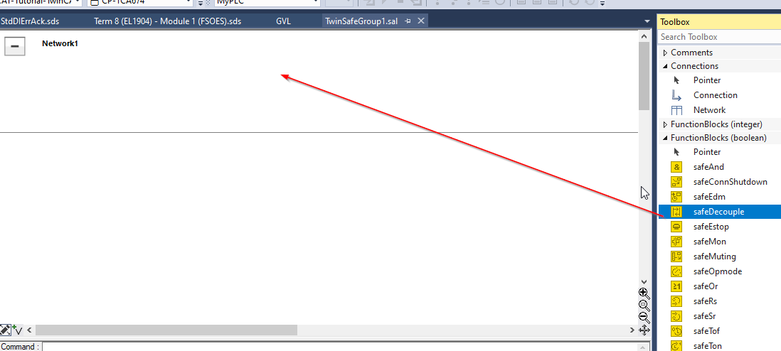
An FBDecouple that uses TwinSafe Connection signals for Group has been added.
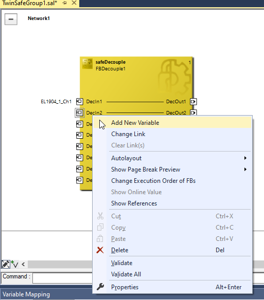
Add New Variable
With DecIn1 selected, right click>Add New Variable.
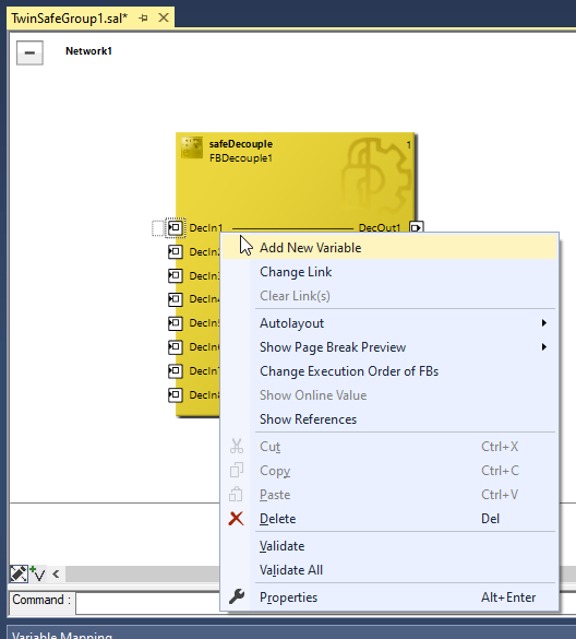
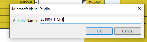
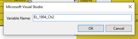
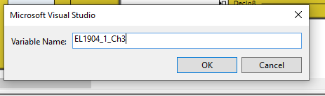
Enter a variable name and press OK.
Let’s add a variable for DecIn2 in the same way.
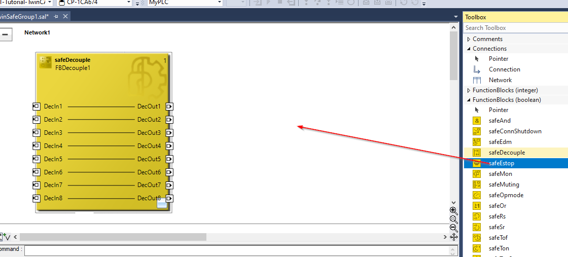
Add Etsop
Add the safeESTOP Function Block to the Safety Program from the Toolbox on the right.
safeESTOP, Intance names were defined in the Block on FBEStop1.
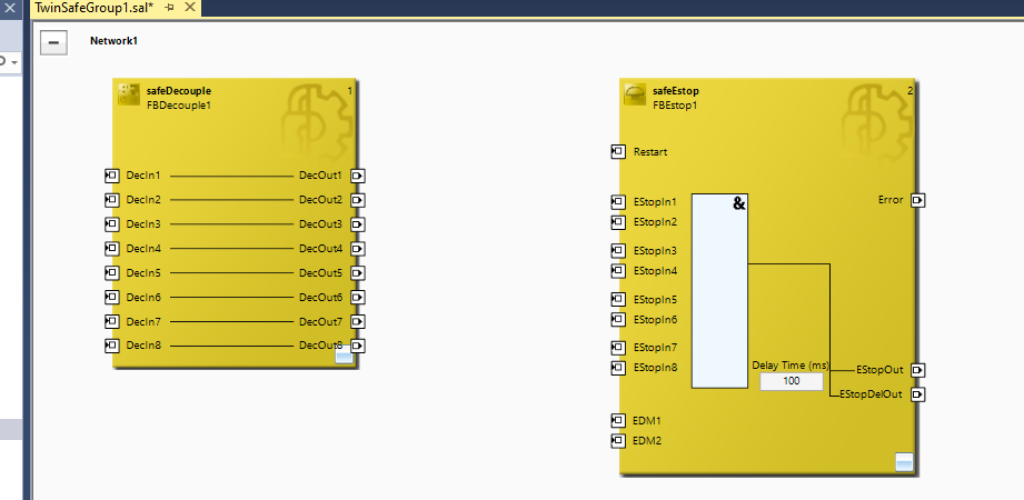
Delay time
You can change the Delaytime directly at Delay Time (ms). In this case, set it to 2000 (ms).
Parameter Setting
Map Diag
You said earlier to define Process IOs for State and Diag in Standard PLC Program and link them to Functon Block in FBEStop, but I don’t see anything in Term5 (EL6910) that could be linked.
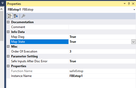
First, I went back to the Safety Program I mentioned earlier and clicked on FBStop, and in Properties there was an Info Data item, in which Map Diag and Map State were set to False.
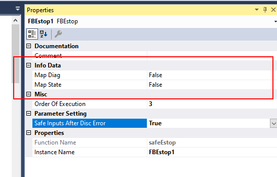
Just by setting those two to True, you can link with the FBEStop information from the EtherCAT EL6910 ahead of time!
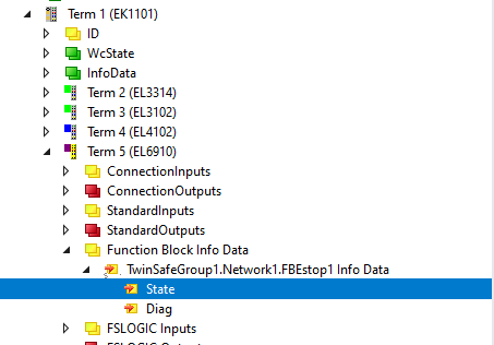
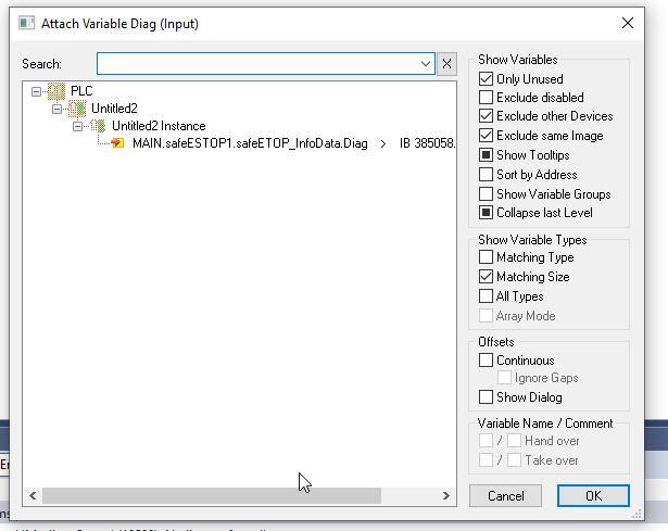
If you check again, do you see a new Input called Function Block Info Data added to TwinCAT? If you expand that Function Block Info Data, you will find State and Diag under TwinSafeGroup.Network1.FBstop1 Info Data.
For your information, the Naming Format of the TwinSafeGroup1.Network1.FBstop1 Info Data is,TwinSafeGroupName. Network.Its Instance name in the Function Block to be diagnosed.
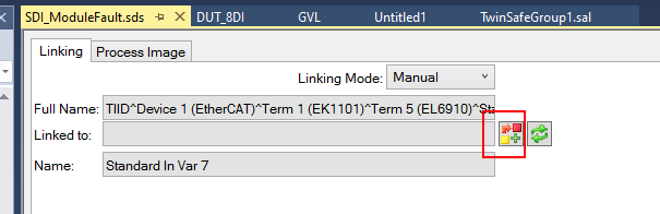
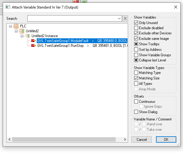
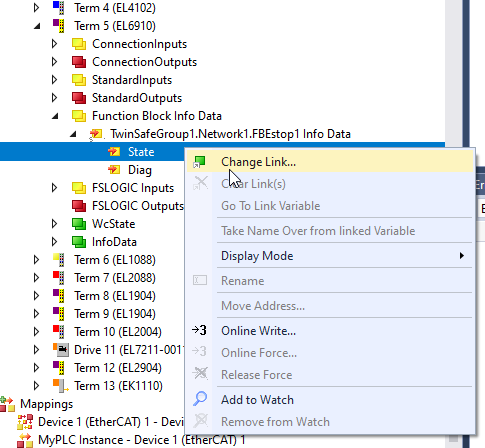
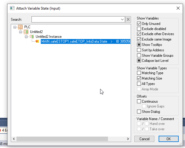
Right-click on State>Change Link and link it to the variable in User Program.
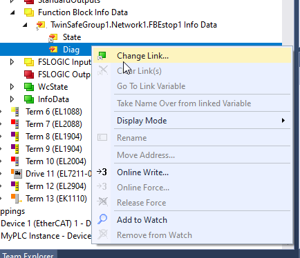
Likewise, right-click on Diag>Change Link and link it to the variable in User Program.
Link to Estop input
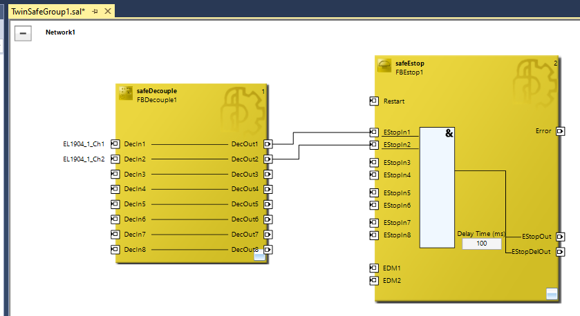
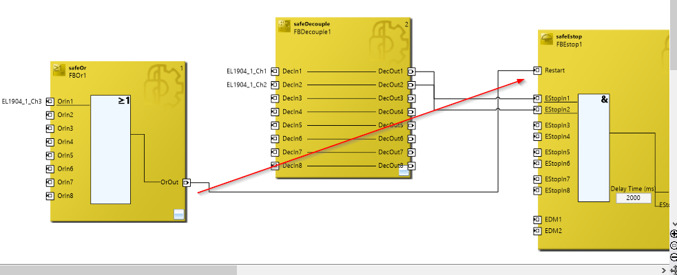
Next, let’s connect safeSTOP’s EStop1 and EStop2 to EL1904’s Channel1 and Channel2, and link the outputs of DecOut1 and DecOut2 to EStopIn1 and EStopIn2.
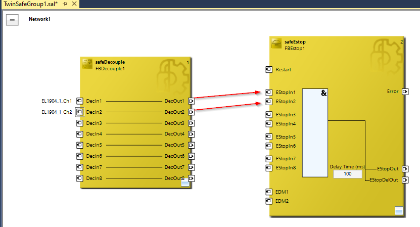
Okay, now the signals from DecOut1 (EL1904_1_Ch1) and DecOut2 (EL1904_1_Ch2) flow into the Function Block of the Estop.
Add ESTOP OUTPUT
Declare output variables for the EStop Function Block: right-click on EStopOut and EStopDelOut>Add New Variable.
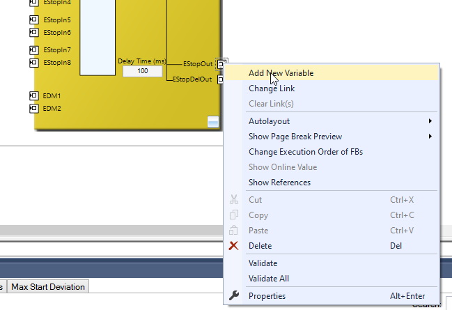
So variable declarations are OK!
Add Reset
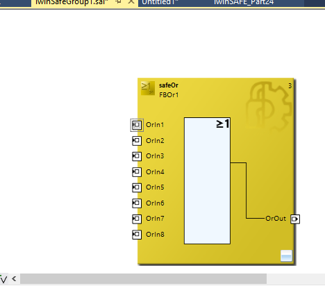
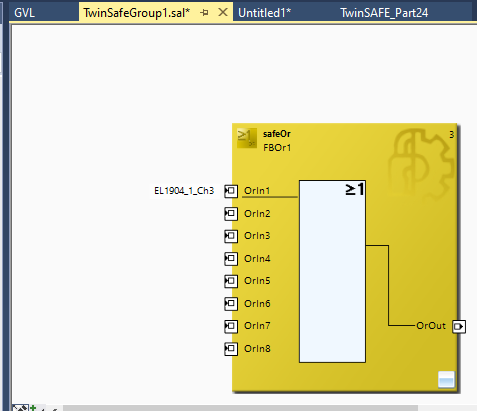
Next we will create a signal to reset the Function Block of ESTOP from the safe state to the normal state. add safeOr on the right side of the Toolbox.

This one is simply the Safety Version of Or Logic, so we are not doing anything too difficult to explain.
Add New Variables
Add a new variable with Add New Variable from OrIn1.
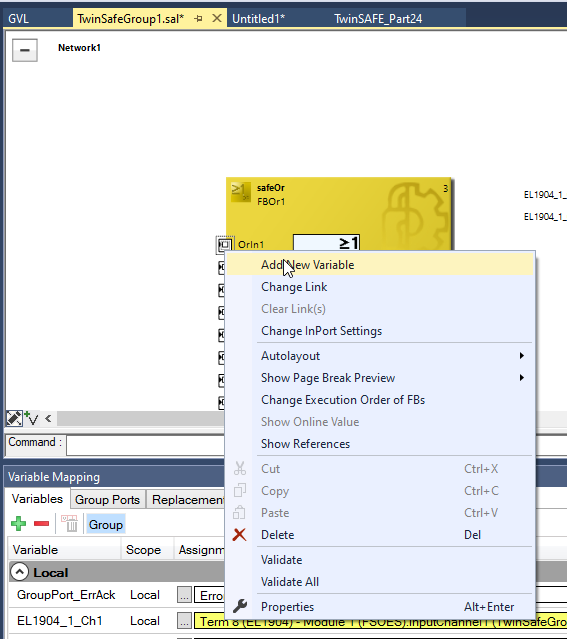
The reset signal is used in Ch3.
Done!
Link to ESTOP Reset
OrOut is connected directly to safetEstop’s Restart input. Now you are ready!
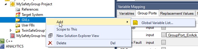
ADD Safety GVL
Now we are going to create a Safety GVL, we add a new Safety GVL at GVLs>Global Variable List.
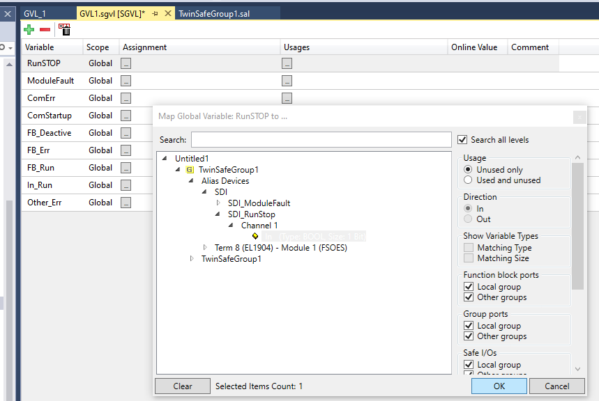
Let’s define a Global variable and link it to the Standard Digital Input and Output that we added first.
Done!
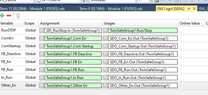
Of course, do not forget to link the ErroAcknowledgement Standard Digital Input to the User program, so that the Function Block cannot be reset.
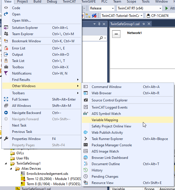
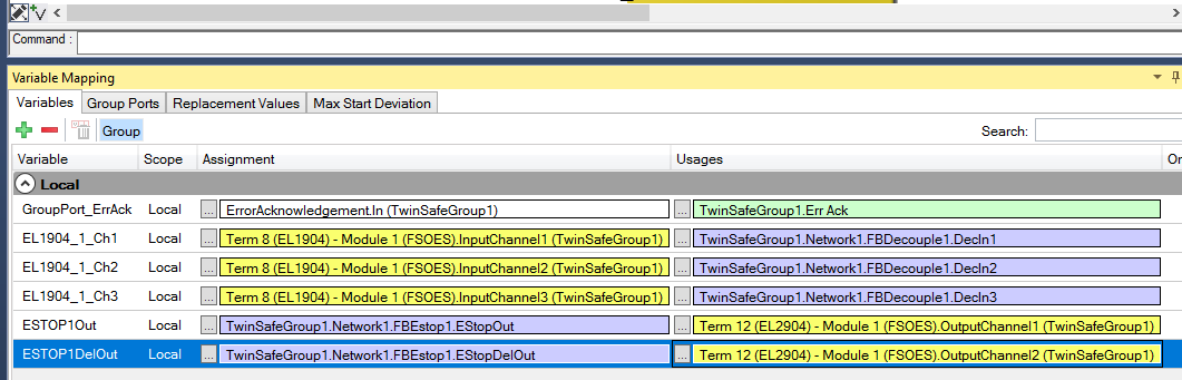
Variable Mapping
View>Other Windows>Visiable Mapping to expand the Mapping screen.
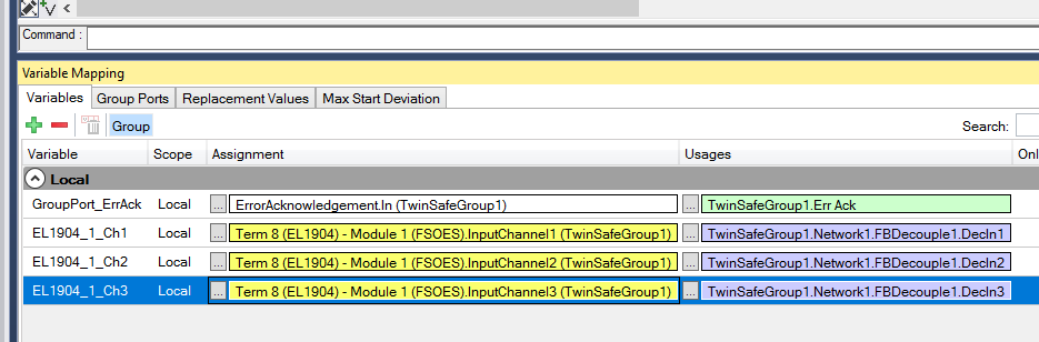
Mapping The Safety Input
Assign the EL1904_1_Ch1/Ch2/Ch3 variables you initially defined to the EL1904 module.
Click … in the Assignment column.
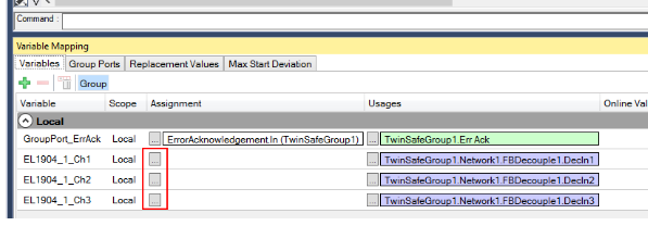
Let’s connect with InputChannel1,2,3 of EL1904.
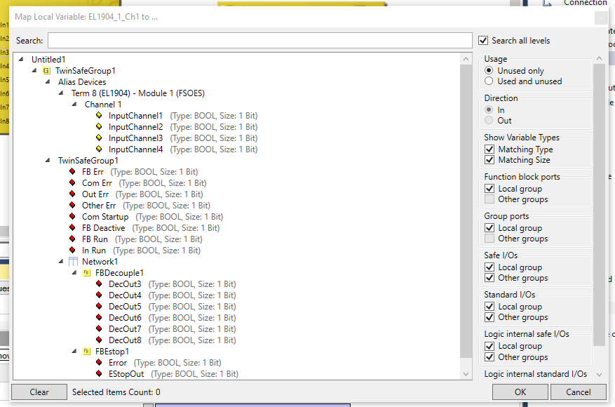
This is OK!
Mapping the Safety Output
The same operation should be used for the FBESTOP output.
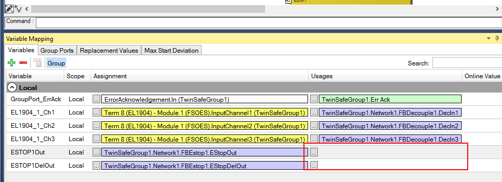
Output Channel 1 and 2 of EL2904 will be used.
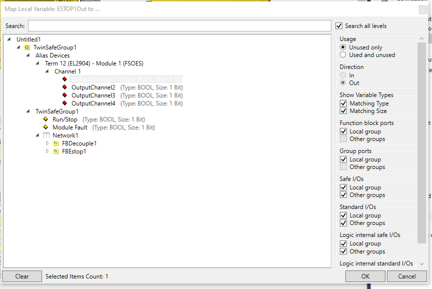
Done!
Warning?
If when you create a Safety program you get a warning like this “A WiredLink connects the Output xx Function Block and xxx which will be executed by logic before…” then TwinCAT is informing you that the program you have created may have a slight execution order problem.
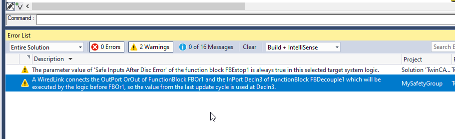
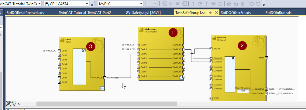
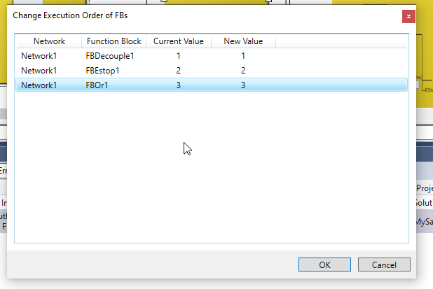
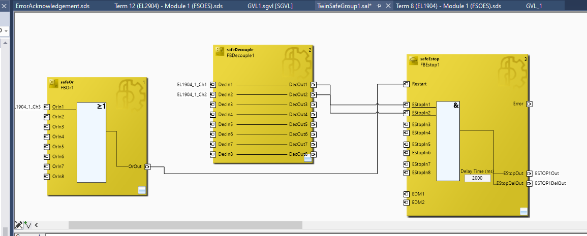
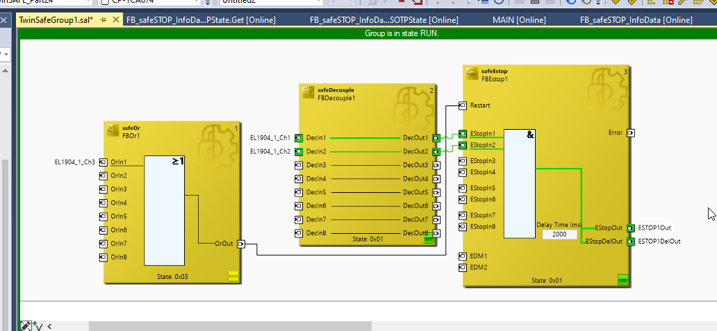
First of all, the order of execution is also indicated by a number in the upper right corner of each Function Block. That number indicates the order of execution of each Block in your TwinSAFE Group.
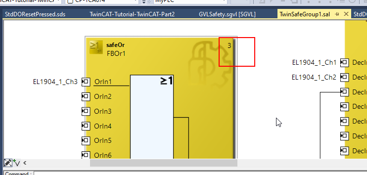
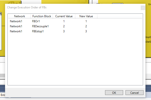
So now the FBDecouple in the middle executes first (1), then the FBEStop (2), and finally SafeOr. It is correct that the order is not correct, that it receives the reset signal from SafeOr (3), then decouples all signals of TwinSAFE Connection, and finally diverts them to FBEStop and other Safety Programs.
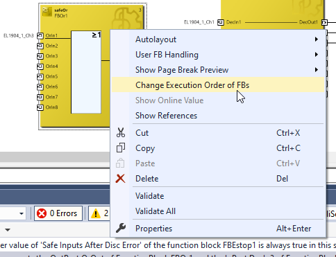
This minor mistake is common and easy to fix: right-click in the white area of the TwinSAFE IDE>Change Executeion Order of FBs.
The Current Vaule and New Value display the current order of execution and the new order of execution to be set.
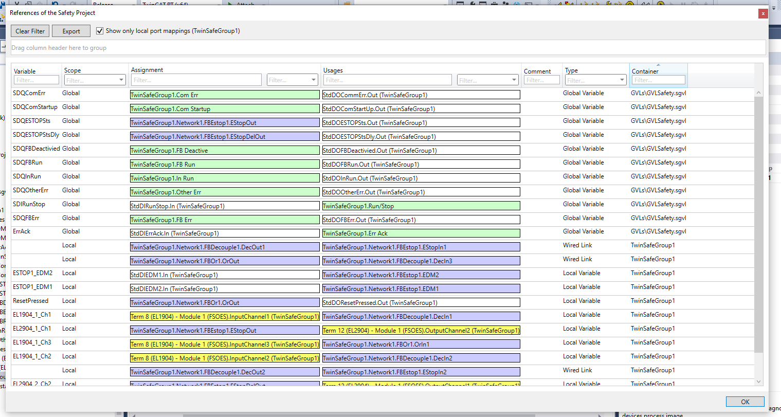
Show Refernce!
Finally, let’s discuss one more Trips. The same function is available by right-clicking on the IDE>Show References.
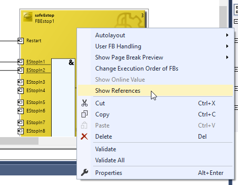
In this way, each variable can be listed in which Function Block it was used.
This is a very useful feature.
Final Flow
Okay, the Safety Program is now complete.
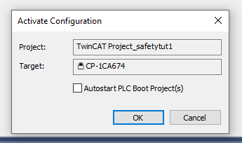
Download Configuration
Download Hardware Configuration first with Activate Configuration.

OK to proceed.
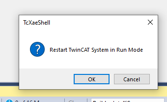
Restart TwinCAT Runtime and switch to Run Mode.
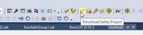
Download Safety Project
Download the safety application at Download Safety Project.
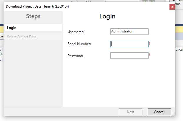
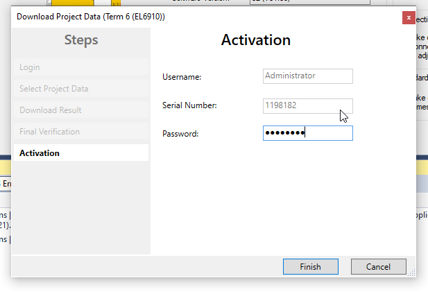
The Login screen will appear, where Username is Administrator.
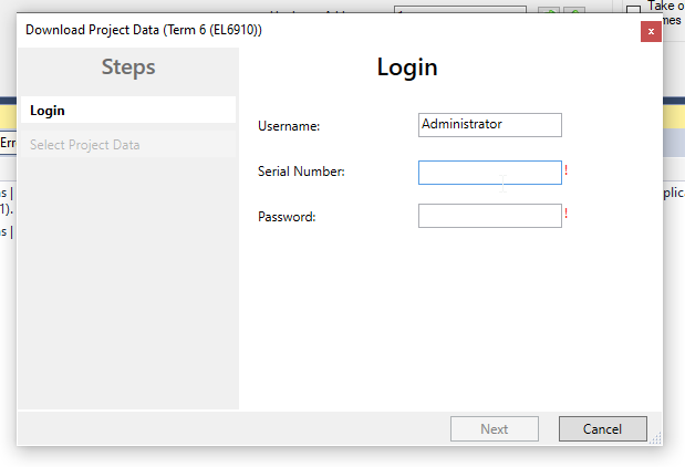
Next is the Serial Number.
Enter the Serial Number displayed on the Target System screen as it is.
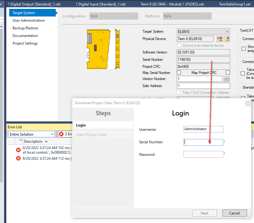
Since this module is 1198182, the Field of Serial Number should be 1198182.
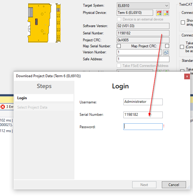
The last Password Default is TwinSAFE.
Enter all of them and click “Next” to proceed.
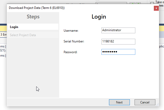
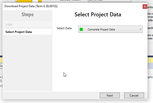
If the information entered is correct, proceed to the Select Project Data screen.
Select Data is Next with Complete Project Data.
The project has been successfully Downloaded and will proceed with Next.
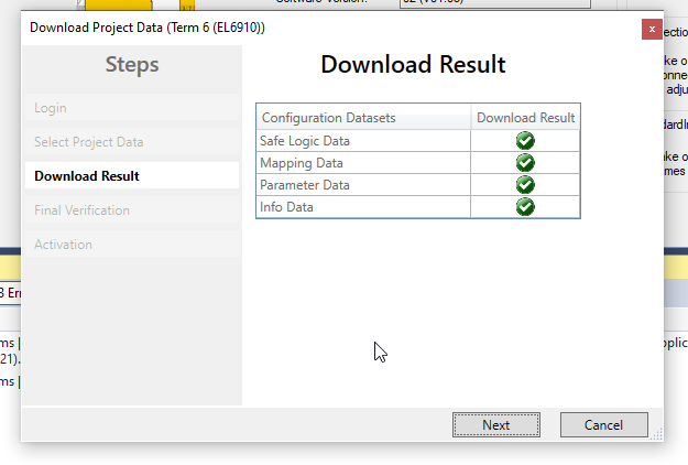
Finally, put Checkbox and Next.
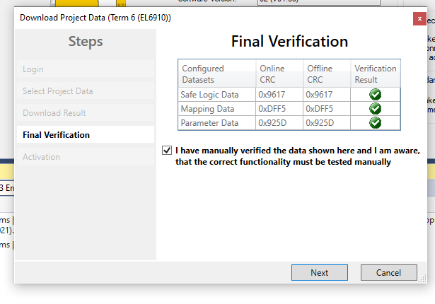
Enter the Password again to activate the Safety Application.
Default Password is TwinSAFE.
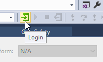
Login
Download the User program to Runtime.
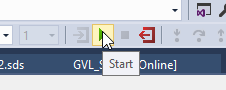
Start
Finally, launch the application and you are done.
Result
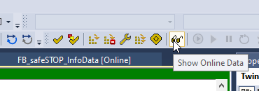
Switch TwinCAT to Monitor Mode from Show Online Data.
I see TwinSAFE Group is working without errors.
You can see the actual movement in this video.
Source Project
Download the Project from the link below.
https://github.com/soup01Threes/TwinCAT3/blob/main/TwinSAFE_Part2.tszip