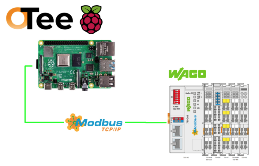
This is a new series of various articles using a Virtual PLC called OTee. In this third article, we will start up the Modbus TCP Client on the OTee Platform and connect it to WAGO’s Modbus TCP Coupler 750-362.
Come on, let’s enjoy FA.
Reference Link
http://soup01.com/en/category/otee_en/
Foreword
Thank you from the bottom of my heart for visiting my technical blog and YouTube channel.
We are currently running the “Takahashi Chris” radio show with Full-san (full@桜 八重 (@fulhause) / X) which I deliver every Wednesday night.
Sharing, not hoarding, technical knowledge
We publish technical information related to factory production technology and control systems for free, through blogs and videos.
With the belief that “knowledge should be accessible to everyone,” we share practical know-how and real-world troubleshooting cases from our own field experience.
The reason we keep it all free is simple: to help reduce the number of people who struggle because they simply didn’t know.
If you’ve ever thought:
- “Will this PLC and device combination actually work?”
- “I’m having trouble with EtherCAT communication—can someone test it?”
- “I want to try this remote I/O, but we don’t have the testing environment in-house…”
Feel free to reach out!If lending equipment or sharing your configuration is possible, we’re happy to verify it and share the results through articles and videos.
(We can keep company/product names anonymous if requested.)
How can you support us?
Currently, our activities are nearly all unpaid, but creating articles and videos takes time and a proper testing environment.If you’d like to support us in continuing and expanding this content, your kind help would mean a lot.
Membership (Support our radio show)
This support plan is designed to enhance radio with Mr Full.
https://note.com/fulhause/membership/join
Amazon Gift List (equipment & books for content production)
Lists equipment and books required for content creation.
https://www.amazon.co.jp/hz/wishlist/ls/H7W3RRD7C5QG?ref_=wl_share
Patreon (Support articles & video creation)
Your small monthly support will help to improve the environment for writing and verifying articles.
https://www.patreon.com/user?u=84249391
Paypal
A little help goes a long way.
https://paypal.me/soup01threes?country.x=JP&locale.x=ja_JP
Just trying to share things that could’ve helped someone—if only they’d known.
Your support helps make knowledge sharing more open and sustainable.
Thank you for being with us.
soup01threes*gmail.com
Technical knowledge shouldn’t be kept to ourselves.
Implementation
WAGO Side
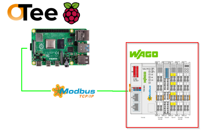
Please refer to this article for WAGO’s Modbus TCP Coupler.
OTee Side
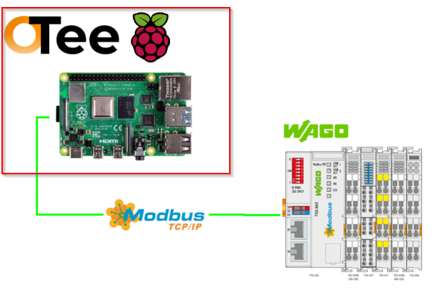
Next, we will build the OTee side.
Modbus TCP Driver Settings
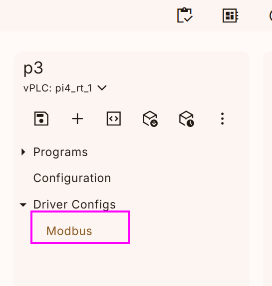
To add the Modbus TCP Driver, click the + button on the left toolbar.
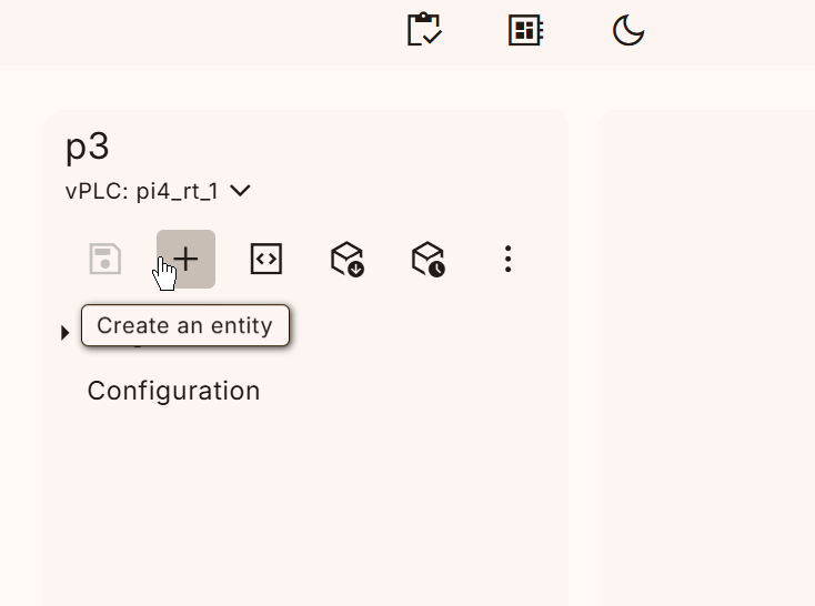
The Add Entity screen will be displayed.
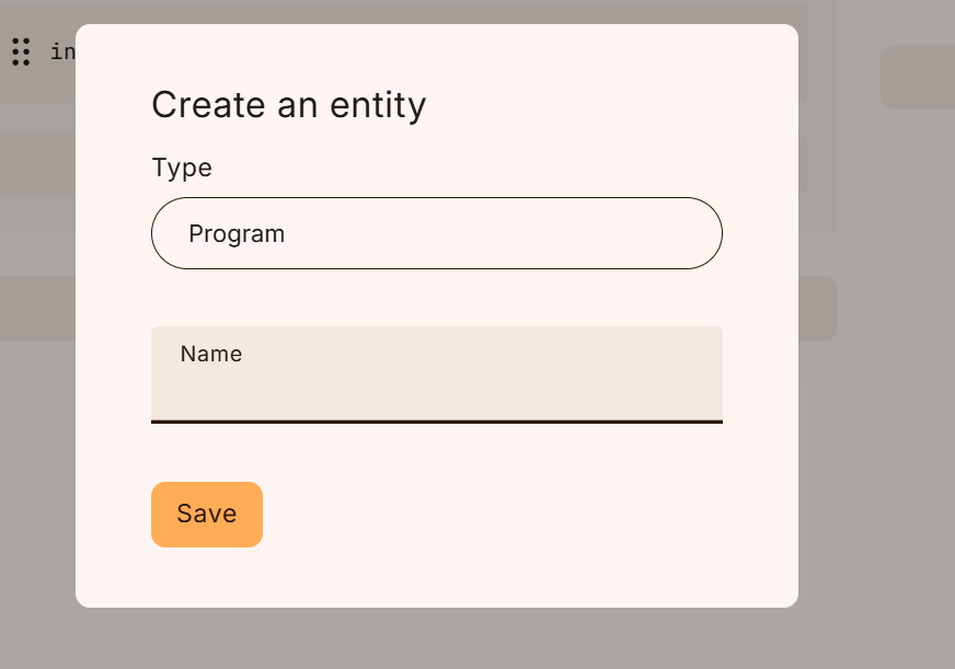
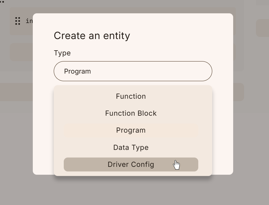
Set “Driver Config” from the drop-down list.
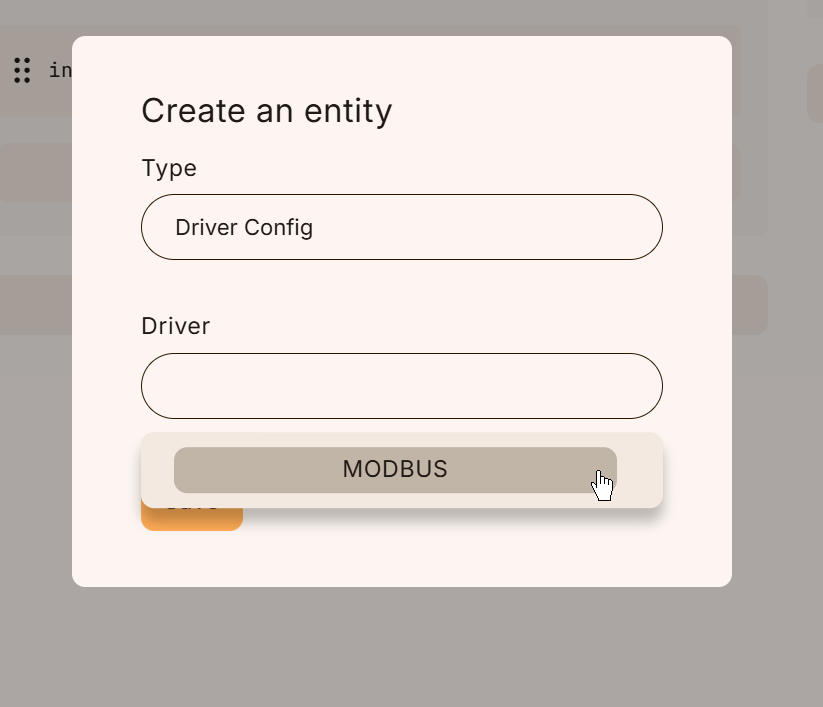
Set the driver to MODBUS.
Save your settings.
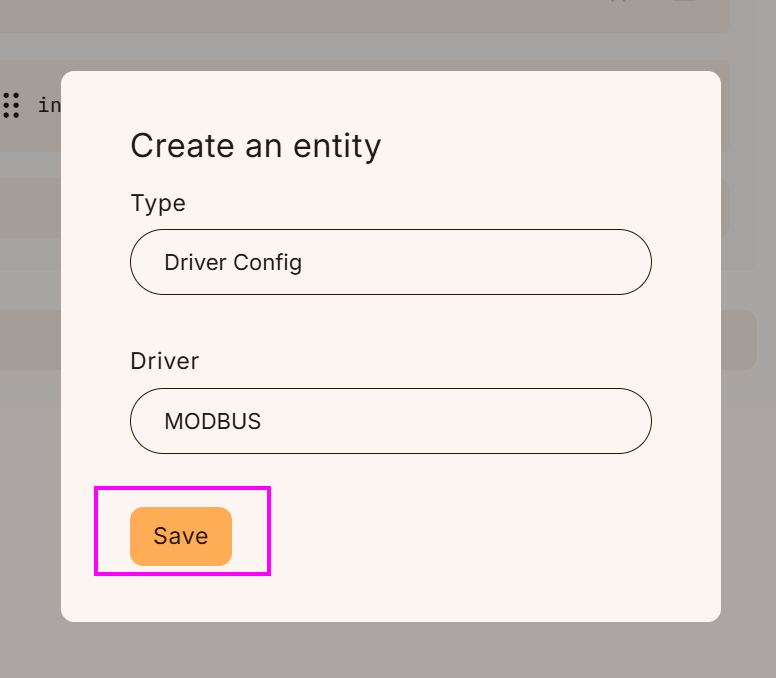
Done!This completes the addition of the Modbus Driver configuration.
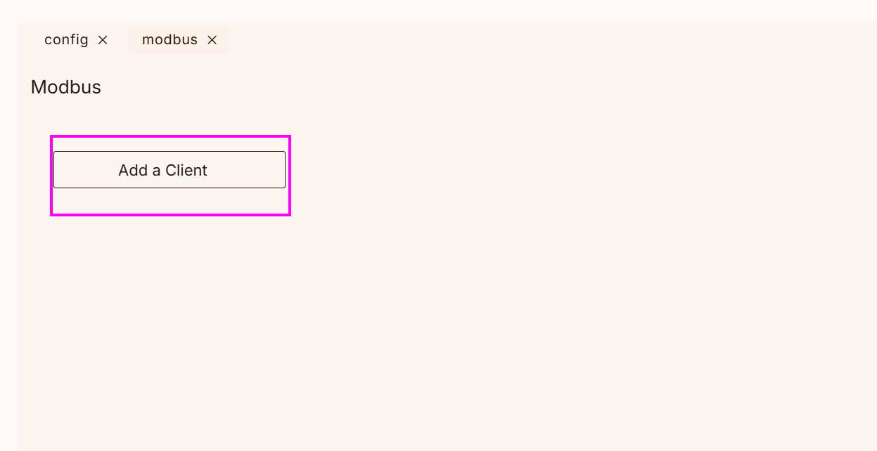
Adding a Modbus TCP client
Open the Modbus Driver you just added and click Add a Client.
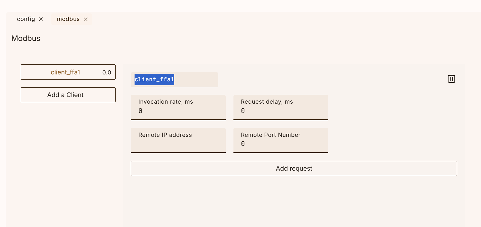
So a new Modbus TCP Client has been added.
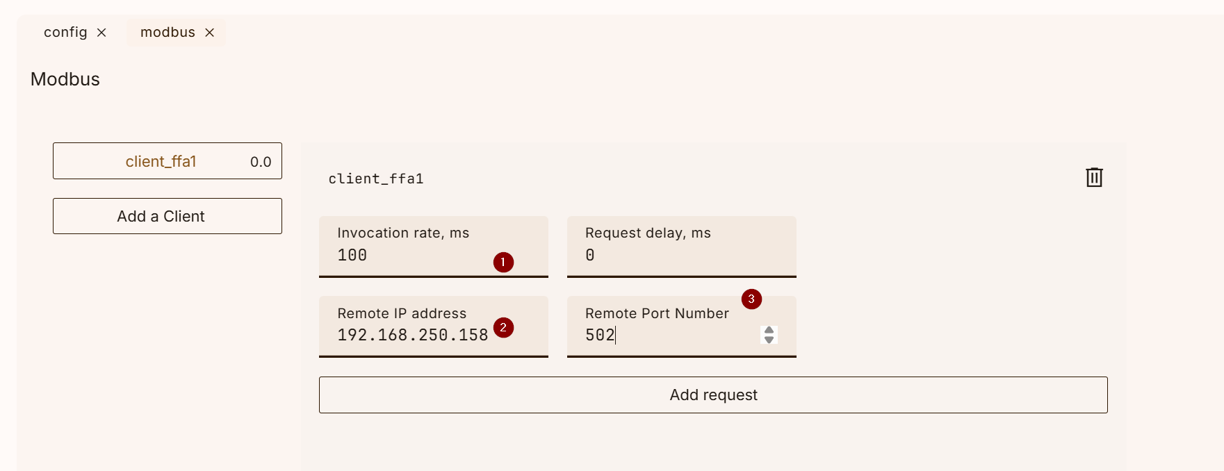
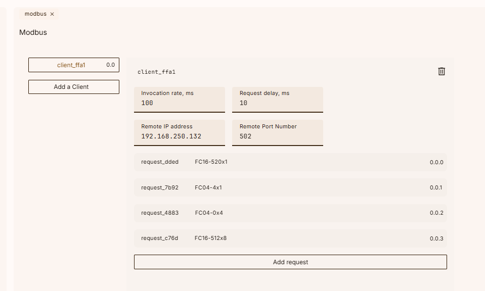
Set the IP address and update cycle of the Modbus TCP Server you want to access OTee Runtime.
Add Request
To add a request to the Modbus Bus Client, click on the “Add request” button
Click on the “Add request” button below to add a request to the Modbus Bus Client.
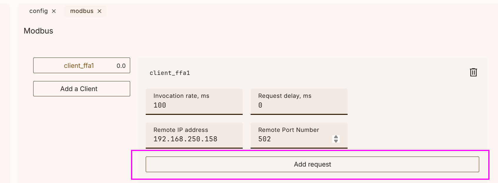
Done!A new request has been added.
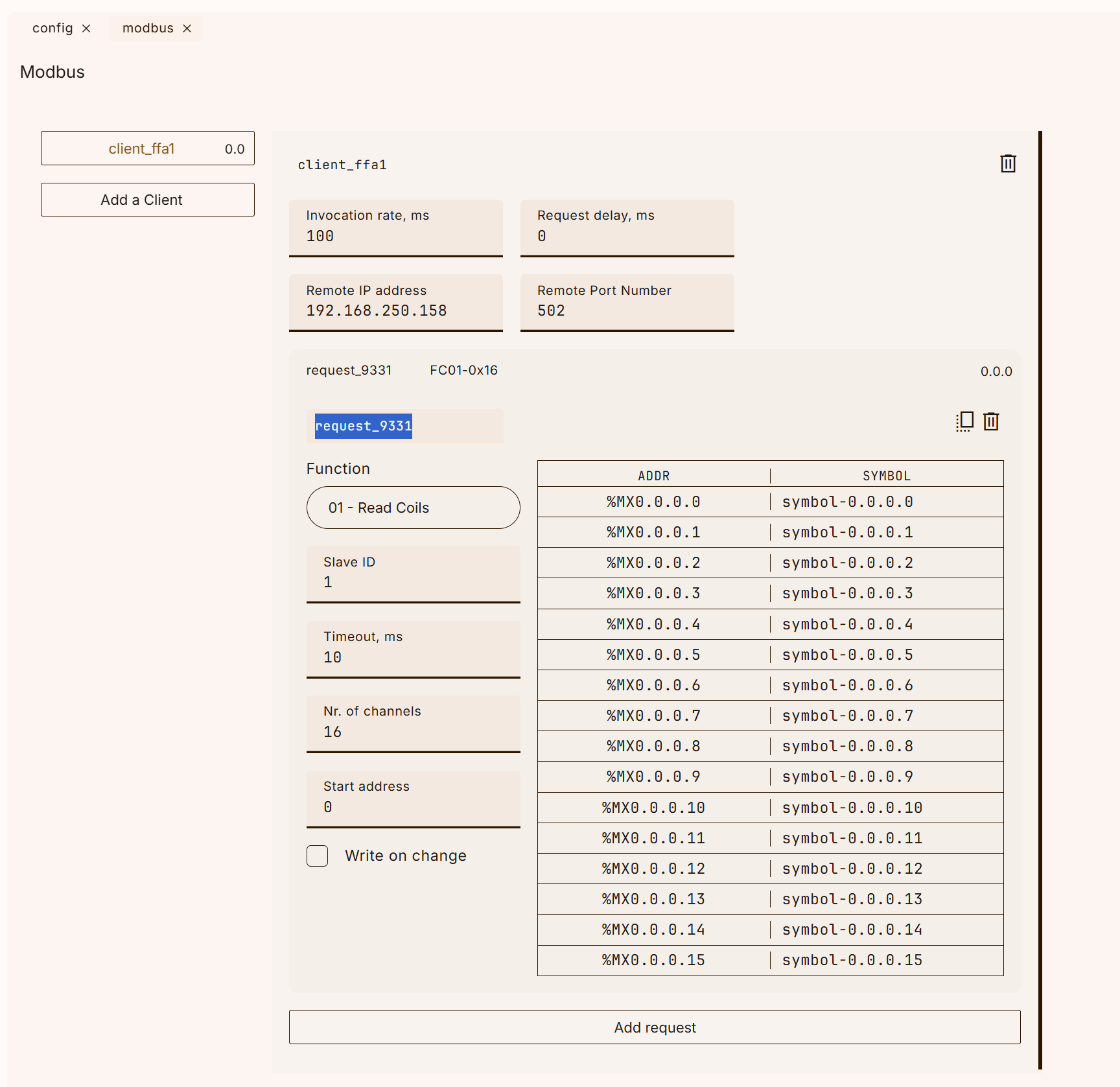
Function
The first step is to set up the FC to access the output module.
You can specify the Modbus TCP FC Code in the Function field.
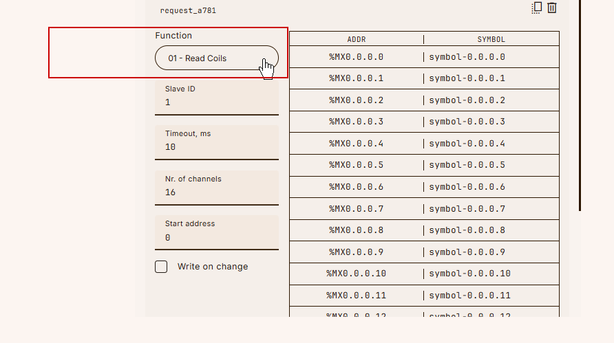
In the Function column, there is a Drop-list, which allows you to set other FCs such as FC01/FC02.
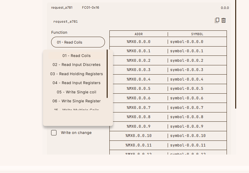
Set FC16 to write the output module in words this time.
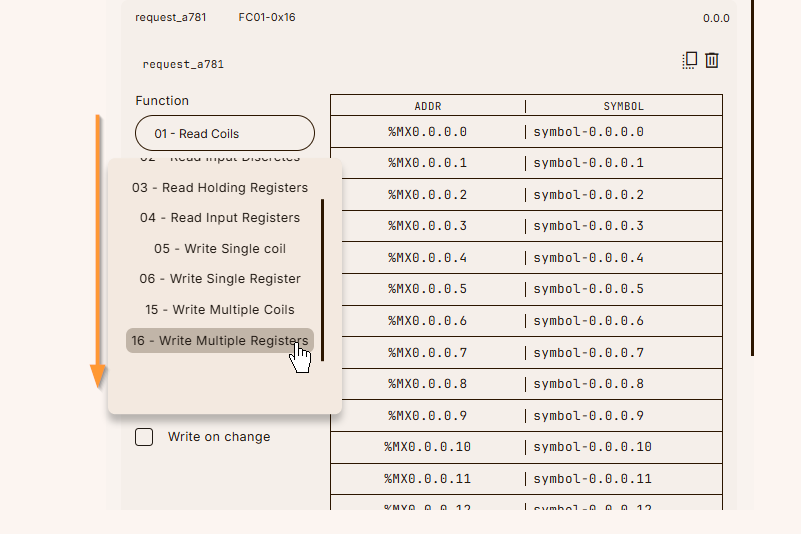
Done!
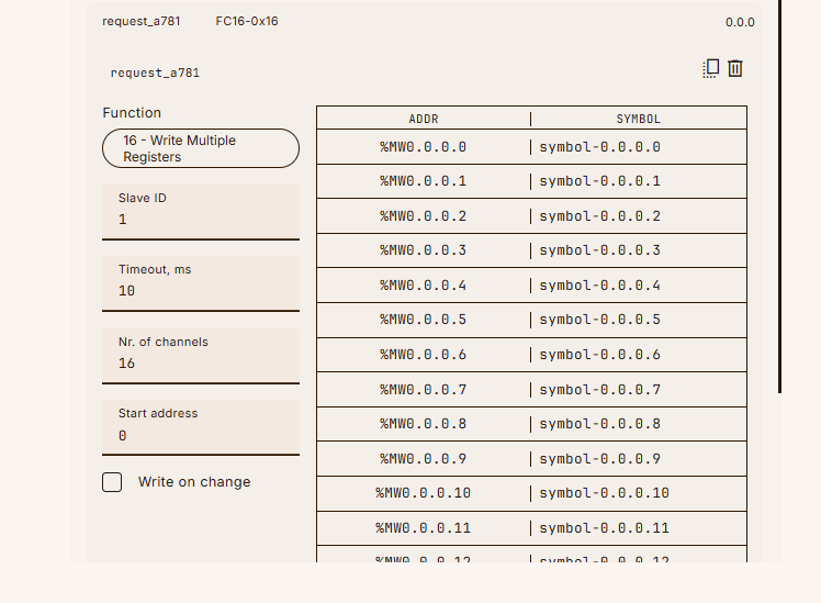
Slave ID
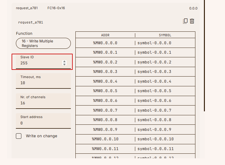
Next, set the Slave ID for the request.
Nr. of Channels
Sets the number of access channels for FC16; on Default, 16 channels are accessed together.
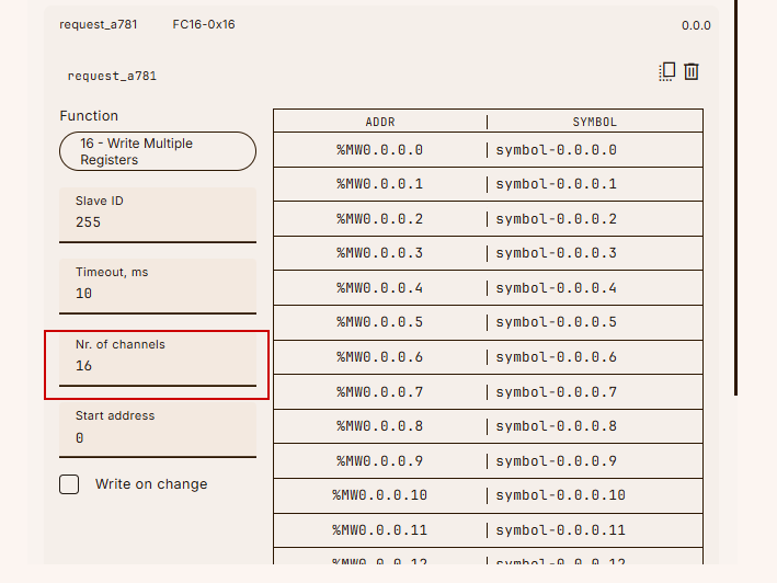
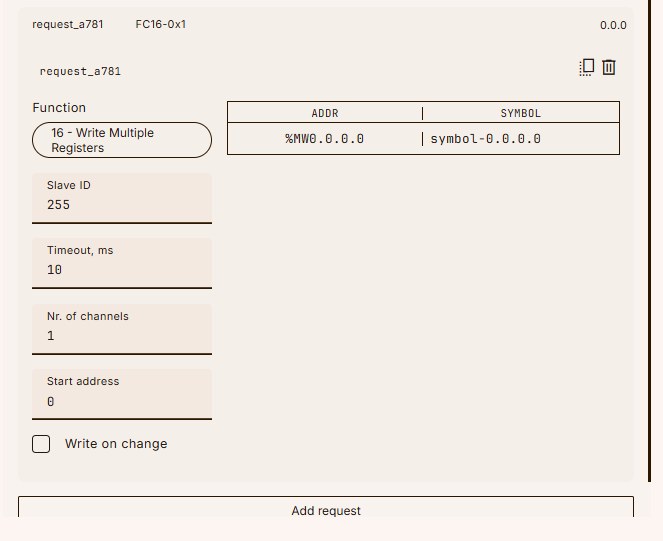
Since there is only one output module in this article, set Nr. of Channels to 1.
Start address
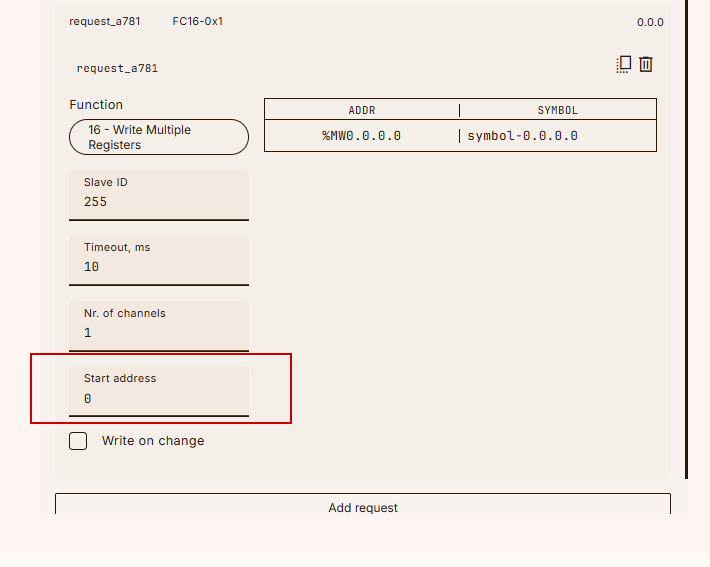
Start Address sets the access register OFFSET for the corresponding request.
In this example, the starting address is set to 520.
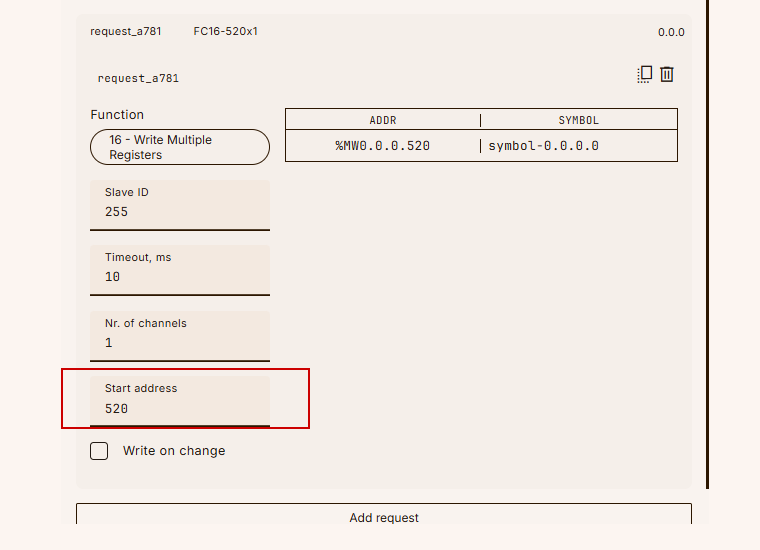
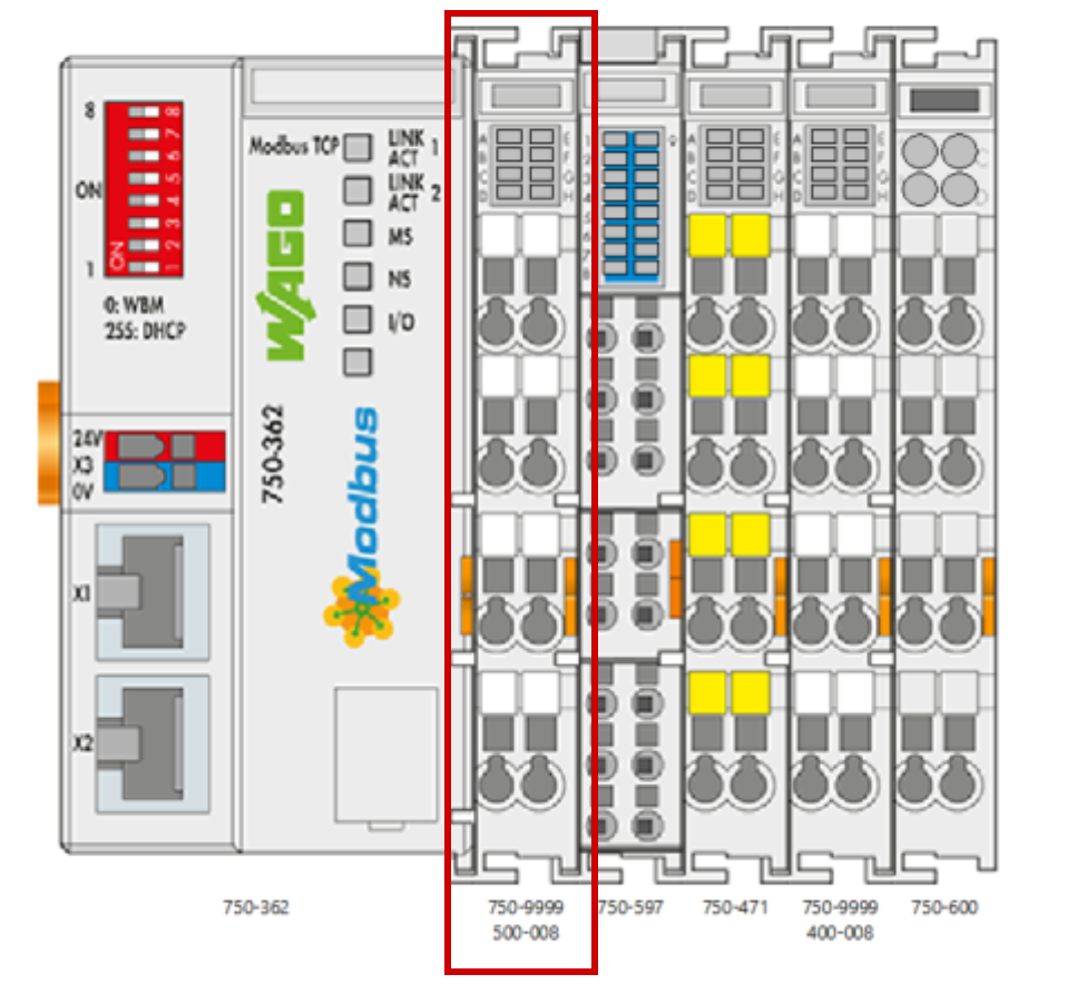
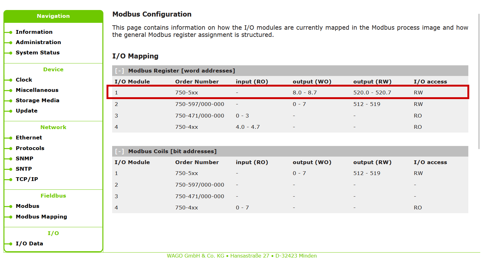
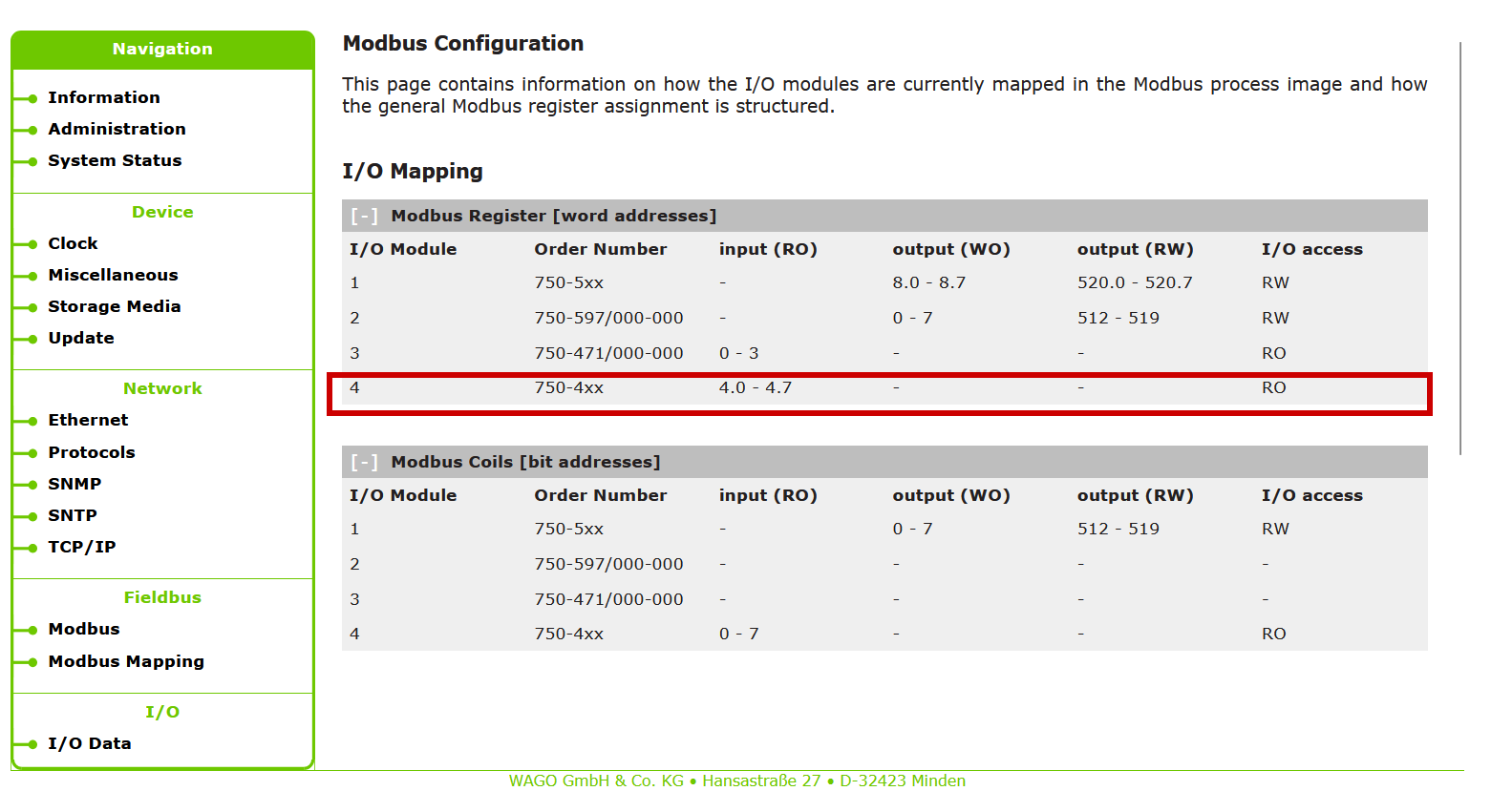
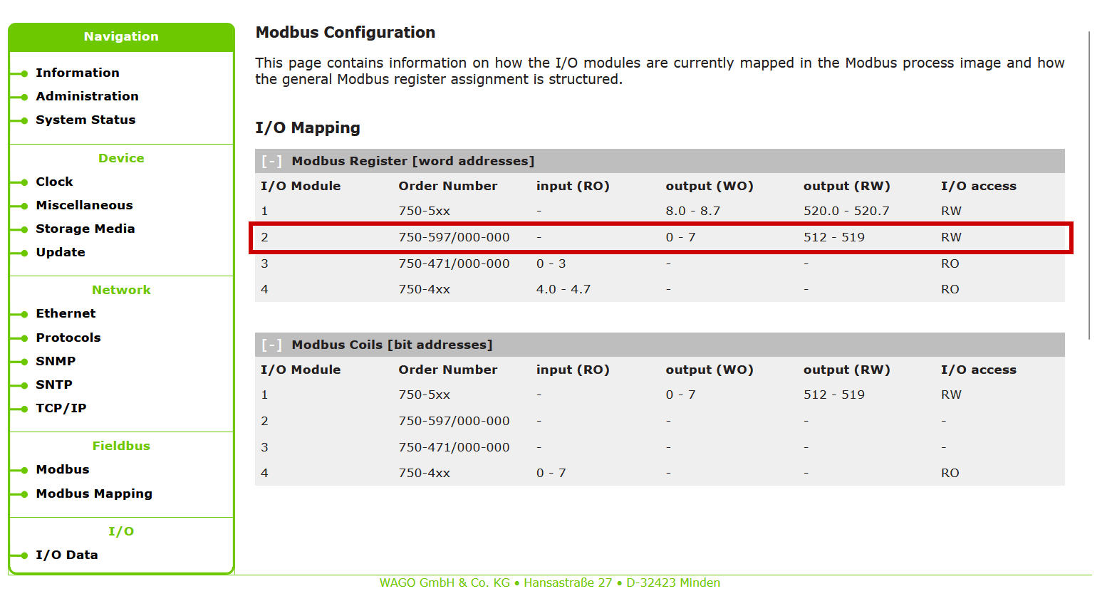
From wago’s Modbus TCP Coupler Web server, we can see that the write register of the output module installed at position 1 has 520 starts.
SYMROL
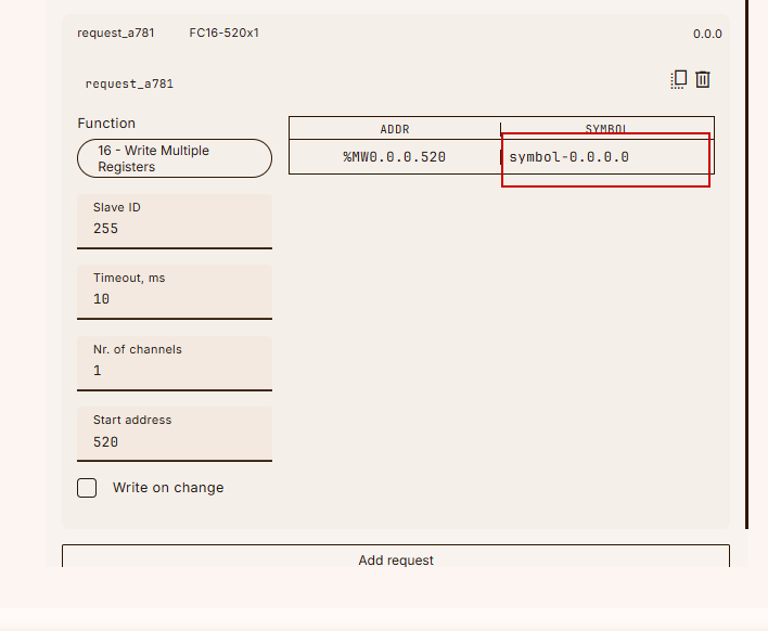
The last step is to set the symbol. The variable is referenced from the symbol to be used in the program, so set an easy-to-understand name.
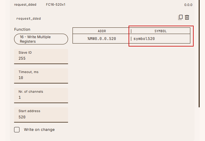
In this example, it is set to symbol520.
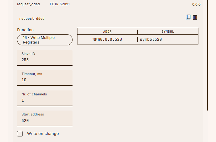
result
This is OK.
Request 2
The next step is to configure access settings for the digital input module installed in position 4.
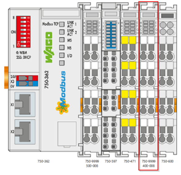
Set start address = 4.
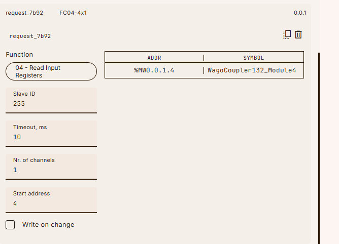
I can confirm with wago’s modbus tcp coupler that its address is 4.0.
Request 3
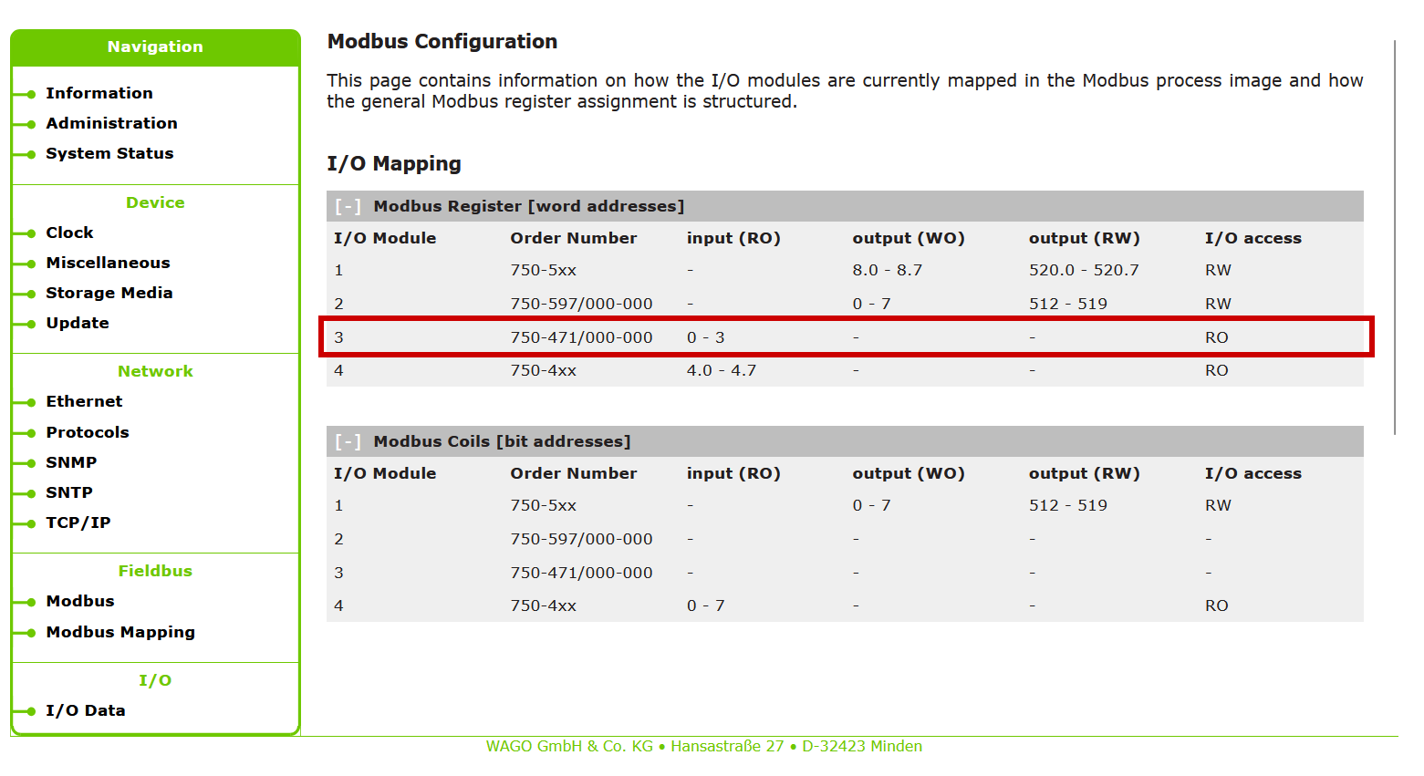
The next step is to configure access settings for the analog input module installed in position 3.
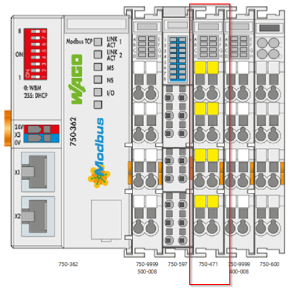
Set start address = 0 and channel = 4.
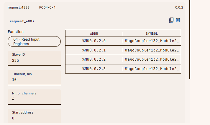
You can verify that address is 0 with wago’s modbus tcp coupler.
Request 4
The last step is to configure access settings for the analog outputs installed in position 2.
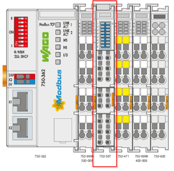
スタートアドレス=512、アクセスレジスタ数を8に設定します。
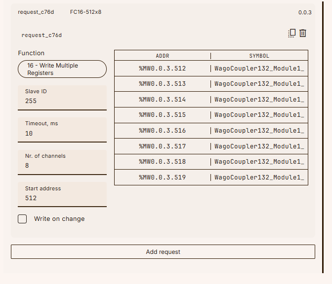
その設定はwago modbus tcp coupler上で確認できます。
result
Done!This completes the register access settings for the four modules installed in the Wago Modbus TCP Coupler as well.
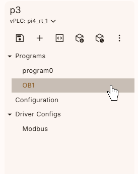
Program
The next step is to create a program.
Mapping
Define variables to read and write to the Wago Modbus TCP Coupler.
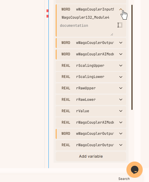
Next, Mapping the variable to the actual Modbus TCP Coupler. Expand the variable you just defined and click on the empty space.

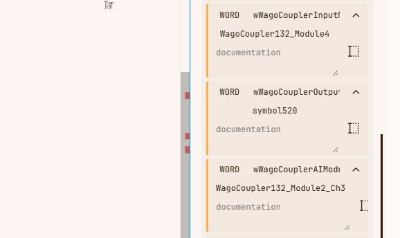
A list of Modbus TCP variables that we have defined will be displayed, and we can map the appropriate Symbols to them.
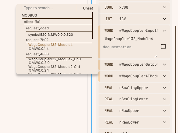
Done!
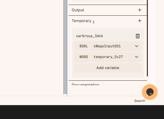
Finally, temporary variables are also defined in the Temp area.
VAR
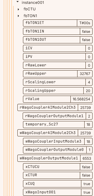
This is the variable defined in this article.
Code
Here is the code we created for this article.
- Scales the current input acquired from the analog input module.
- Scaling and outputting the set value to the analog output module
- Control digital inputs and outputs
|
rScalingUpper:=20.0; rWagoCouplerAIModule2Ch3:=WORD_TO_REAL(IN := (wWagoCouplerAIModule2Ch3)); rValue:= ((rWagoCouplerAIModule2Ch3-rRawLower)* fbTON1( xWagoInput001:=WORD_TO_BOOL( temporary_5c27:=wWagoCouplerInputModule3; if xWagoInput001 then wWagoCouplerOutputModule1 := REAL_TO_WORD( fbCTU( |
|---|
Download
最後はプロジェクトをRuntimeにDownloadしてください。
result
You can check the operation from this video.