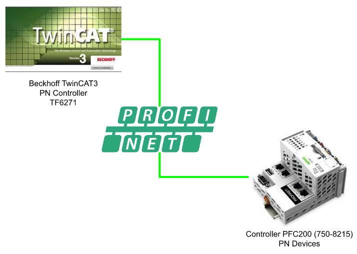
In this tutorial I will show you how to use Beckhoff TwinCAT TF6271 to start up a Profinet Controller and build a profinet communication with Wago PFC200(720-8215) Controller.
Let’s Start!

Video
English Version
Japanese Version
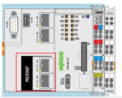
Interface
There are 5 ports in Wago 750-8215.As see belowe X1,X2,X11,X12 and one internal port inside the CPU.We can configure these ports as:
- 1 IP address share with 4 ports
- 2 IP addresses with 2 networks, each network with 2 ports.
- 2 IP addresses with 2 networks, 1 network with 3 ports.
- 4 IP addresses with 4 networks, each network with 1 port.
And we can configure it by the web server.
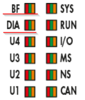
LED
There are 2 LEDs on the CPU for Profinet display.
BF=Bus fault,DIA=had Profinet diagnostic message
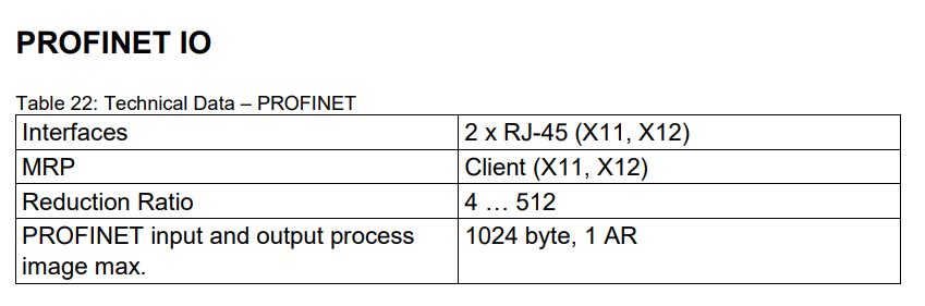
Technical Data
Network Structure
Here is the structure of the CPU ports. Seperate the Commissioning network and Profinet network is recommended, It is better to use X1,X2 for the commissioning port and X11,X12 for the Profinet network.

MAC ID And IP Assignment
Now we can access the web server and start to set the ethernet configuration.
Ethernet Configuration
Go to Networking>Ethernet Configuration and click the Configuration.

The Bridge setting of the ports can be configured in here, and please press Submit button to save it.

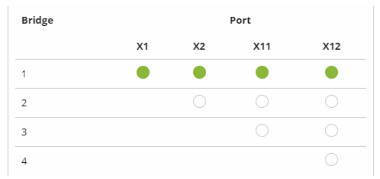
Configuration1
In this setting, X1,X2,X11 and X12 are configured as the same Bridge – It means that 4 ports are sharing one IP address.
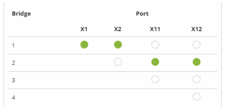
Configuration2
In this setting, X1,X2 as Bridge1 and X11,X12 as Bridge2.
It means that X1,X1 had one IP address but X11,X12 also had one more.
Configuration3<Using in this Profinet>
In this setting,X1=Bridge1, X2=Bridge2, X11 and X12=Bridge3.It means that X1,X2 had their own IP address , and X11, X12 are sharing an IP address.

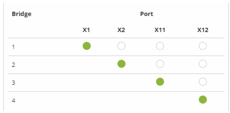
Configuration4
Here is the Configuration that each port had their own IP address.
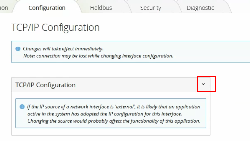
TCP/IP Configuration
Now we can configure the Ip address.
Go to Networking>TCP/IP Configuration>Configuration.

Press this button to expand the TCP/IP Configuration Setting Field.
br0,br1,b2 can configure the ip address separately.
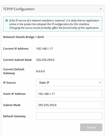
The Bridge setting will be overwritten if the profinet interface is configured.

Implementation
Configuration
Here is the configuration in this tutorial.TF6271 Profinet Controller RT is used in the beckhoff side, and Profinet Device is configured in the wago side to implement a profinet real-time communication.
Wago Side
Let’s start from the wago side first.
Interface
Here is the bridge setting. X1,X2 have their own IP address and X11, X12 will share the same IP address.Please use X1,X2 to download the project from E!COCKPIT.
Configure The PN-Controller
Open the E!COCKPIT and go to the network view.
Search “Profinet” in the Product Catalog side and Select Generic_PROFINET_Controller, Drop in the network.
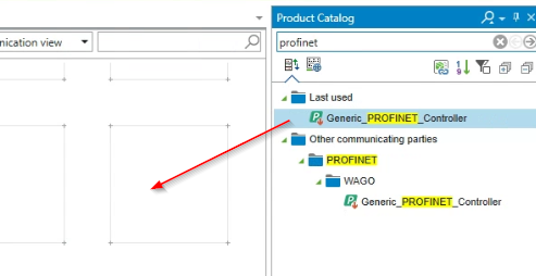
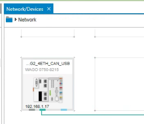
PROFINET Controller is inserted in your project.
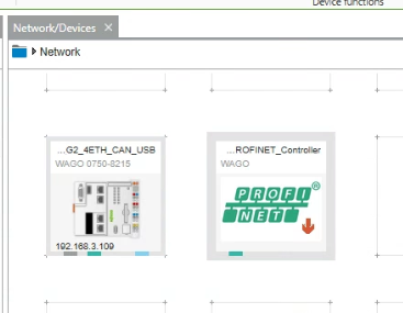
Connect the Profinet Controller to Wago CPU.

As you see the profinet network is started up.

The operation is just like below.
Create the Mapping
Now we can start to configure the I/O mapping.
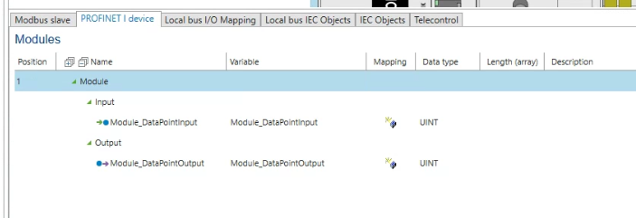
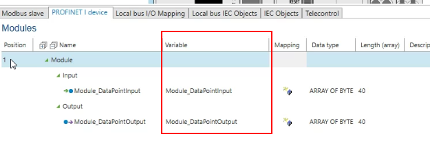
Double click the CPU and open the PROFINET I device tab.

Right click>press the add button to create the new profinet variable.

Input and output are both automatically created.This is the Io data that actually exchange with the Io controller.
You can also change the data type of that variable.
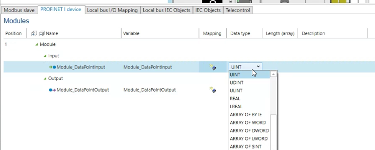
Array is used in my tutorial and after you configure the Io variables as array, the length of that variable can be set in Length(array).
Enter 40 in here.

You can also change the variable name and it will be used in the user program..
Export GSDML
GSDML file is necessary to configure the profinet network.Go to NETWORK FUNCTIONS and check the PROFINET I DEVICE tab.
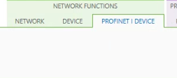
Click the Export button.

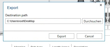
Configure theExport path and “Export”.
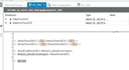
Program
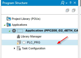
Now we can create the Test program. Go to “Program Structure”.

Click the PLC_RPG.
Define the Byte Array in the VAR field and use it in the user program.
Codesys will not update the variable if not used in the user program.

Download
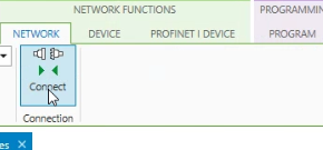
Finally Go to NETWORK FUNCTIONS>NETWORK and click Connect to Download the Project to CPU.
LED Status
BF and DIA are in red now.

TwinCAT3 Side
Now we can configure the TwinCAT side.
Add PN Controller
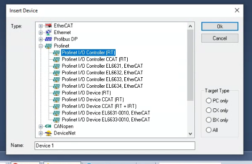
Start the TwinCAT3 Ide> Create the new project>I/O Device>Right click and Add New item.

Select Profinet I/O Controller(RT) and OK.
Choose the Ethernet interface that is connected in the Profinet network and Choose OK.

Profinet Controller is inserted.

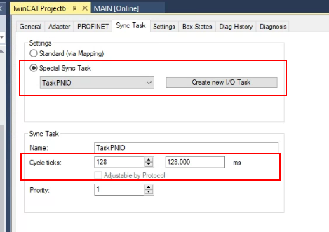
Sync Task
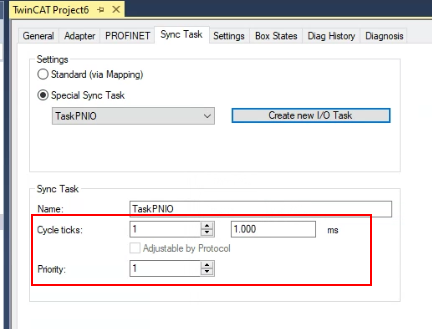
Open the Sync Task and select “Special Sync Task”>, Create new I/O Task to create a Task for profinet.

Enter your Task name,OK.

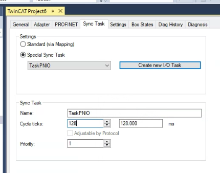
Please make sure the Cycle ticks are based on 2(1,2,4,8,16,32..).
An USB to LAN Adapter is used in my system, longer cycle is set in my project – 128ms.
PN Controller IP
Open the Settings Tab to Configure the IP > press “Set IP settings”.
Please be careful that this IP address is not the same as your Ethernet interface.

Adapter
Please double check if the Ethernet Interface is correct or not.

Add PN Devices
Now we can insert the Wago PN Devices in our profinet network.
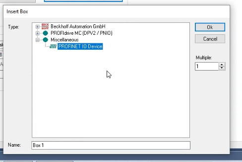
Right click the PN Controller that was inserted in the previous step>Add New Item.

Go to Miscellaneous and Select PROFINET IO Devices>Ok.
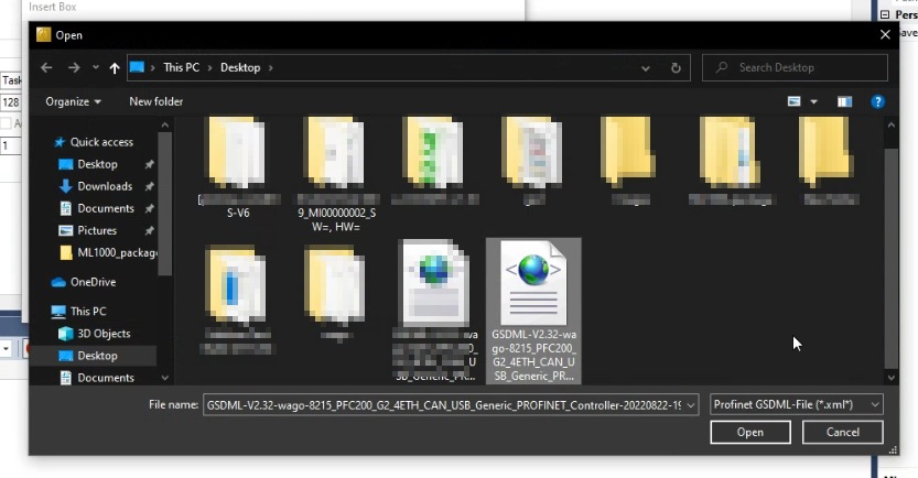
Choose the GSDML that exported from E!COCKPIT>Open.
Wago Profinet Devices is inserted.

Configure- Legacy config
Please check the “Legacy config” if your TwinCAT Runtime version is lower than 4024.
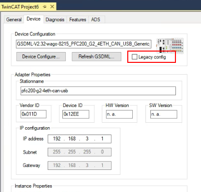
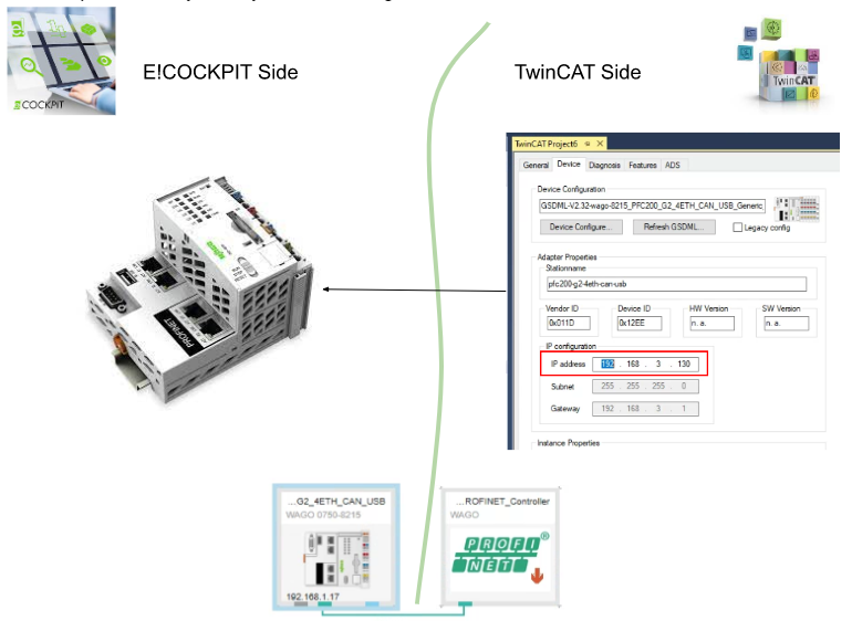
Configure – IP
Please set the PN Devices ‘s IP. Because Profinet Controller will auto assign the ip for each PN Device while startup.

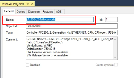
Configure-Device name
Go to General Tab and Change the Name field , this is the field of your profinet device name.(In my case, it is Wago 750-8215)Profinet will assign the IP to that device, based on this device name.
Configure-Mapping
Now we can configure the Variable Mapping.

Add PLC
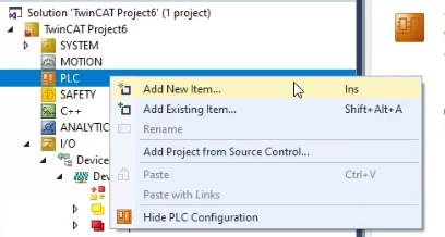
Go to PLC > Right Click >Add New Item.
MAIN
Define the Bytes array variables as Process IO and use it in your user program.
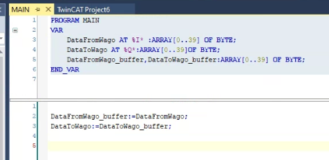
Build
Go to Build>Build Solution to compile your project.

Link the Variables
Finally you need to link these variables inside your user program to the Profinet.
Inputs
Click the Inputs object.

Use Ctrl+A to select all the process input>Right Click >Change MultiLink.

Select the process Input that is defined in the user program>OK.
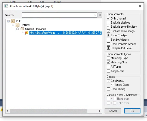
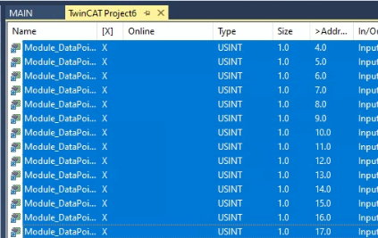
[X] mark is shown if that variable is assigned.
Outputs
Click the Outputs object.
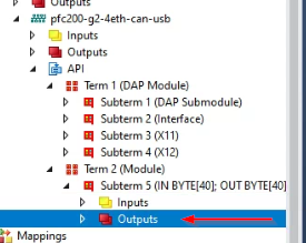
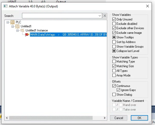
Use Ctrl+A to select all the process Output>Right Click >Change MultiLink.
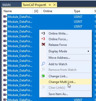
Select the process Output that is defined in the user program>OK.
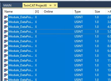
[X] mark is shown if that variable is assigned.
Download
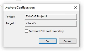
Press the Activate Configuration button to download the hardware configuration to the TwinCAT Runtime.

OK.
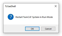
Restart the TwinCAT Runtime.
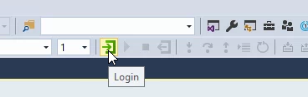
Press Login to Download the user program.
YES.

Press start to start your Runtime.

Summary
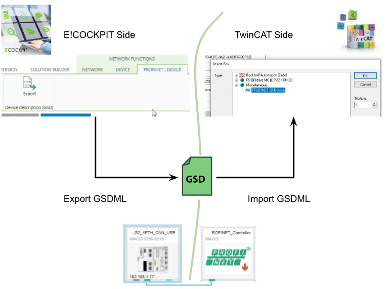
GSD
The GSDML file is exported from E!COCKPIT , and import to TwinCAT IDE.
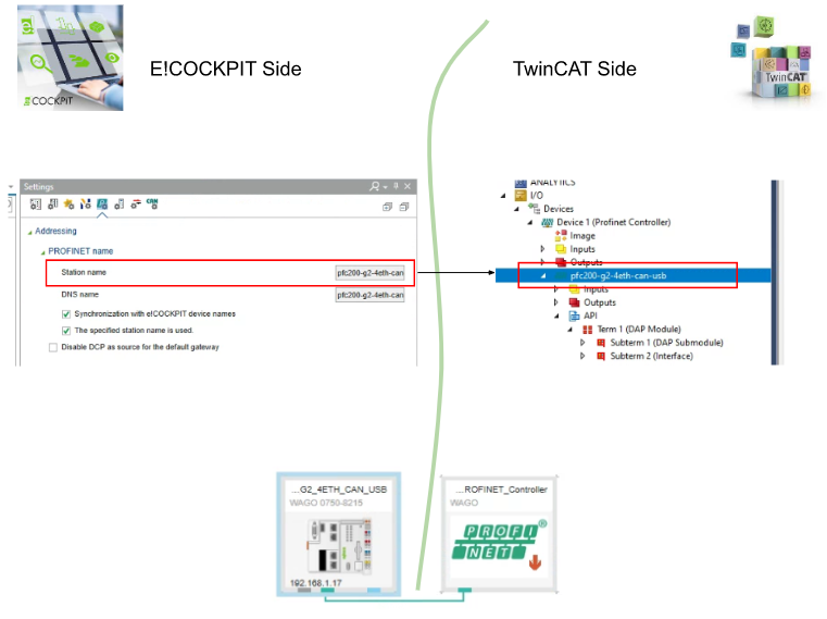
Device Name
Device Name is the most important item in the profinet, we can configure it in E!COCKPIT side.Then we need to match it in the TwinCAT Side.
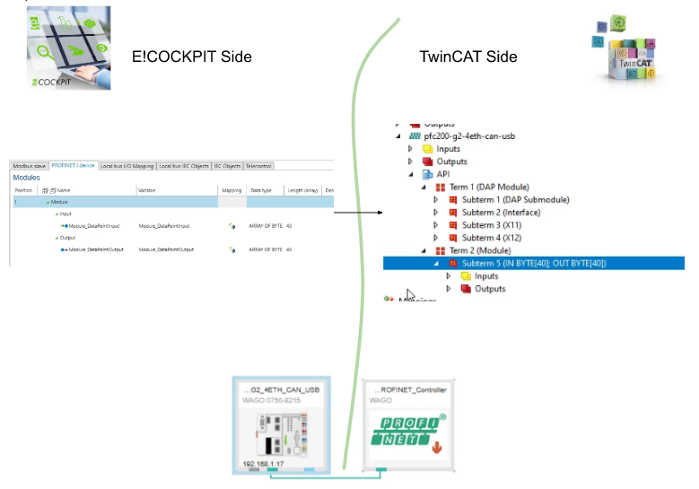
Mapping
The Wago 750-2815 Profinet variables are configured in the E!COCKPIT Profinet i-Device Tab.And this mapping will be imported in TwinCAT Automatically while the GSDML file is imported.
IP
For the Ip address , you only need to configure it in the TwinCAT Side.\
Result
Now we can check the Communication status. Double click the TwinCAT3 Profinet Controller.

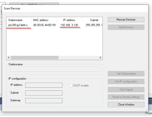
Open the PROFINET Tab and click the “Scan PNIO Devices” Button.
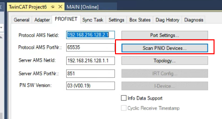
Please wait for twincat to finish the scan..
This tool is not only for searching the profinet devices in the network but also can set the device ip/ip address ,etc.
As you see below,plc200-xxx is the device name of your wago plc and the on controller (twincat)automatically assigns the ip address to it -base on the configuration.
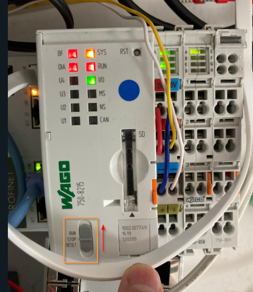
Turn it to Run
finally we can change the CPU status to run by using the button.
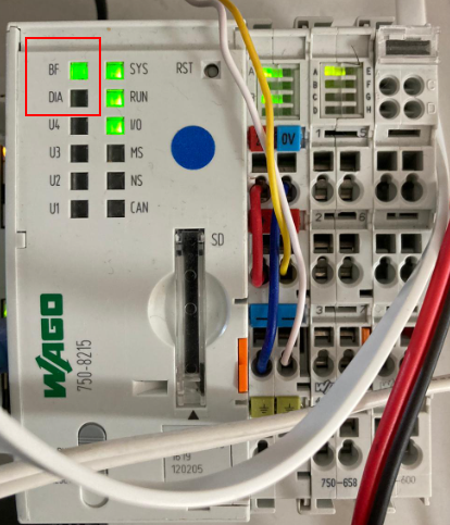
If the profinet network is normal , the BF LED is green and DIA LED is off.
Check in Wago Side
Let’s check the condition on the wago side first.
Open the E!COCKPIT and you can check the Profinet status – now it is running and with a green LED.

Check in TwinCAT3 Side
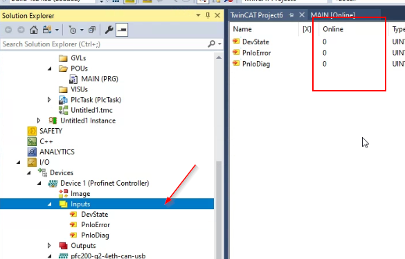
We can also check in the twincat side by PN controller > Inputs , 0=no error in the Profinet controller side.
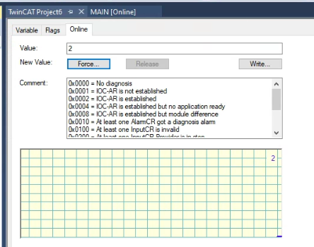
And we check the profinet status between the wago 720-8215 controller by clicking the Inputs. Currently,PnioBoxState=0,PnioBoxDiag=2.
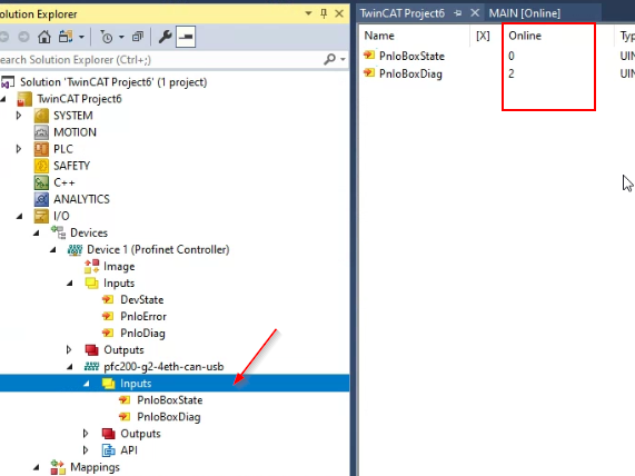
2=IOCC-AR is established, Connection is OK!
Variables Check
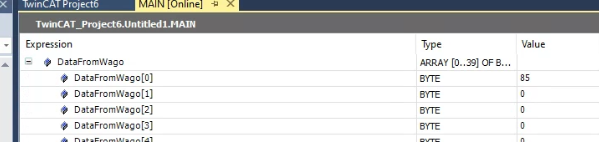
Finally we can write some values into the TwinCAT Side and check if the data is sent to the wago side or not.
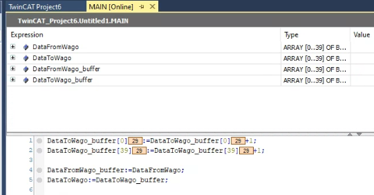
Firstly, we can receive the data that came from wago.
And then we can also check the data from twincat in the E!COCKPIT.
Good!Communication is OK!

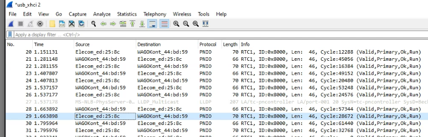
And also we can see the PNIO Packages are sent by using wireshark.
If the connection is not Established..
Please check these item:
- GSDML is correct or not
- The version of GSDML is 100% matched or not.
- The Correct Profinet I/O Controller is chosen as the I/O>Devices>Add New Item screen.
- The Task for PN Controller is ok or not.
- The cycle time is based on 2 or not.