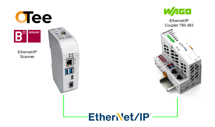
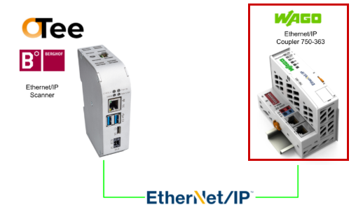
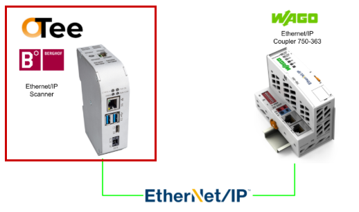
This is a new series where we’ll explore various topics using OTee, a Virtual PLC. In Episode 7, we’ll launch an Ethernet/IP Scanner on the OTee Platform and connect it to WAGO’s Ethernet/IP Coupler 750-363.
Additionally, we will now install OTea’s Virtual PLC on Berghof’s MC-Pi Pro and expand the article.
Alright, let’s enjoy the FA.
Foreword
Thank you from the bottom of my heart for visiting my technical blog and YouTube channel.
We are currently running the “Takahashi Chris” radio show with Full-san (full@桜 八重 (@fulhause) / X) which I deliver every Wednesday night.
Sharing, not hoarding, technical knowledge
We publish technical information related to factory production technology and control systems for free, through blogs and videos.
With the belief that “knowledge should be accessible to everyone,” we share practical know-how and real-world troubleshooting cases from our own field experience.
The reason we keep it all free is simple: to help reduce the number of people who struggle because they simply didn’t know.
If you’ve ever thought:
- “Will this PLC and device combination actually work?”
- “I’m having trouble with EtherCAT communication—can someone test it?”
- “I want to try this remote I/O, but we don’t have the testing environment in-house…”
Feel free to reach out!If lending equipment or sharing your configuration is possible, we’re happy to verify it and share the results through articles and videos.
(We can keep company/product names anonymous if requested.)
How can you support us?
Currently, our activities are nearly all unpaid, but creating articles and videos takes time and a proper testing environment.If you’d like to support us in continuing and expanding this content, your kind help would mean a lot.
Membership (Support our radio show)
This support plan is designed to enhance radio with Mr Full.
https://note.com/fulhause/membership/join
Amazon Gift List (equipment & books for content production)
Lists equipment and books required for content creation.
https://www.amazon.co.jp/hz/wishlist/ls/H7W3RRD7C5QG?ref_=wl_share
Patreon (Support articles & video creation)
Your small monthly support will help to improve the environment for writing and verifying articles.
https://www.patreon.com/user?u=84249391
Paypal
A little help goes a long way.
https://paypal.me/soup01threes?country.x=JP&locale.x=ja_JP
Just trying to share things that could’ve helped someone—if only they’d known.
Your support helps make knowledge sharing more open and sustainable.
Thank you for being with us.
soup01threes*gmail.com
Technical knowledge shouldn’t be kept to ourselves.
Referece Link
http://soup01.com/en/category/otee_en/
750-363?
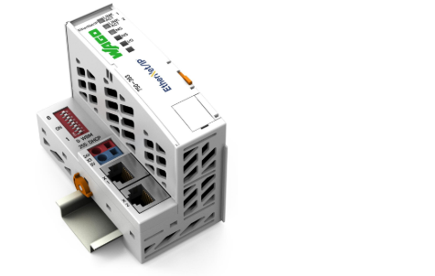
The 750-363 EtherNet/IP Fieldbus Coupler connects EtherNet/IP fieldbus systems to the modular WAGO I/O system. The fieldbus coupler also detects all connected I/O modules and creates a local process image.
The 750-363 features two Ethernet interfaces and an integrated switch, enabling fieldbus wiring in a line topology and eliminating the need for additional network devices such as switches or hubs.
Additionally, the DIP switches can be used to configure the final byte of the IP address and for IP address assignment (DHCP, BootP, static).
This coupler is designed for fieldbus communication within EtherNet/IP networks. It also supports various standard Ethernet protocols, including HTTP(S), BootP, DHCP, DNS, SNMP, and (S)FTP. The built-in web server displays the coupler’s status information while providing user configuration options.
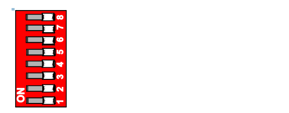
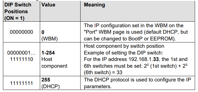
DIP switch
The 8-pole DIP switch is used to select the protocol for IP address configuration.
Additionally, to set the IP address as the address selection switch. An IP address consists of a network portion and a host portion.
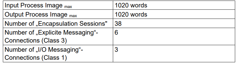
Specification
This is the specification for the WAGO 750-363 Ethernet/IP coupler.
Implementation
Wago Side
First, configure the WAGO Ethernet/IP coupler.
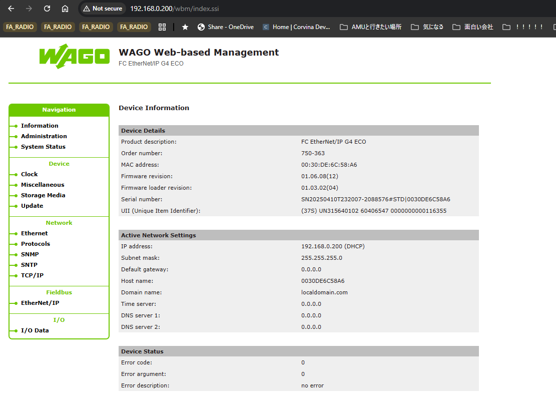
Web Server
First, set a fixed IP address via the DIP switches, then access the web server on the WAGO Ethernet/IP coupler 750-363.
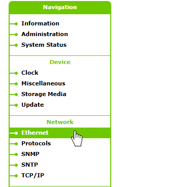
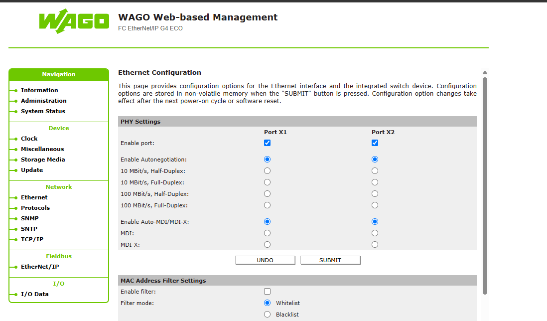
Network Ethernet
Click Network→Ethernet.
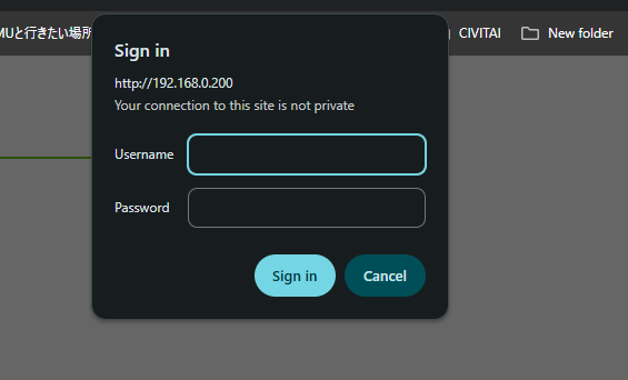
To change Ethernet settings, you must log in. These are the coupler’s default settings.
- Username:admin
- password
- Username:user
- password:user
Done!From this screen, you can configure settings such as enabling or disabling the PORT.
IP Configuration
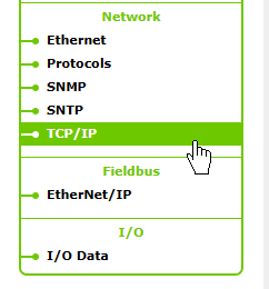
Next, to change the Ethernet/IP coupler’s IP address and other settings, click Network → TCP/IP.
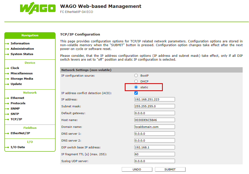
This is the TCP/IP settings screen.
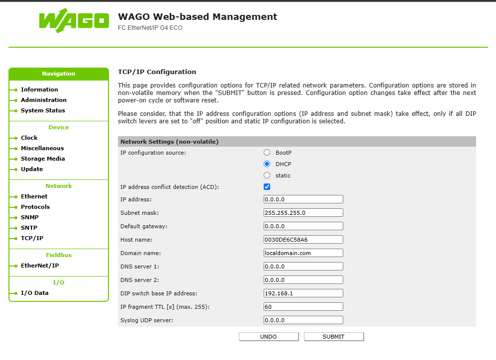
Set the IP address and click SUBMIT to enable the settings.
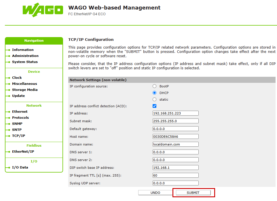
Also, don’t forget to set the IP configuration source to Static.
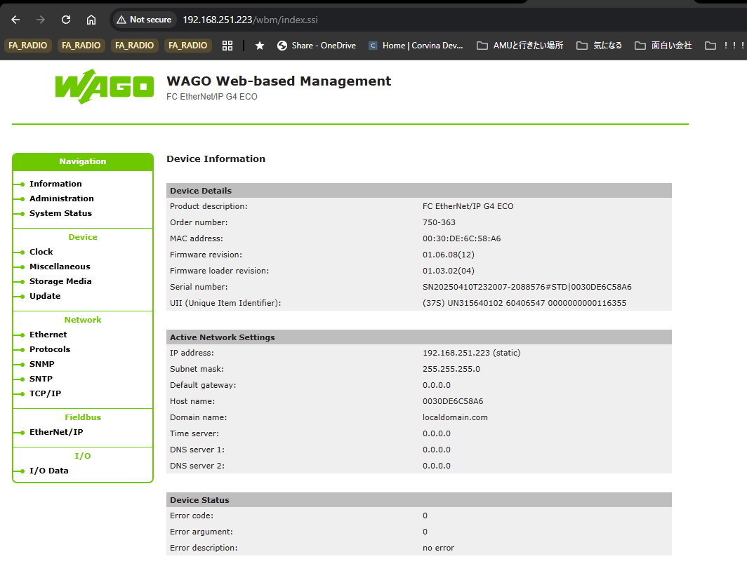
Done!The IP address has been changed.
Fieldbus
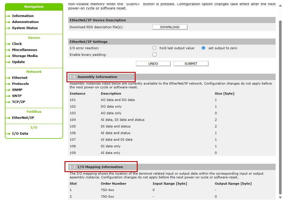
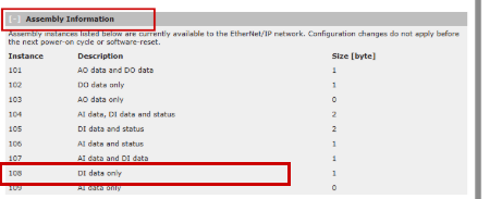
Next, verify the Ethernet/IP settings for the WAGO Ethernet/IP coupler. Click Fieldbus → Ethernet/IP.
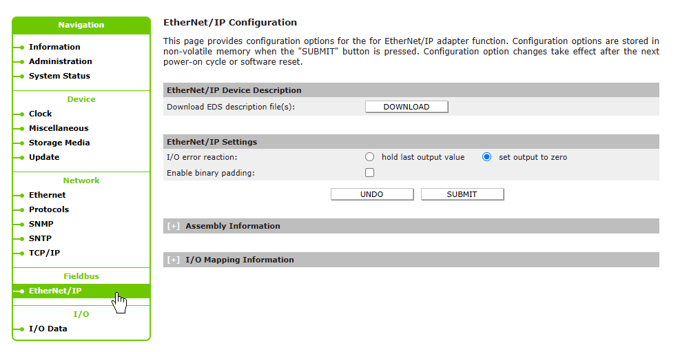
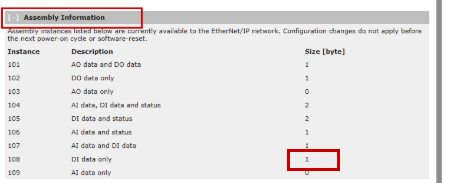
This time, only 750-1417 and 750-1515 are being used, so the size is set to 1 byte only in both the Assembly Information and I/O Mapping Information.
OTee Side
Next, configure the OTee side.
Add Ethernet/IP Settings
Access the OTee Platform and click the + button within your project.
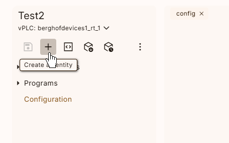
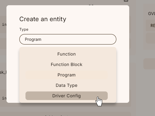
The new item addition screen will appear.
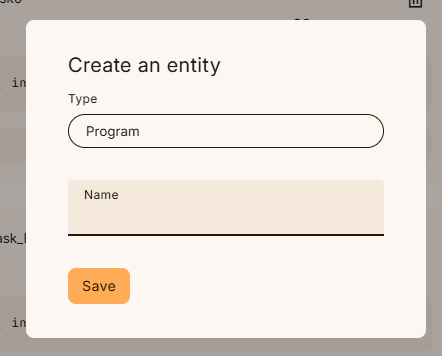
Configure the Driver Config from the drop-down list.
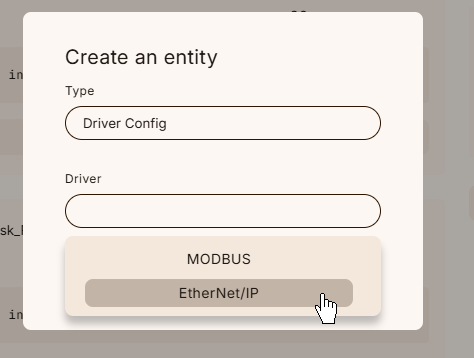
Next, configure EtherNet/IP from the Driver drop-down list.
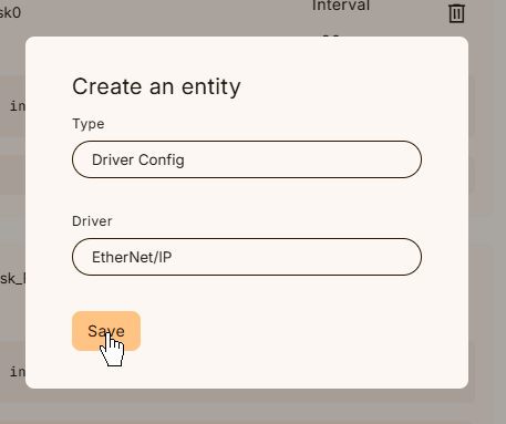
Click Save to apply the settings.
Add a client
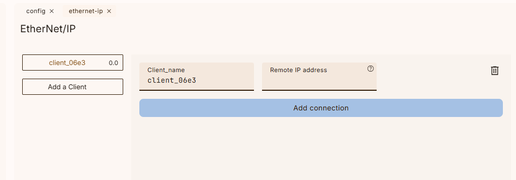
Next, open the Ethernet/IP settings screen and add a new Ethernet/IP Adapter by selecting “Add a Client”.
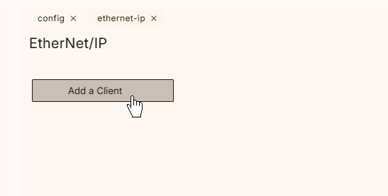
Done!The new Ethernet/IP Adapter has been added.
Remote IP address
Set the Remote IP Address field to match the IP address configured on the Beckhoff TwinCAT3 side.
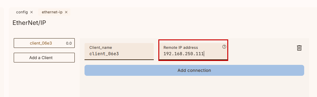
Configure it to match the WAGO Ethernet/IP coupler mentioned earlier.
Connect Configuration
We will now configure the Ethernet/IP settings between WAGO and OTEE Runtime.
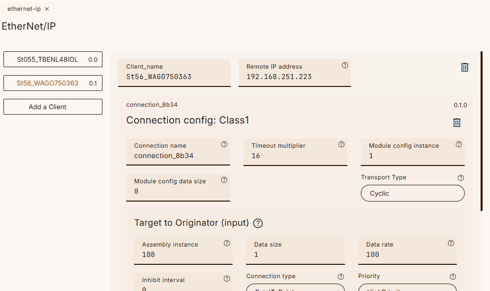
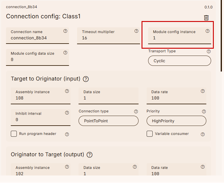
Connection Config
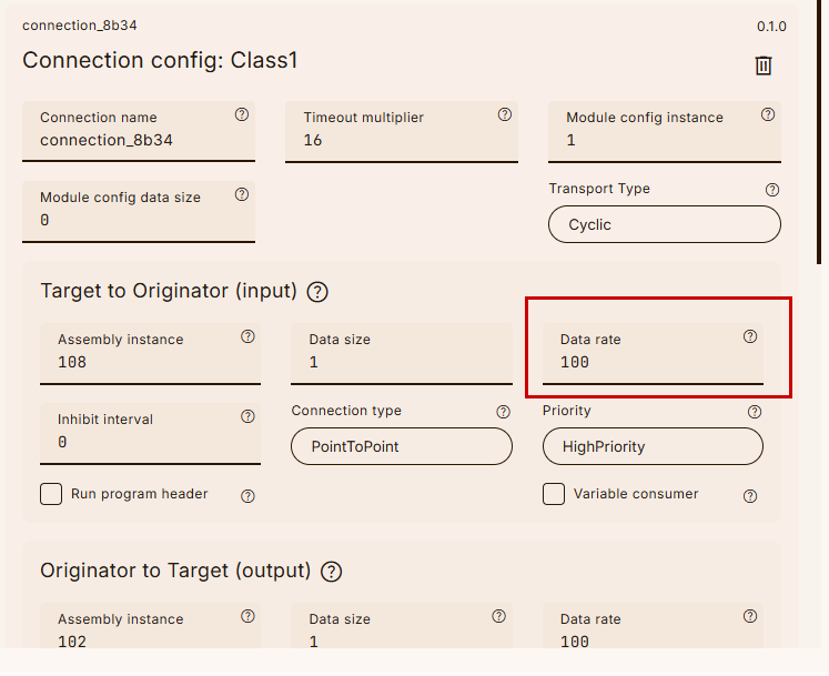
First, configure the communication settings for Class1 Config.
Module Config Instance
The Module Config Instance can be set to 1.
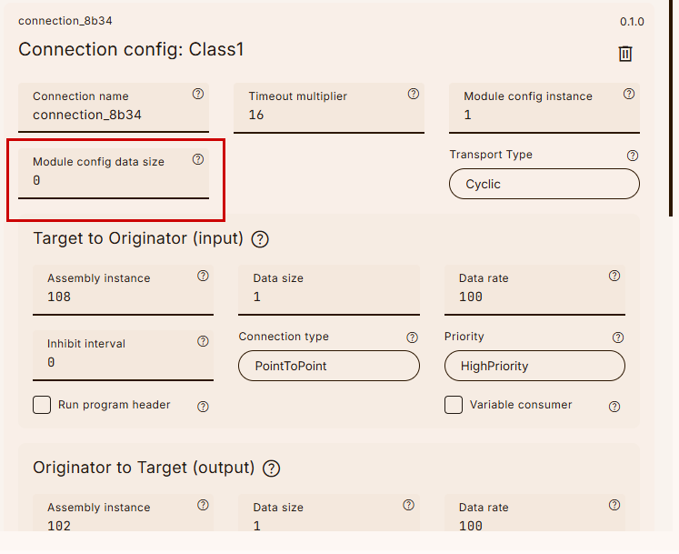
Module Config data size
Set the module configuration data size to 0.
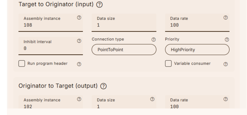
T→O
Next, configure the T→O input data section.
Assembly Instance
Set the Assembly Instance number for T→O to 108.
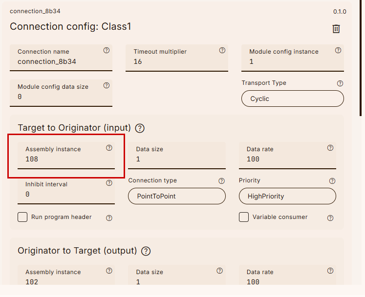
Earlier, the WAGO 750-363 Web Server indicated that Instance108 contains only DI data.
Data Size
Set the Data Size to 1.
Data rate
Set the communication cycle according to your application.
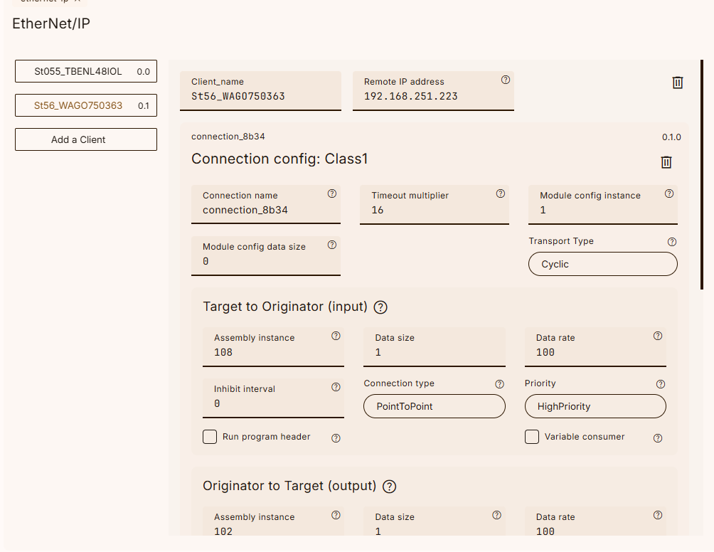
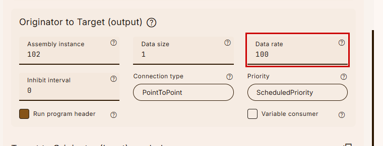
O→T
Going forward, let’s configure the O→T output data side.
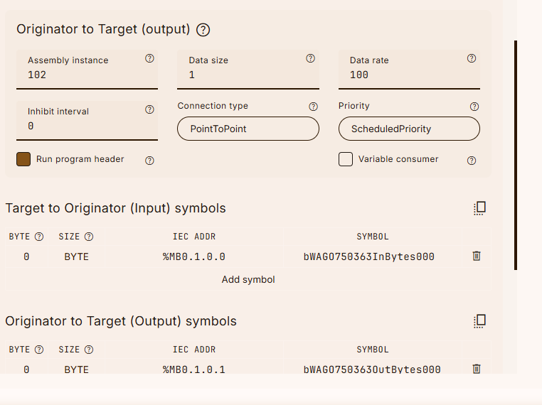
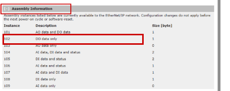
Assembly Instance
Set the Assembly Instance number to 102.
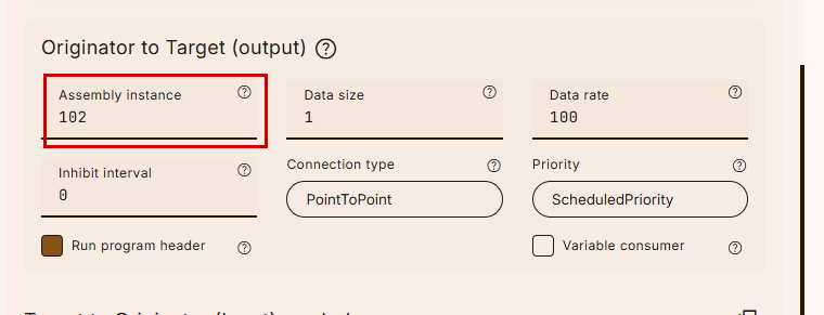
Earlier, the WAGO 750-363 Web Server indicated that Instance 102 only contains DO data.
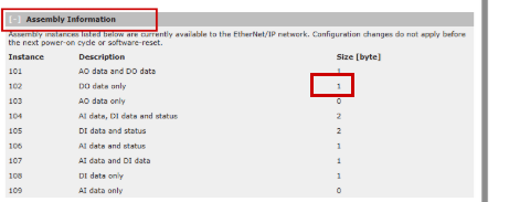
Data Size
Set the Data Size to 1.
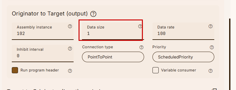
Earlier, the WAGO 750-363 Web Server indicated that Instance102 has a DO data size of 1.
Data rate
Set the communication cycle according to your application.
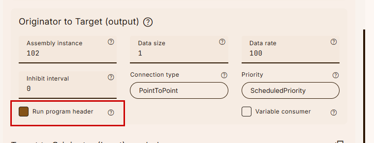
Run program header
Please check the box in the Run program header for output data.
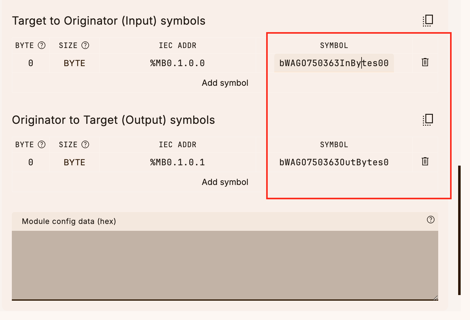
Rename the Tags
Finally, let’s set the Ethernet/IP symbol name.
Configuration
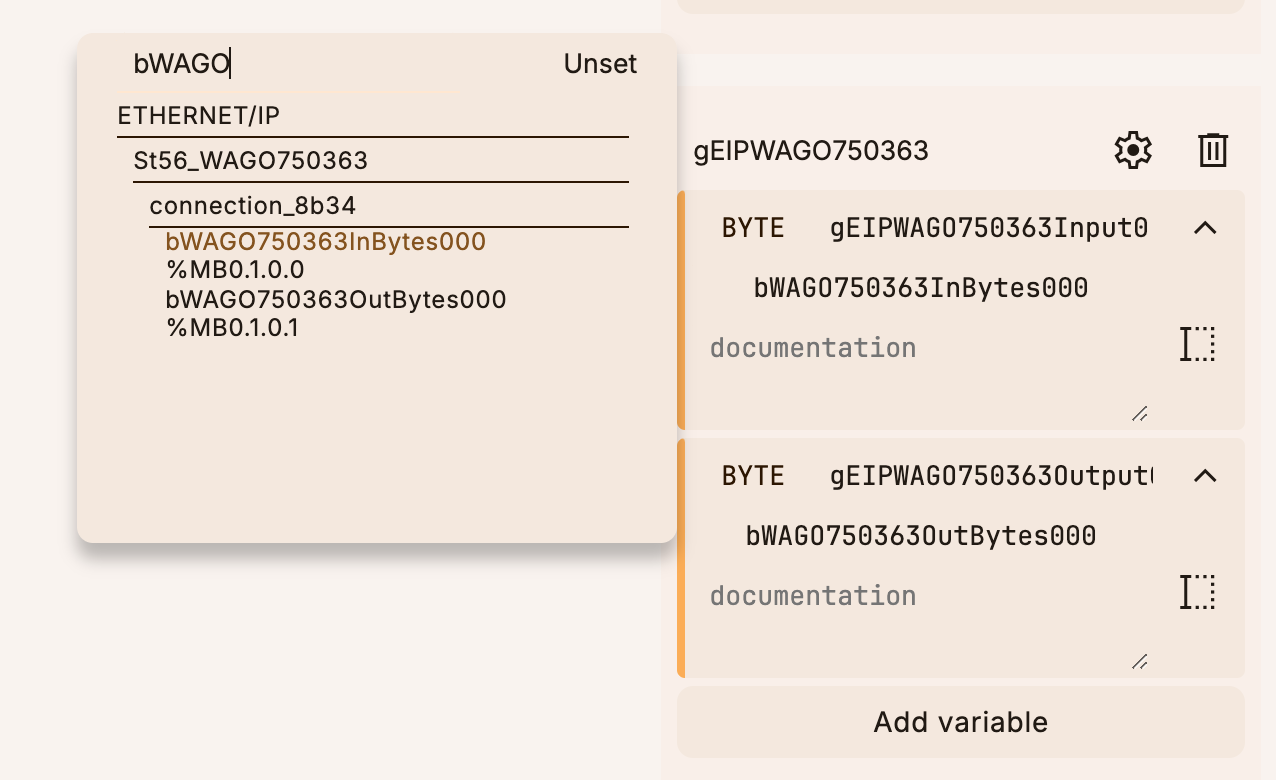
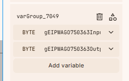
Next, click Configuration to declare a global variable.
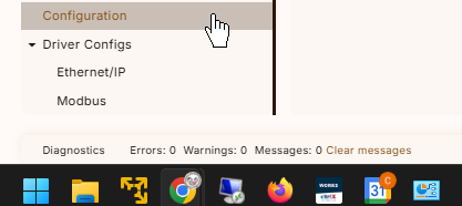
In this article, we define two global variables as shown in the figure below.
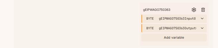
Let’s link it to the SYMBOL defined earlier in Ethernet/IP.
Program
This time, we’ll create a program.
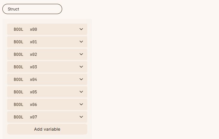
Data Type-dut_wago_750_4xx_8Points
This is a structure representing 8-point data.
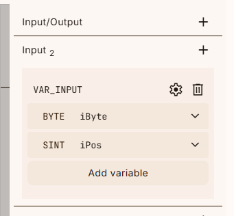
Function-fcGetBitFromByte
This function retrieves the current value (TRUE or FALSE) of a specific bit position from a Byte variable.
case iPos of
0:
fcGetBitFromByte := (iByte AND 1) <> 0;
1:
fcGetBitFromByte := (iByte AND 2) <> 0;
2:
fcGetBitFromByte := (iByte AND 4) <> 0;
3:
fcGetBitFromByte := (iByte AND 8) <> 0;
4:
fcGetBitFromByte := (iByte AND 16) <> 0;
5:
fcGetBitFromByte := (iByte AND 32) <> 0;
6:
fcGetBitFromByte := (iByte AND 64) <> 0;
7:
fcGetBitFromByte := (iByte AND 128) <> 0;
end_case;
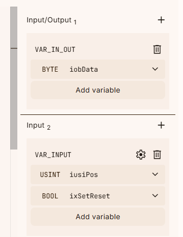
Function-fcSetBitToByte
This function changes the current value (TRUE or FALSE) of a specific bit position in a Byte variable.
case iusiPos of
0:
if ixSetReset then
iobData := iobData OR 1;
else
iobData := iobData AND 254;
end_if;
1:
if ixSetReset then
iobData := iobData OR 2;
else
iobData := iobData AND 253;
end_if;
2:
if ixSetReset then
iobData := iobData OR 4;
else
iobData := iobData AND 251;
end_if;
3:
if ixSetReset then
iobData := iobData OR 8;
else
iobData := iobData AND 247;
end_if;
4:
if ixSetReset then
iobData := iobData OR 16;
else
iobData := iobData AND 239;
end_if;
5:
if ixSetReset then
iobData := iobData OR 32;
else
iobData := iobData AND 223;
end_if;
6:
if ixSetReset then
iobData := iobData OR 64;
else
iobData := iobData AND 191;
end_if;
7:
if ixSetReset then
iobData := iobData OR 128;
else
iobData := iobData AND 127;
end_if;
end_case;
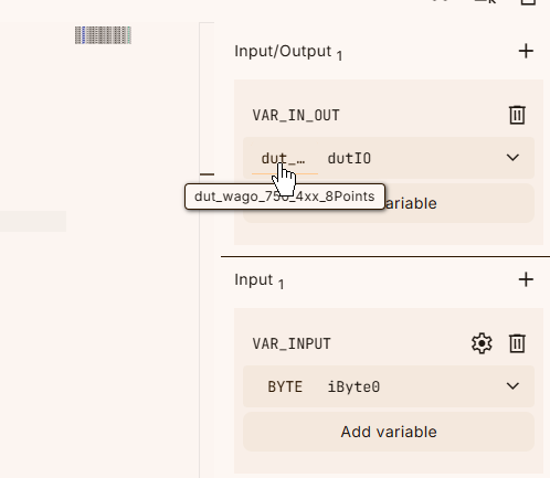
Function Block-fb_Wago_7501417
This is the function block for the WAGO 750-1417 8-point input module.
dutIO.x00:=fcGetBitFromByte(iByte:=iByte0,iPos:=0);
dutIO.x01:=fcGetBitFromByte(iByte:=iByte0,iPos:=1);
dutIO.x02:=fcGetBitFromByte(iByte:=iByte0,iPos:=2);
dutIO.x03:=fcGetBitFromByte(iByte:=iByte0,iPos:=3);
dutIO.x04:=fcGetBitFromByte(iByte:=iByte0,iPos:=4);
dutIO.x05:=fcGetBitFromByte(iByte:=iByte0,iPos:=5);
dutIO.x06:=fcGetBitFromByte(iByte:=iByte0,iPos:=6);
dutIO.x07:=fcGetBitFromByte(iByte:=iByte0,iPos:=7);
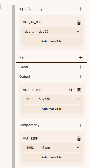
Function Block-fb_Wago_7501515
This is the function block for the WAGO 750-1515 8-point output module.
_xTemp:=fcSetBitToByte(iusiPos:=0,ixSetReset:=dutIO.x00,iobData:=oByte0);
_xTemp:=fcSetBitToByte(iusiPos:=1,ixSetReset:=dutIO.x01,iobData:=oByte0);
_xTemp:=fcSetBitToByte(iusiPos:=2,ixSetReset:=dutIO.x02,iobData:=oByte0);
_xTemp:=fcSetBitToByte(iusiPos:=3,ixSetReset:=dutIO.x03,iobData:=oByte0);
_xTemp:=fcSetBitToByte(iusiPos:=4,ixSetReset:=dutIO.x04,iobData:=oByte0);
_xTemp:=fcSetBitToByte(iusiPos:=5,ixSetReset:=dutIO.x05,iobData:=oByte0);
_xTemp:=fcSetBitToByte(iusiPos:=6,ixSetReset:=dutIO.x06,iobData:=oByte0);
_xTemp:=fcSetBitToByte(iusiPos:=7,ixSetReset:=dutIO.x07,iobData:=oByte0);
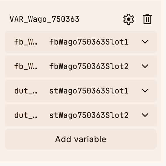
MAIN
Finally, in the MAIN program, we use the global variables declared earlier as external variables.
Here are the struct and FB variables created in this article.
The program in this article simply outputs the same number to DO when the DI input becomes TRUE.
fbWago750363Slot1(
(* Inputs *)
iByte0 := gEIPWAGO750363Input0,
(* InOuts *)
dutIO := stWago750363Slot1
(* Outputs *)
);
fbWago750363Slot2(
(* Inputs *)
(* InOuts *)
dutIO := stWago750363Slot2,
(* Outputs *)
oByte0 => gEIPWAGO750363Output0
);
stWago750363Slot2.x00:=stWago750363Slot1.x00;
stWago750363Slot2.x01:=stWago750363Slot1.x01;
stWago750363Slot2.x02:=stWago750363Slot1.x02;
stWago750363Slot2.x03:=stWago750363Slot1.x03;
stWago750363Slot2.x04:=stWago750363Slot1.x04;
stWago750363Slot2.x05:=stWago750363Slot1.x05;
stWago750363Slot2.x06:=stWago750363Slot1.x06;
stWago750363Slot2.x07:=stWago750363Slot1.x07;
Download
Finally, download the project to OTe Runtime.
Result
You can verify the operation from this video.