This is a new series of articles in which we will conduct various tests using UNITRONICS’ UniStream® series and UniLogic. In Part 2, we will implement various coil functions commonly used in ladder circuits using UniLogic.
In Part 2, we will use the following devices:
- UNITRONICS US5-C10-TA30

Reference Link
Implementation1-rising-edge detection contact · Toggle coil
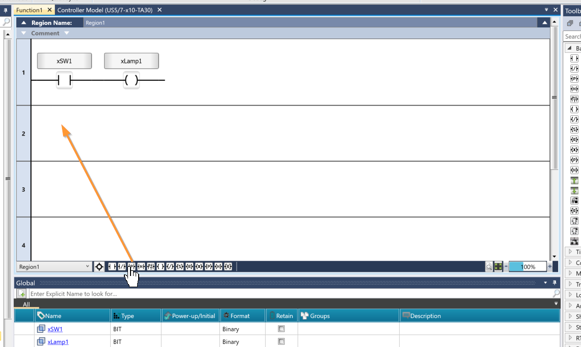
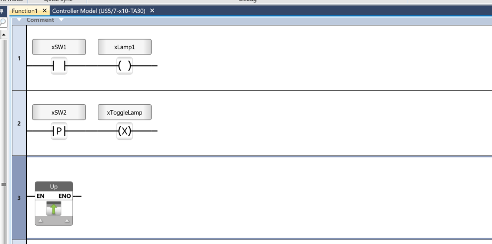
The rising-edge detection contact outputs a one-shot pulse for a single scan when the linked bit operand changes from OFF (logical 0) to ON (logical 1). To add a rising-edge detection contact, you can do so directly from the circuit using the icon located at the bottom of the Ladder Editor.
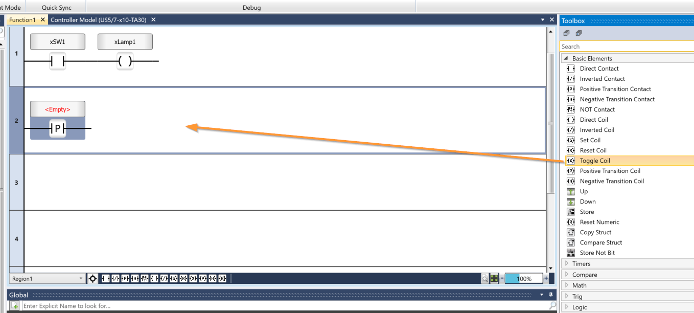
Next, we’ll use a toggle coil. A common example of a toggle coil is a light switch. When you turn on the light, it stays on until you flip the switch, at which point it turns off. The light then remains off until you flip the switch again to turn it back on. Add a toggle coil from the Toolbox.
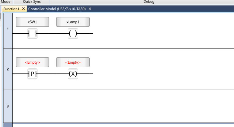
Done!Next, please declare it as a global variable.
Results
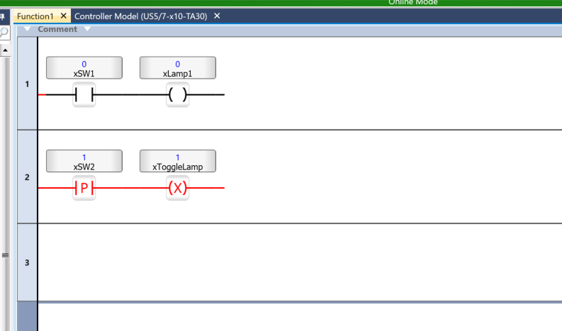
Next, I’ll check the operation of the toggle coil. The startup detection turns ON for only one cycle, but xToggleLamp still remains ON.
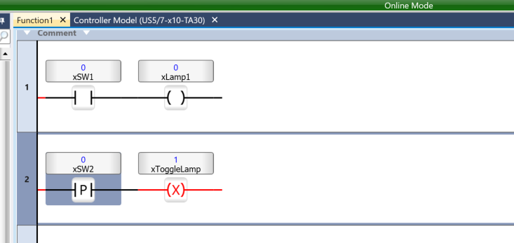
Of course, even if you turn SW2 off, xToggleLamp remains on.
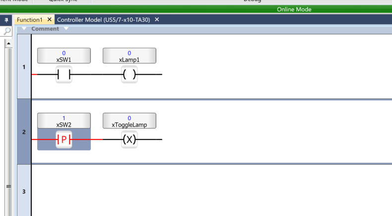
Then, when I turned xSW2 on again, xToggleLamp switched from ON to OFF.
Implementation2-Up/Down Elements
UP/DOWN refers to components that inherit the RLO of a ladder rung without being linked to a tag.
- The Up element sets the output signal Out to TRUE for one cycle only when the input signal In changes to TRUE. Otherwise, the value of Out is FALSE.
- The Down element sets the output signal Out to TRUE for one task cycle only when the input signal In changes to FALSE. Otherwise, the value of Out is FALSE.
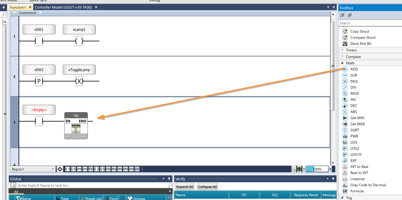
Add the component from the Toolbox to the circuit.
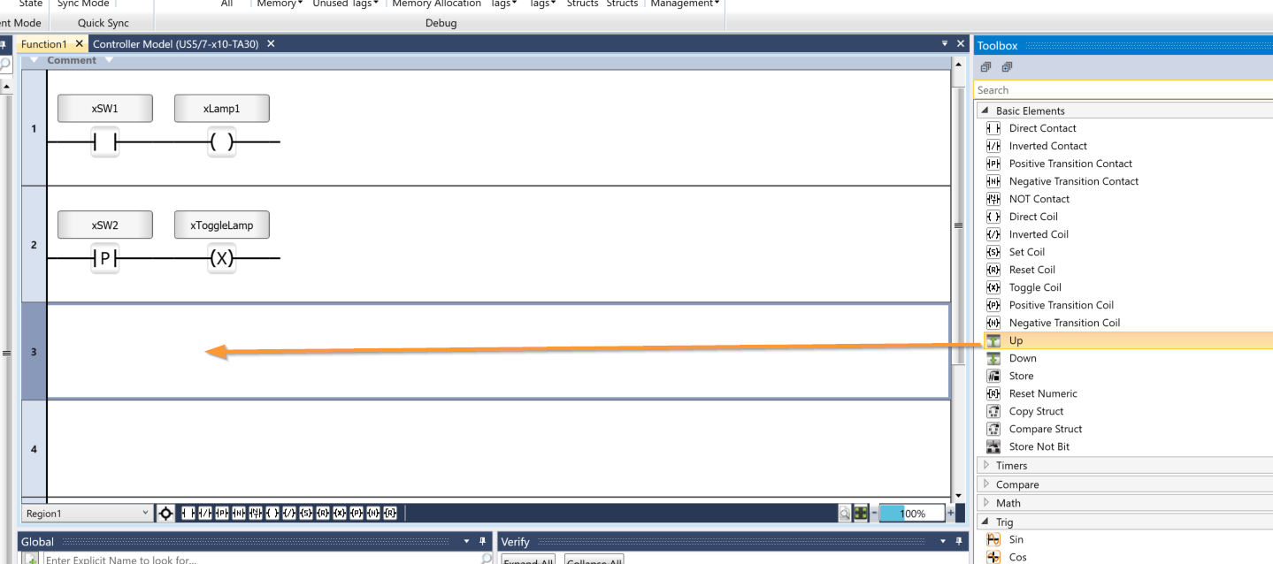
Done!The UP component has been added to the circuit.
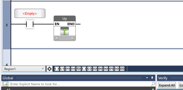
Next, add an A contact before the UP component.
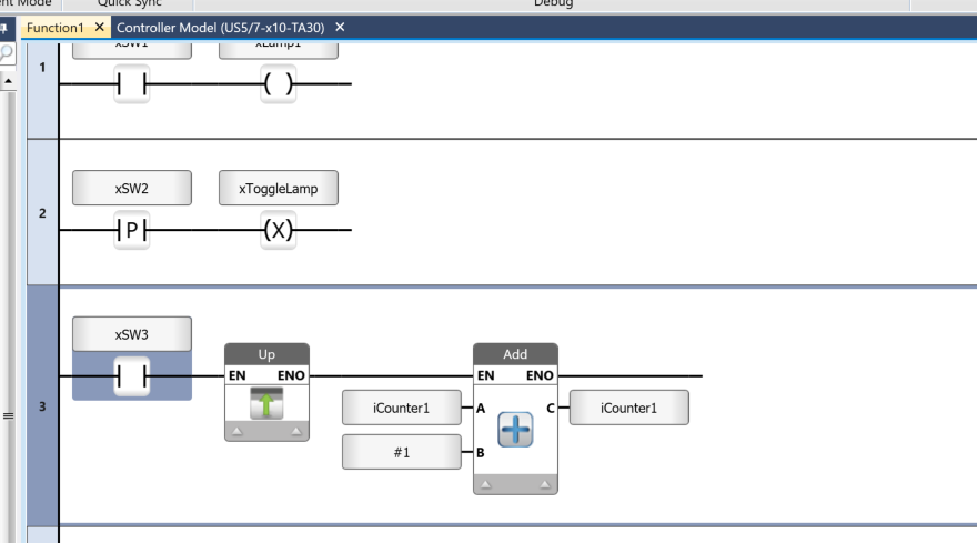
Next, let’s add an ADD component to the Up execution RLO.
Next, declare the variables as usual.
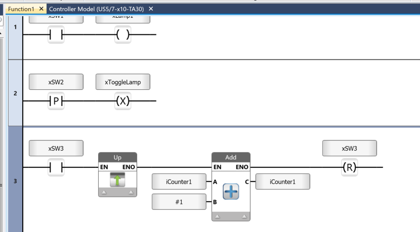
Next, after running the ADD function, add a Reset Coil.
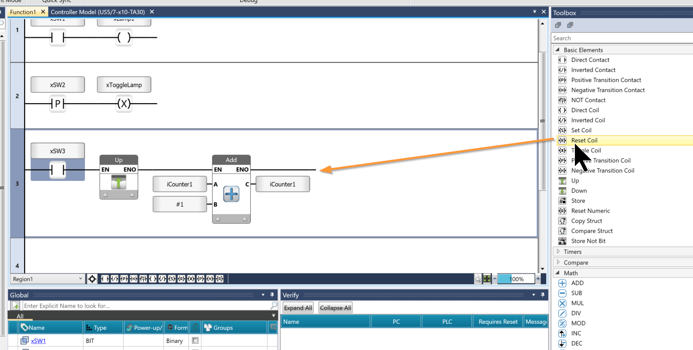
I configured the xSW3 to reset when the Reset Coil switch is set to ON.
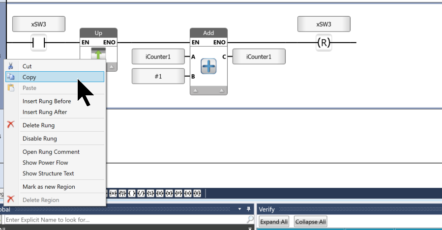
Next, we’ll duplicate the Rung3 circuit.
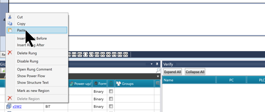
Paste the circuit onto Rung4.
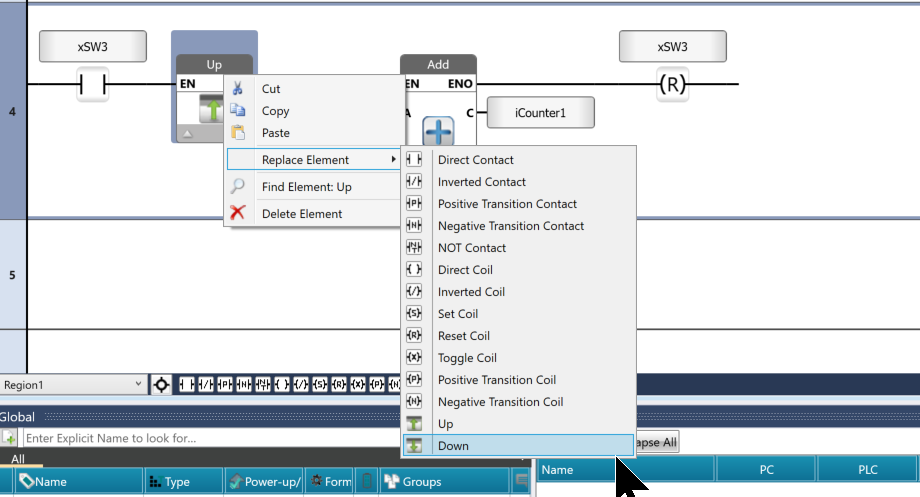
UniLogic includes a feature called “Replace Element,” which allows you to replace components in a circuit with other components. In this example, we will replace the “Up” component with a “Down” component.
Next, let’s declare a variable using the usual procedure.
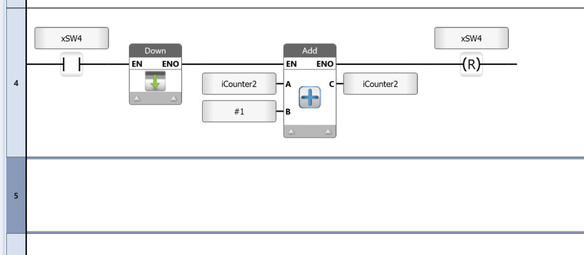
Results
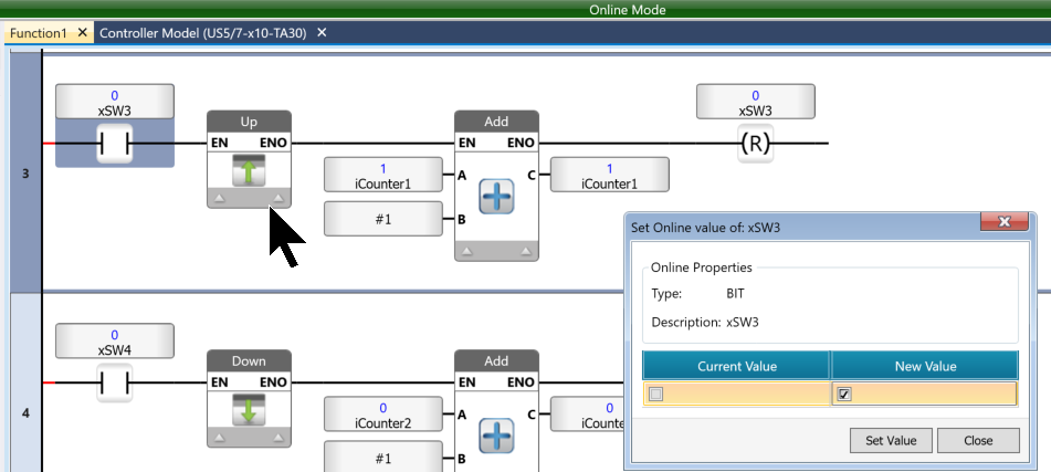
I found that when xSW3 is turned on, iCounter increments by only 1.
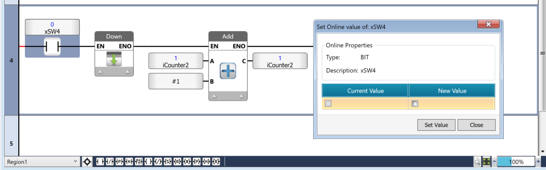
Next, even when I switch xSW4 from OFF to ON, iCounter2 doesn’t increment.
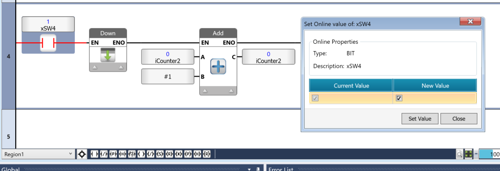
Next, when xSW4 switches from ON to OFF, iCounter2 will finally increment by 1.
Implementation3-Timer
Use this timer to delay the activation of the output. When the timer completes its operation, the TD timer output bit turns ON.
- The preset value is initially loaded into the current value when the timer is first detected.
- When the TON timer’s input condition goes high (RLO=TRUE), the timer begins decrementing.
- When the timer’s current value reaches 0 and the timer’s input condition is still ON, the timer output bit turns ON. The timer output bit remains ON until the input condition goes low (RLO=FALSE).
- When the TON timer’s input condition goes low (RLO=FALLSE), the preset value is loaded into the current value. If the input condition goes low while the timer is running:
- The timer stops and reloads the preset value.
- The current value is not retained.
- The timer output bit remains OFF.
- When the input condition is met (RLO positive), the timer resumes decrementing from the preset value.
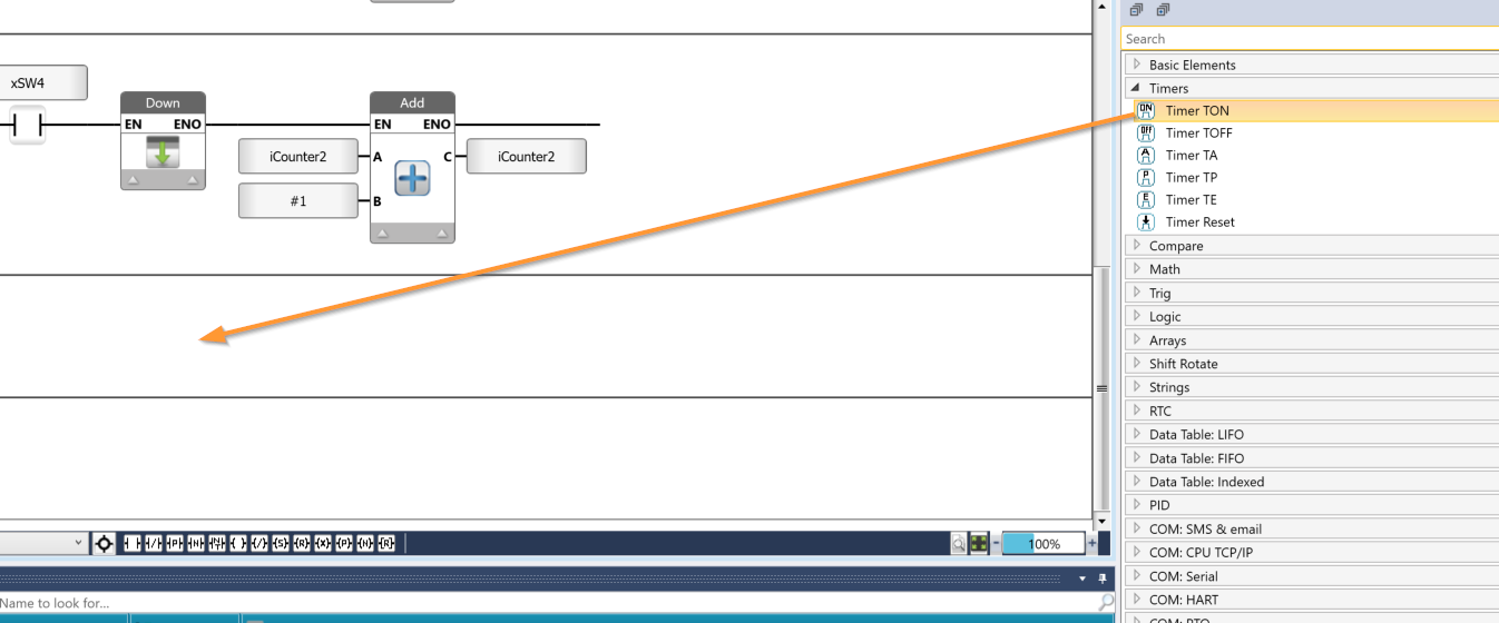
From the Toolbox, select Timers → Timer TON and add it to the circuit.
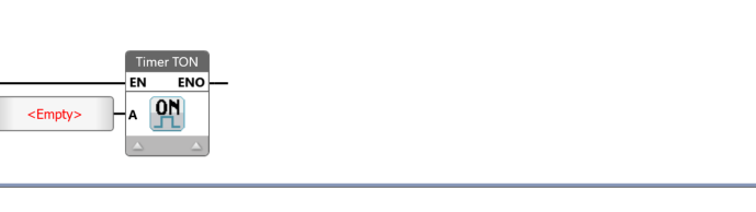
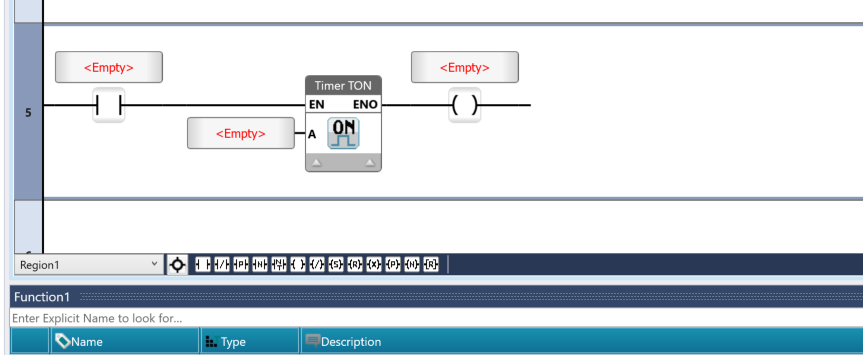
Done!
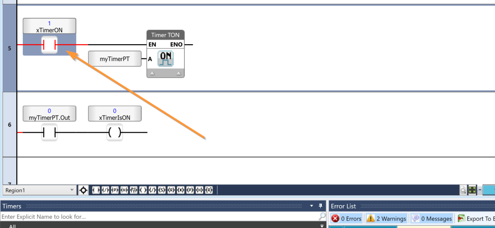
Next, add contact A and the coil as shown in the figure below.
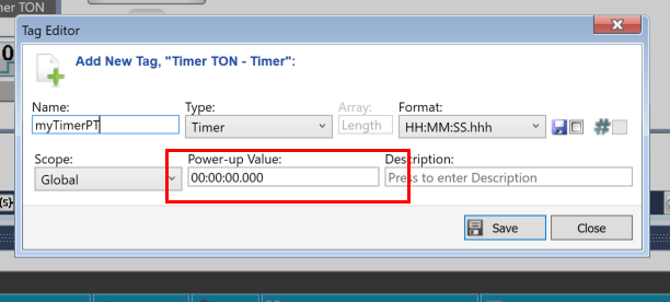
Next, declare the TIMER variable in the “A” parameter of TIMER TON.
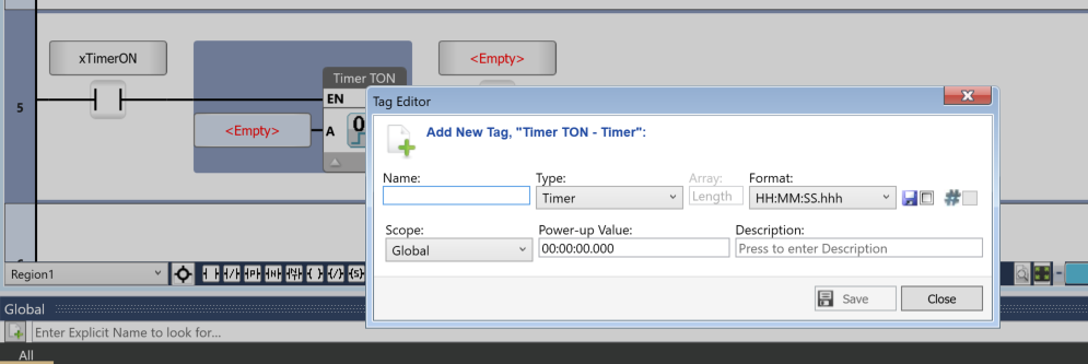
“Power-up Value” refers to the initial value.
Set the initial value to 5 seconds, as shown in the figure below.
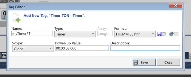
Done!
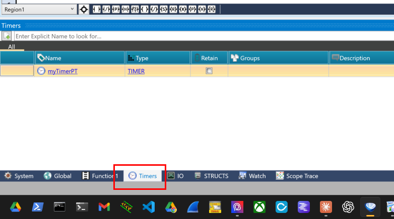
You can view the timer variables currently declared in the project from the Timers tab.
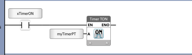
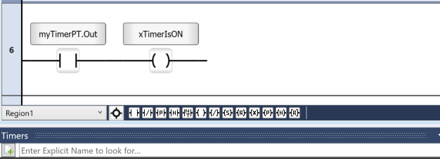
Finally, let’s check whether the timer is currently ON or OFF using Timer.Out, as shown in the figure below.
Results
First, set xTimerON to True.
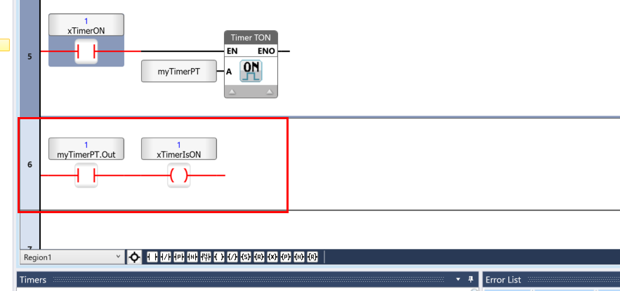
Then, after 5 seconds, `myTimerPT.Out` will be set to `True`.
Implementation4-Current timer value
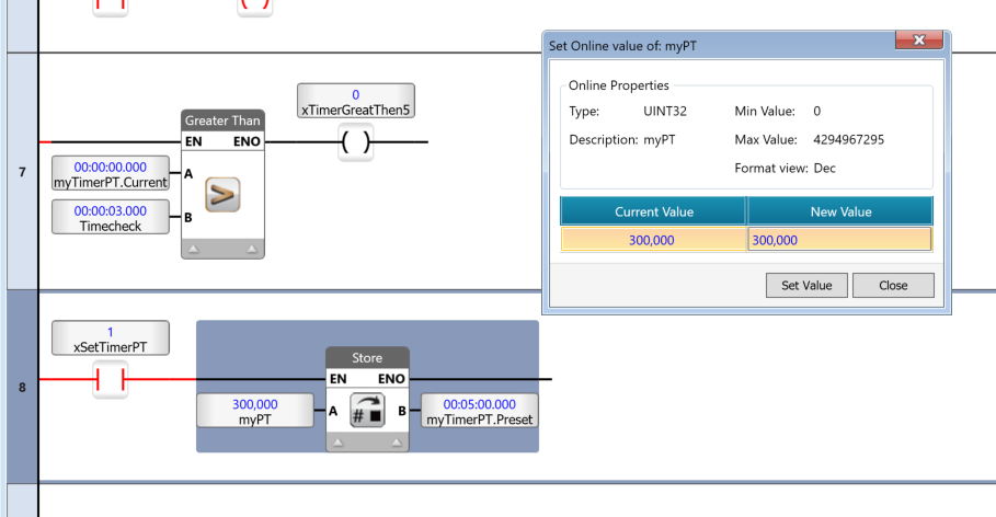
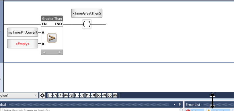
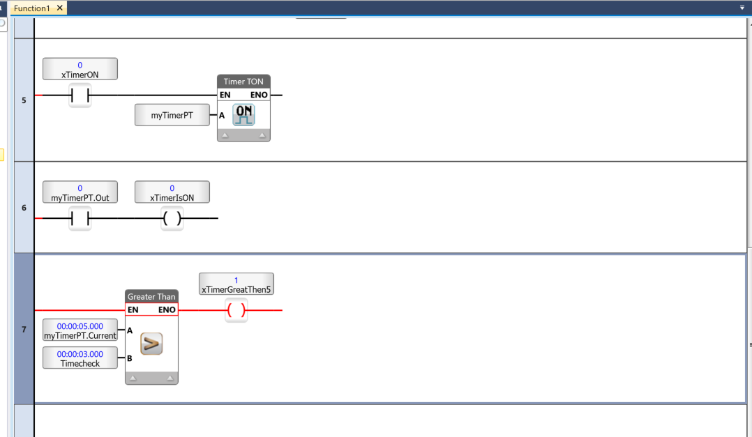
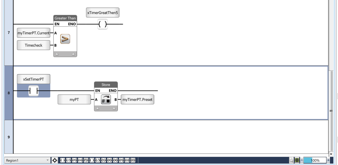
Next, we’ll check the current time value of the timer we defined earlier by accessing `MyTimerPT.Current` and using a “Greater Than” block to compare it.
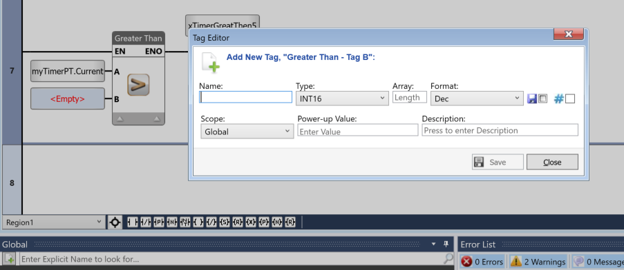
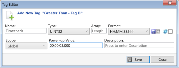
Next, define the variables to be compared with MyTimerPT.Current.
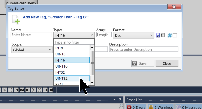
Please set the Type to UINT32.
Set the format to HH:MM:SS:hhh.
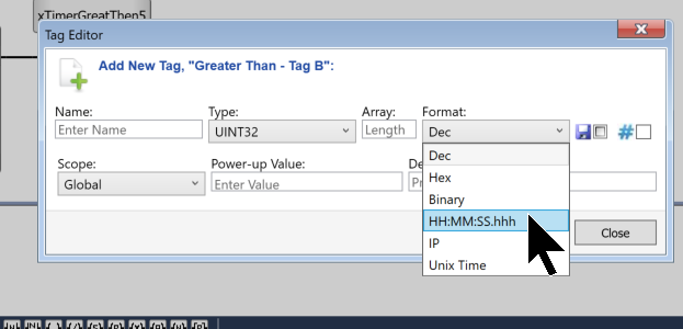
Next, just set the variable name and the Power-up Value, and you’re all set.
Results
The initial value stored in the timer is 5 seconds.
And once you start the timer, the time will keep ticking down.
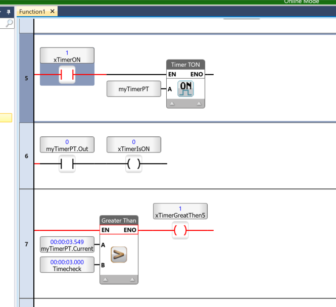
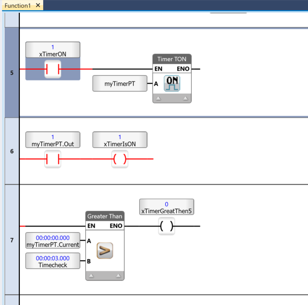
When the current elapsed time reaches 0 seconds, xTimerIsON becomes TRUE.
Implementation5-Changing the timer settings
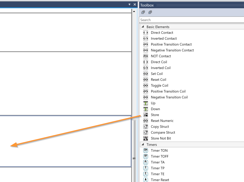
Finally, we will change the time measurement settings for the TIMER. In this example, we will use the STORE function, which allows us to store an integer tag or a constant value (Tag A) into an integer data tag (Tag B).
Add the STORE function to the circuit from the Toolbox.
Create a program like the one shown below so that you can set the time for myTimerPT.
Results
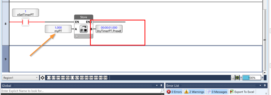
If you first store 1000 in `myPT`, the value of `myTimer.PT` will be set to 1 second.
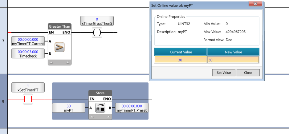
Next, if you change myPT to 30, the setting for myTimer.PT will be 30 seconds.
Finally, if you set myPT to 300, the value for myTimer.PT will be 5 minutes.