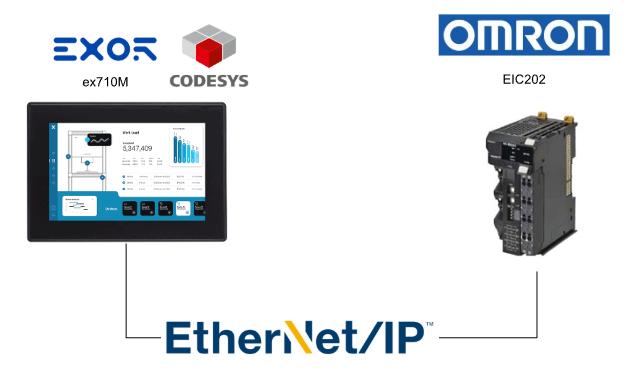
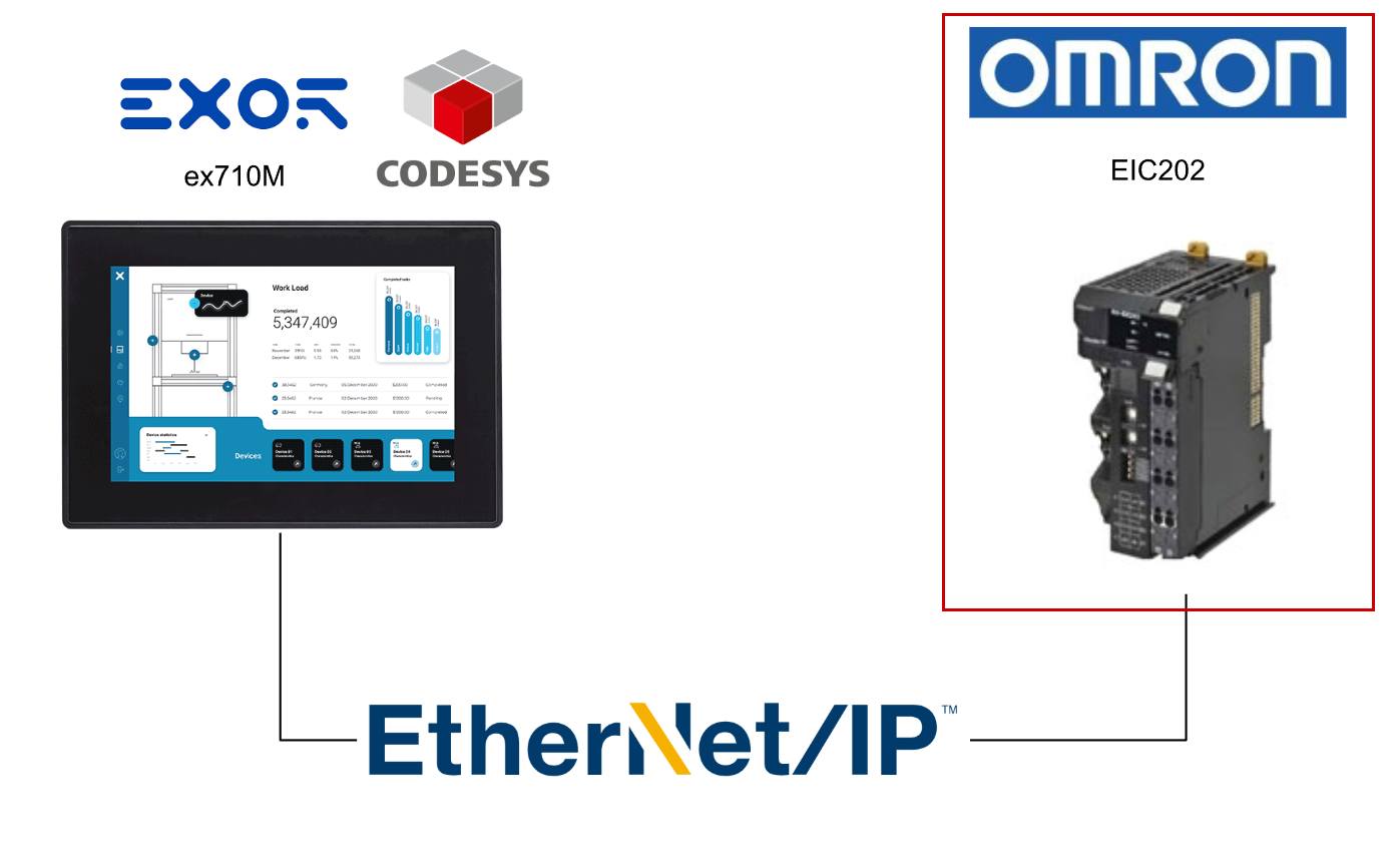
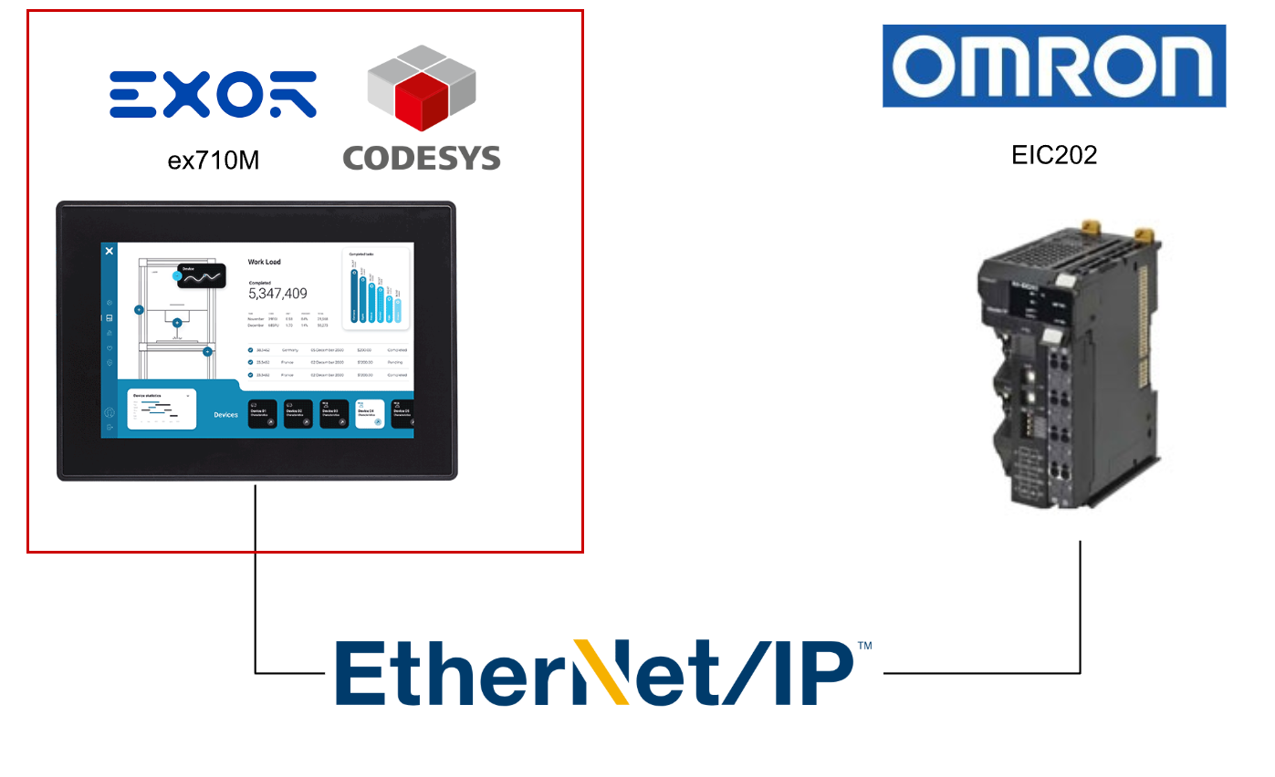
In this article, we’ll connect Omron’s Ethernet/IP coupler EIC202 and Codesys Runtime via Ethernet/IP.
Let’s enjoy FA!
Implementation
Now, let’s actually create the project.
Omron Side
First, we will configure Omron’s Ethernet/IP Coupler EIC202.
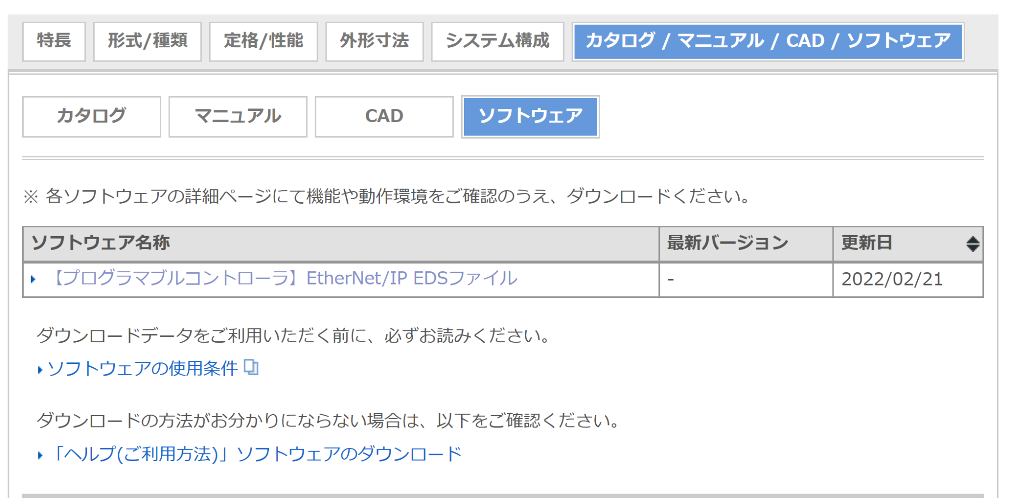
Download EDS
Similarly, please download the EDS FILE for Omron’s EIC202 from the link below.
https://www.fa.omron.co.jp/products/family/3955/download/software.html
Network Configurator Tools
Next, launch Network Configurator Tools to set the IP address of the EIC202.
Connection
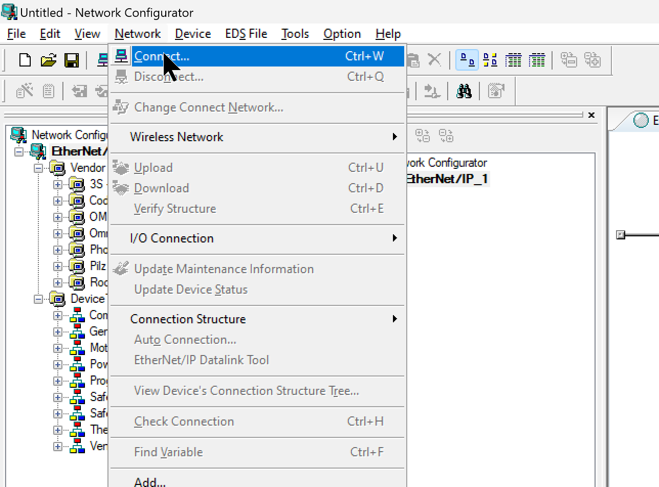
Click Network→Connect.
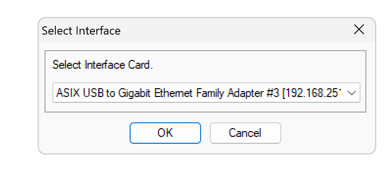
Set the Ethernet interface that connects your PC and the Omron EIC202, then click OK to proceed.
The network search screen will be displayed.
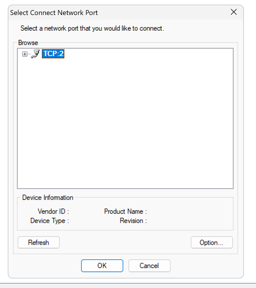
The EIC202 currently on the network will be found. Select that device and click OK to proceed.

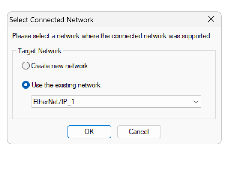
Click OK to proceed.
EIC202 IP Address Setting
Next, to set the IP address of the EIC202, click Tools→Setup TCP/IP Configuration.
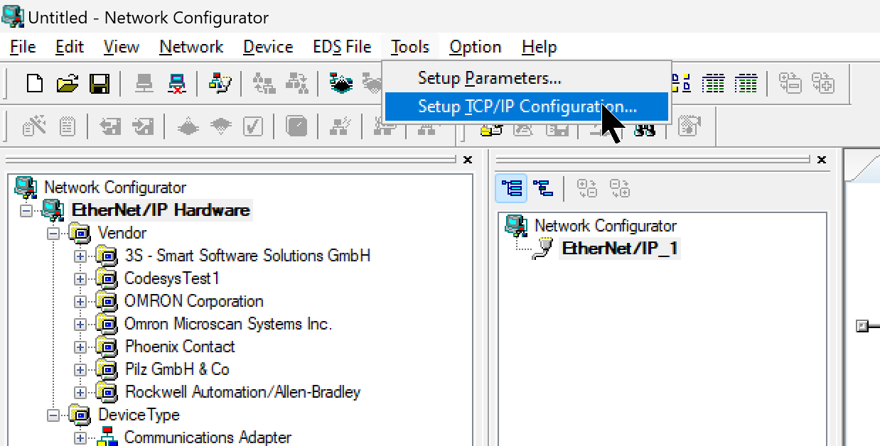
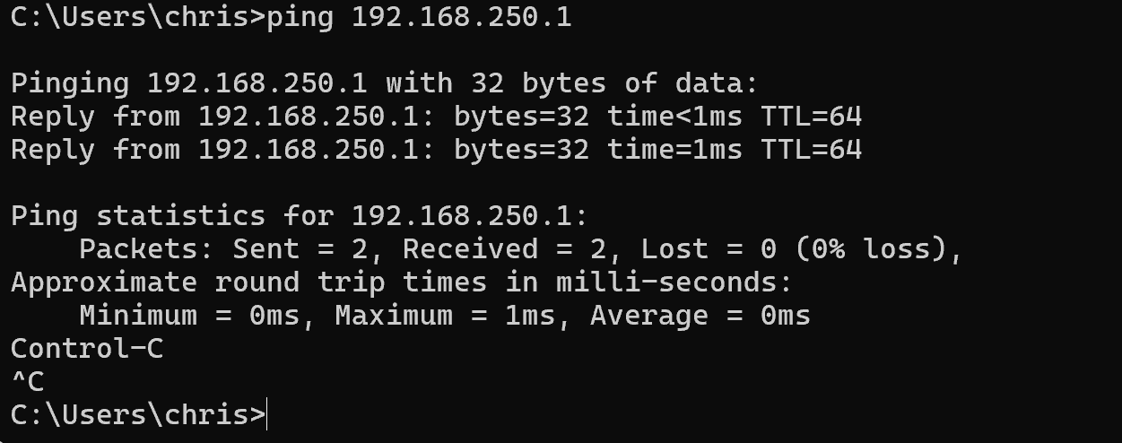
When all DIP switches on the EIC202 are set to 0, the default IP address is 192.168.250.1.
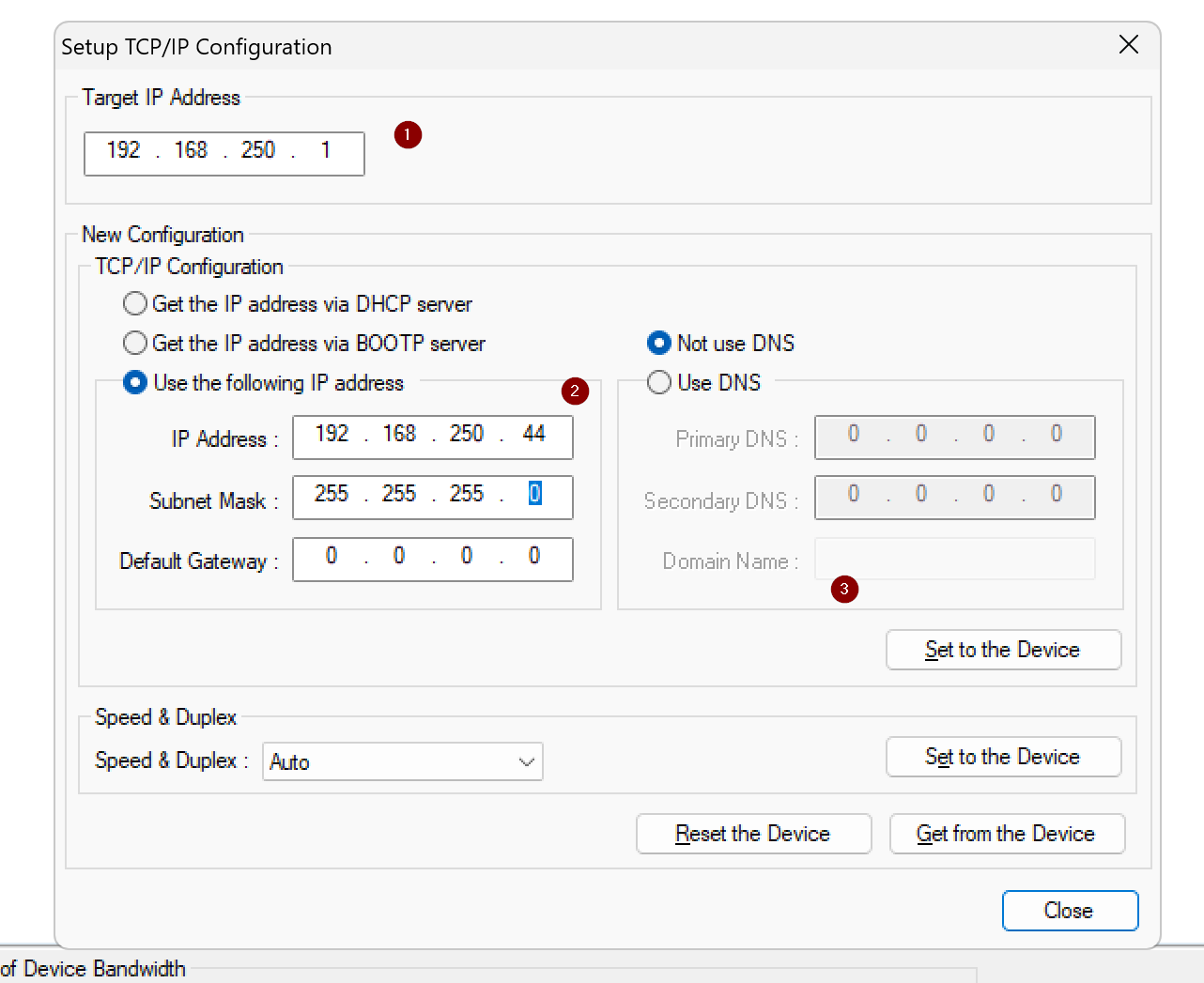
This IP configuration screen will appear.
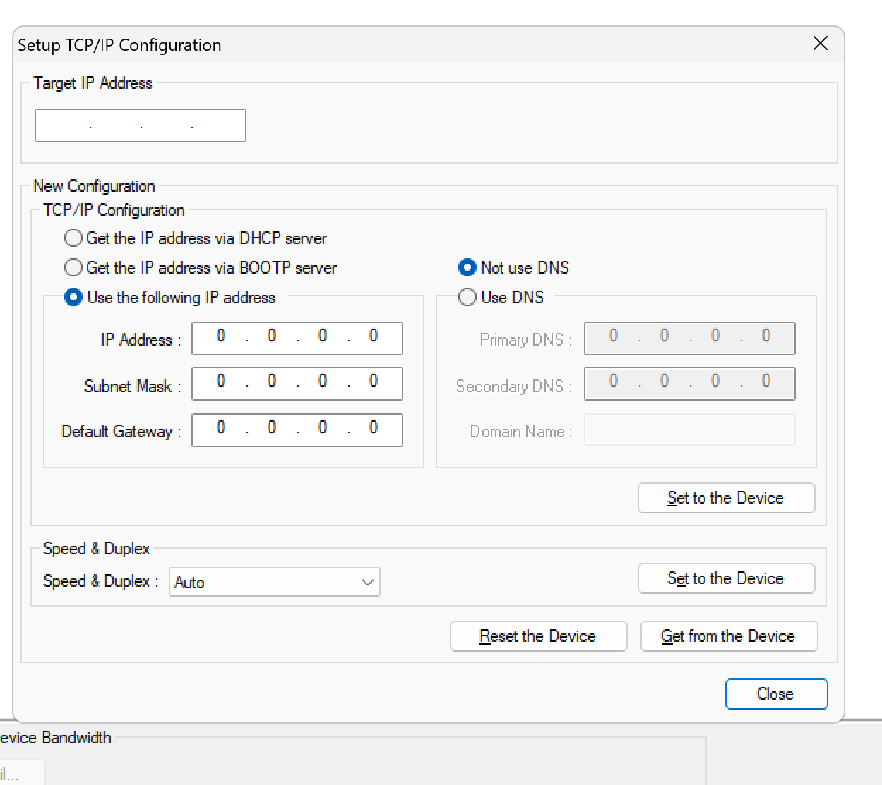
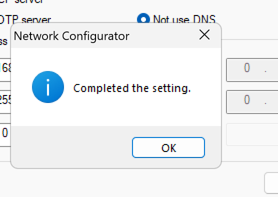
Set Target IP to the current IP address of the connected Omron EIC202, enter the new network settings in New Configuration, and finally write the settings to the EIC202 with Set to the Device.
Done!
NX IO Configurator
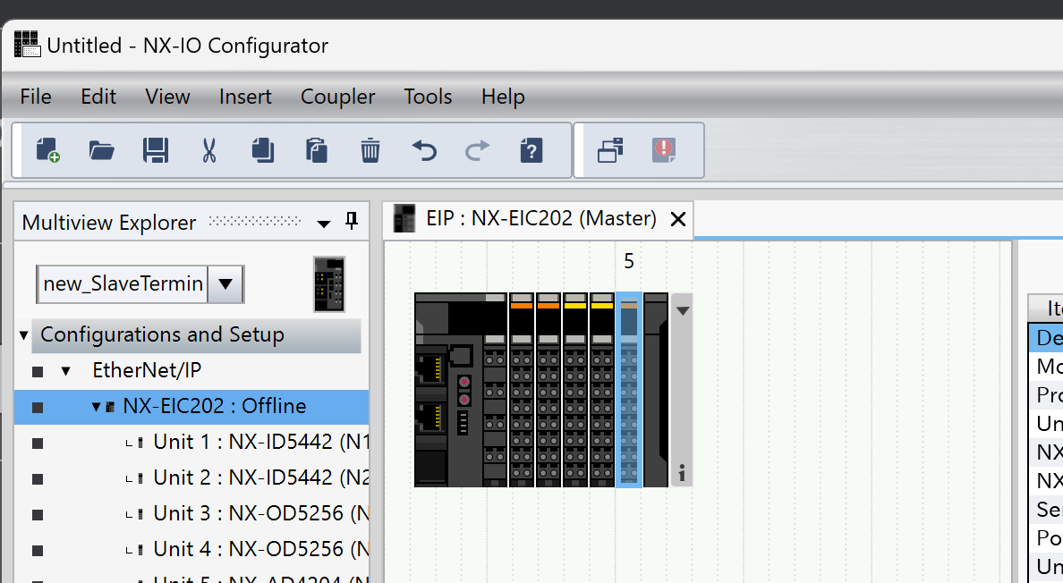
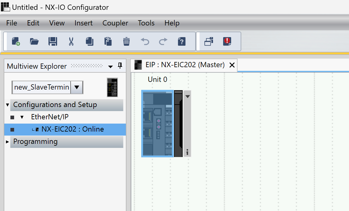
Next, launch NX IO Configurator to configure the modules installed on the EIC202.
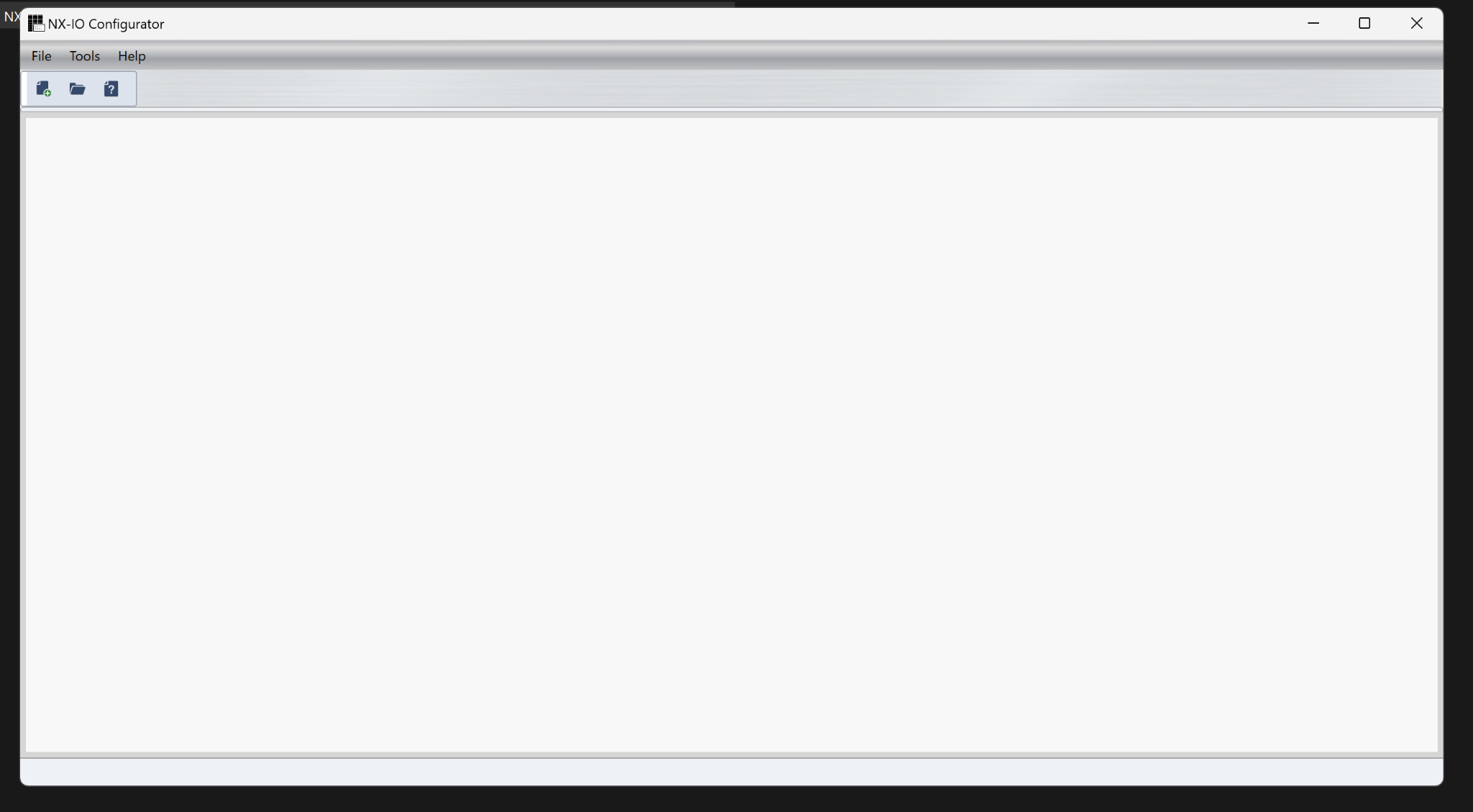
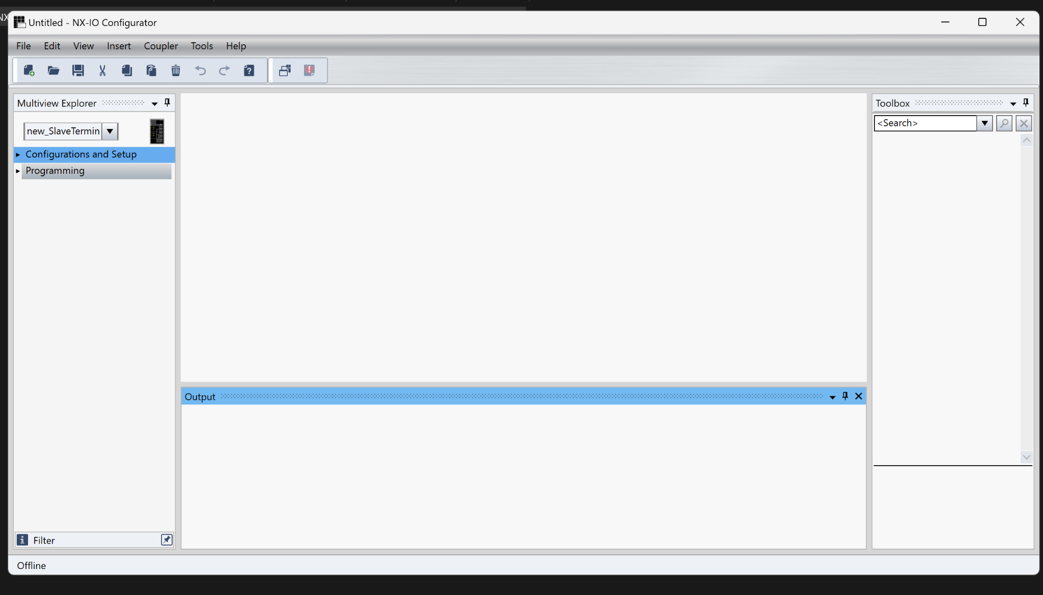
This is the initial screen of NX IO Configurator.
New Project
Create a new project by clicking File→Create new.
Enter a project name and click OK to proceed.
プロジェクト名を入力し、OKで進みます。
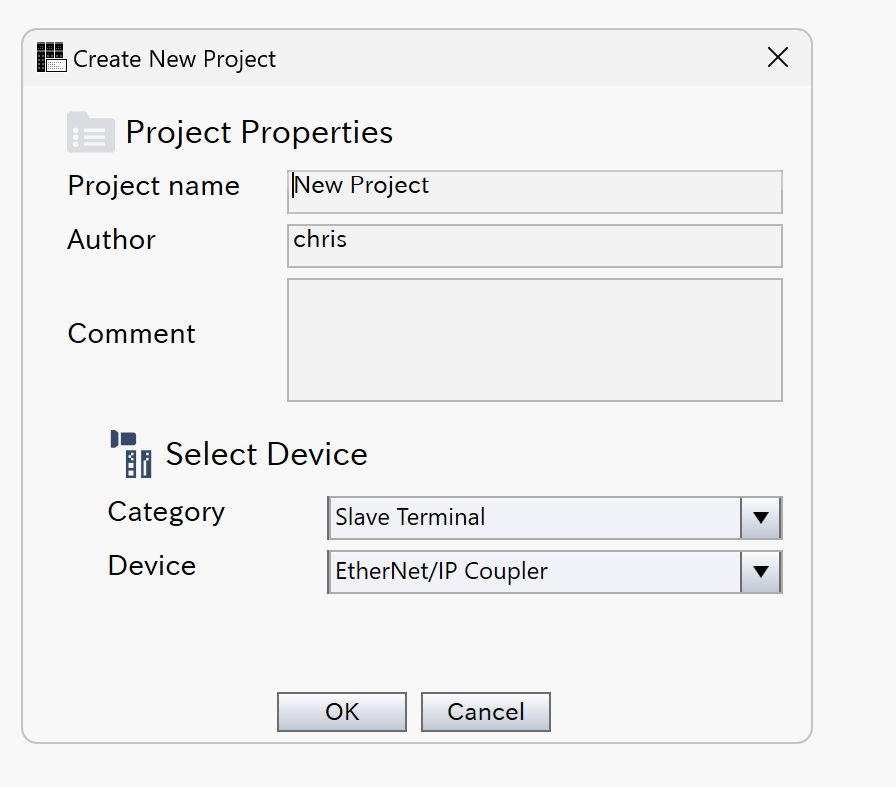
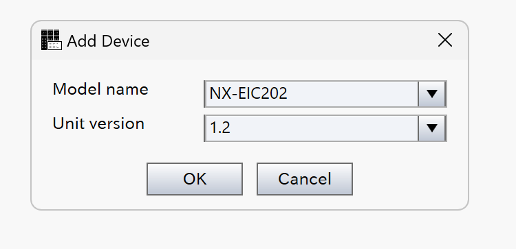
Select NX-EIC202 and click OK to proceed.
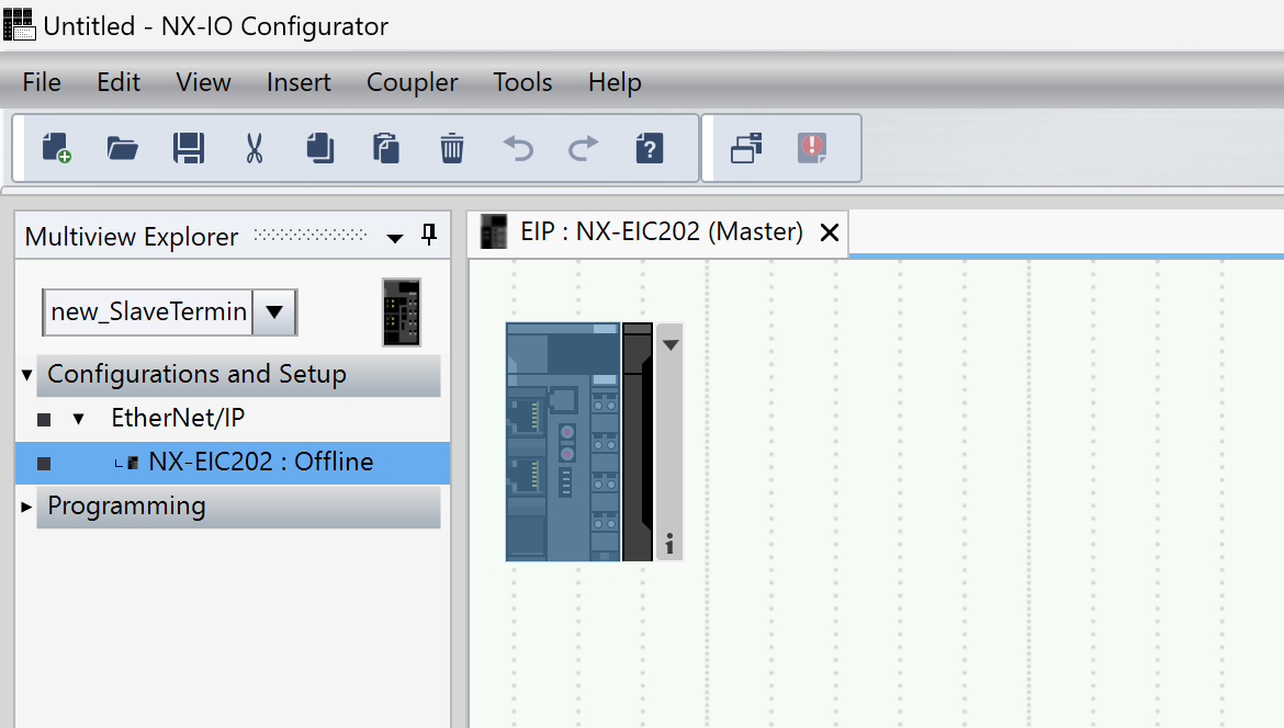
Done!
IO Module Settings
Now, add the IO modules installed next to the NX-EIC202.
Open Configuration and Setup→NX-EIC202.
Add the IO modules using the same operations as in Sysmac Studio.
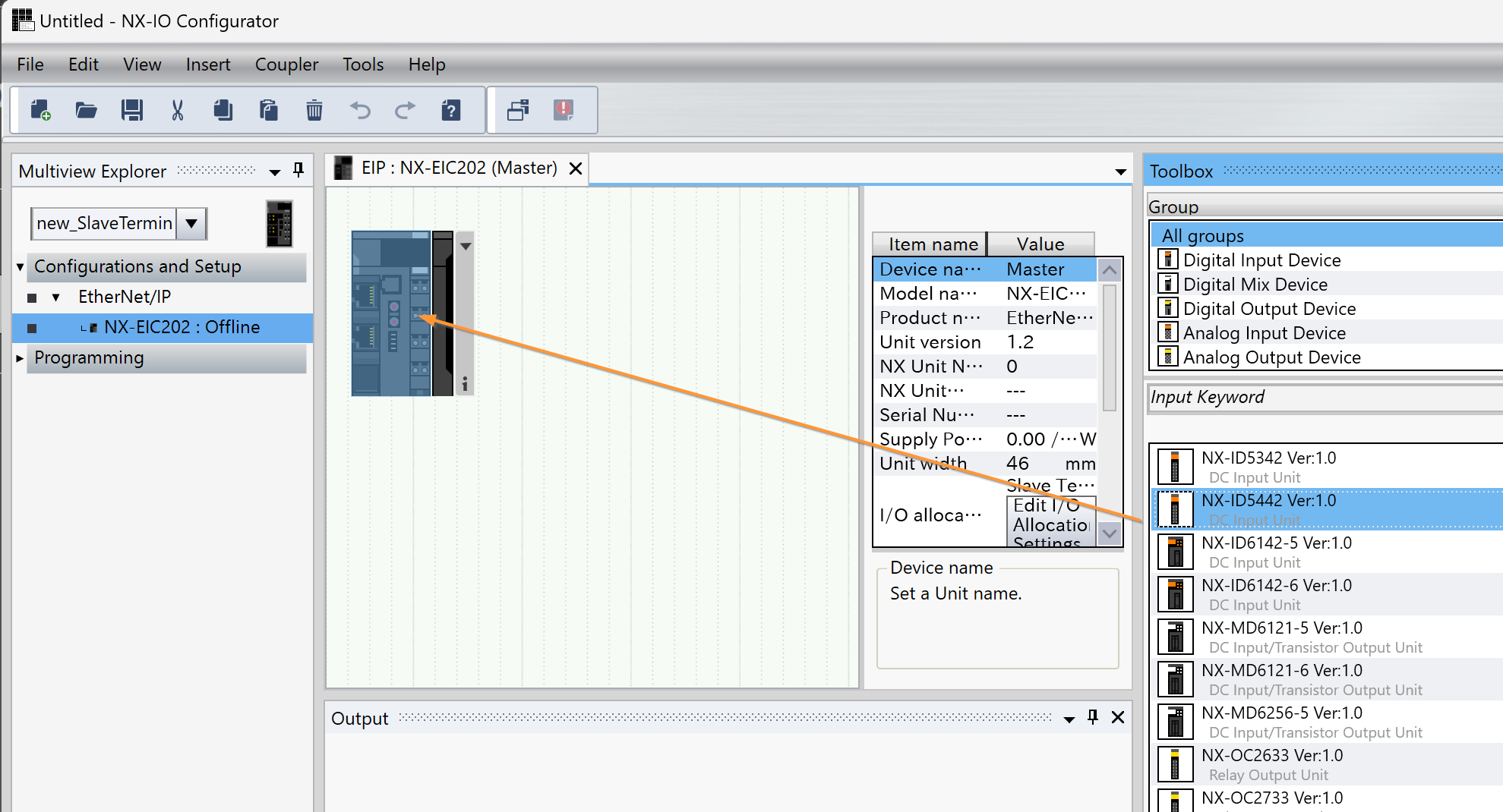
Done! In this article, we added 2 DI modules, 2 DO modules, and 1 AI module.
Online
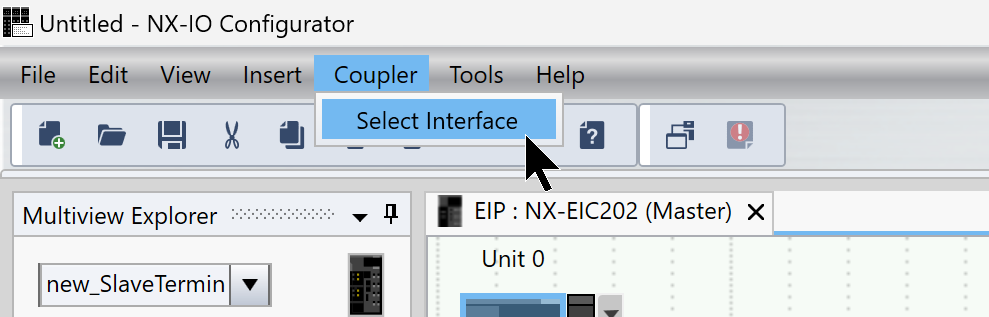
Next, to connect the PC and the EIC202 Ethernet/IP Coupler, go to Coupler→Select Interface.
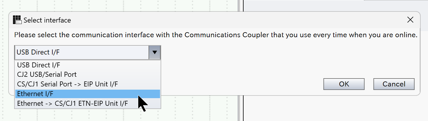
The connection interface setting screen will appear.
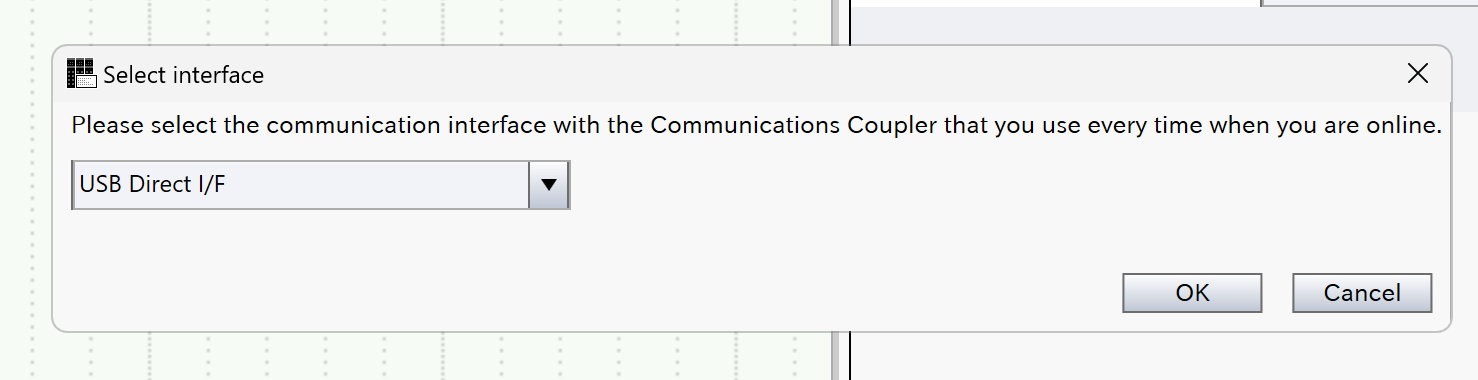
Select Ethernet I/F from the Drop-List and click OK to proceed.
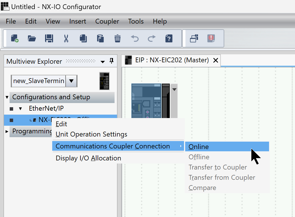
Next, right-click EIC202→Communication Coupler Connection→Online.
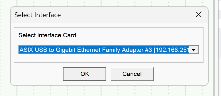
Set the Ethernet interface connecting the EIC202 and the PC, then click OK to proceed.
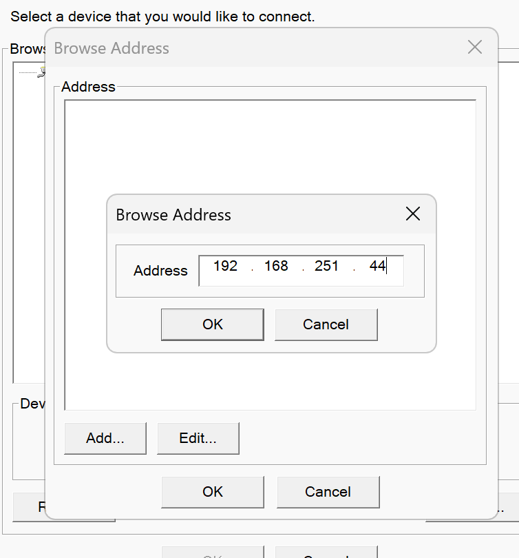
Enter the IP address of the EIC202 and click OK to proceed.
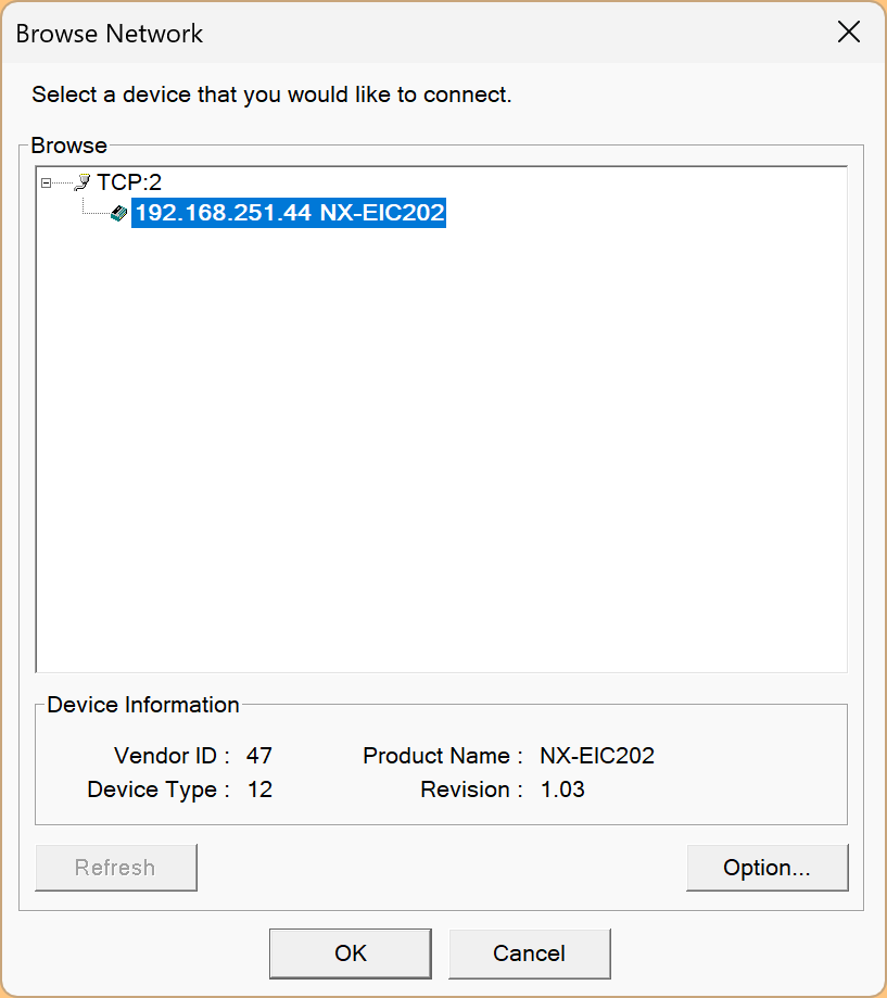
Done! The EIC202 has been found. Click OK to proceed.
The NX-IO Configurator and the PC are now connected.
Data Transfer
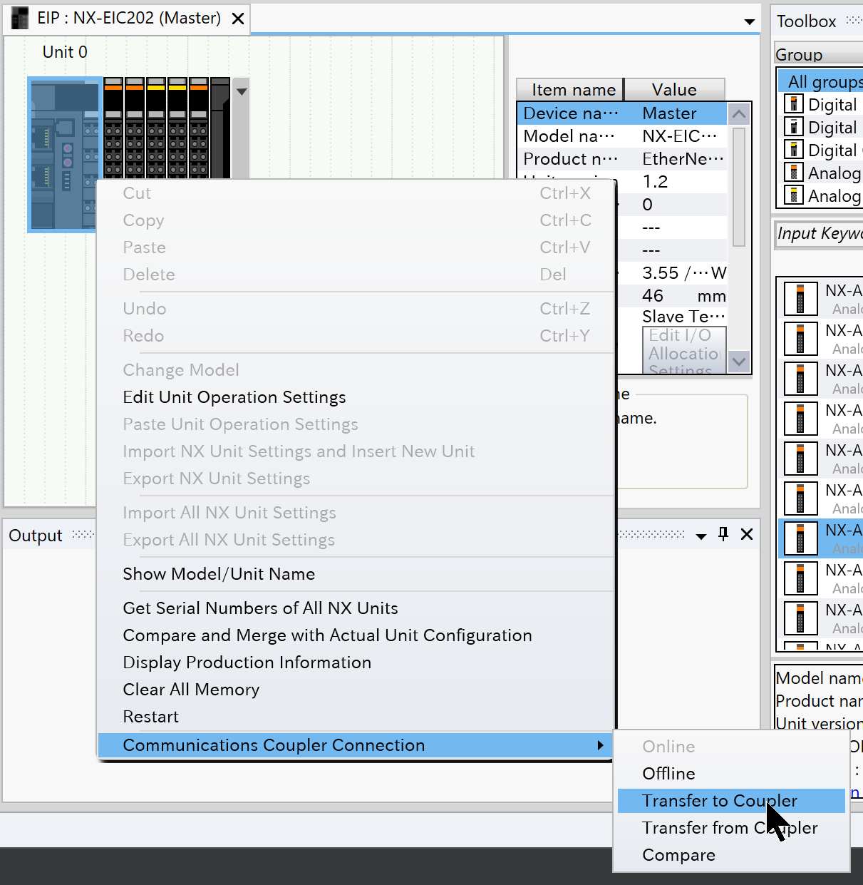
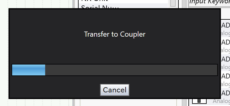
Next, click Communication Coupler Connection→Transfer to Coupler to download the coupler settings to the EIC202.
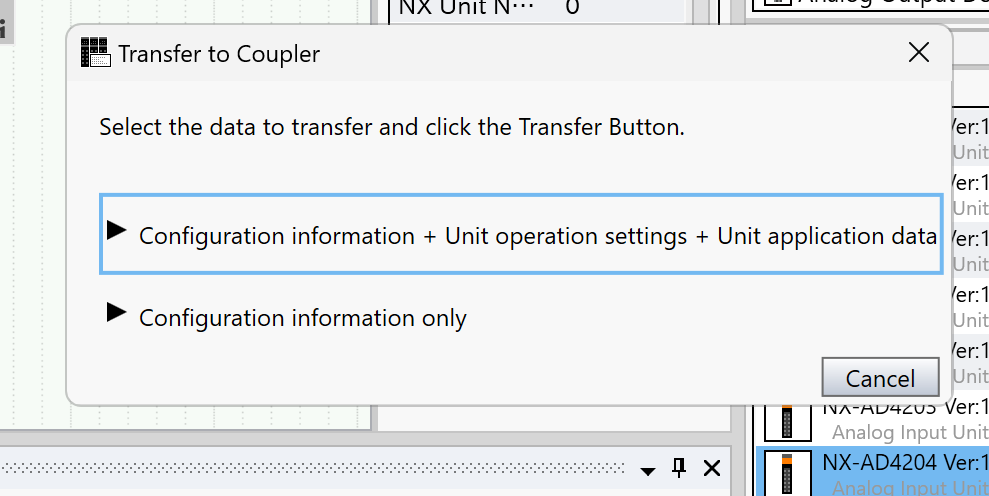
Download all data.
Click Yes to proceed.
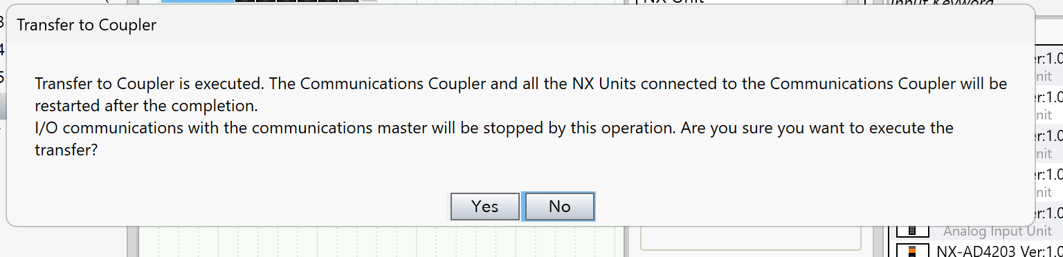
Please wait a moment…
IO Data Size
Finally, right-click NX-EIC202→Display I/O Allocation.
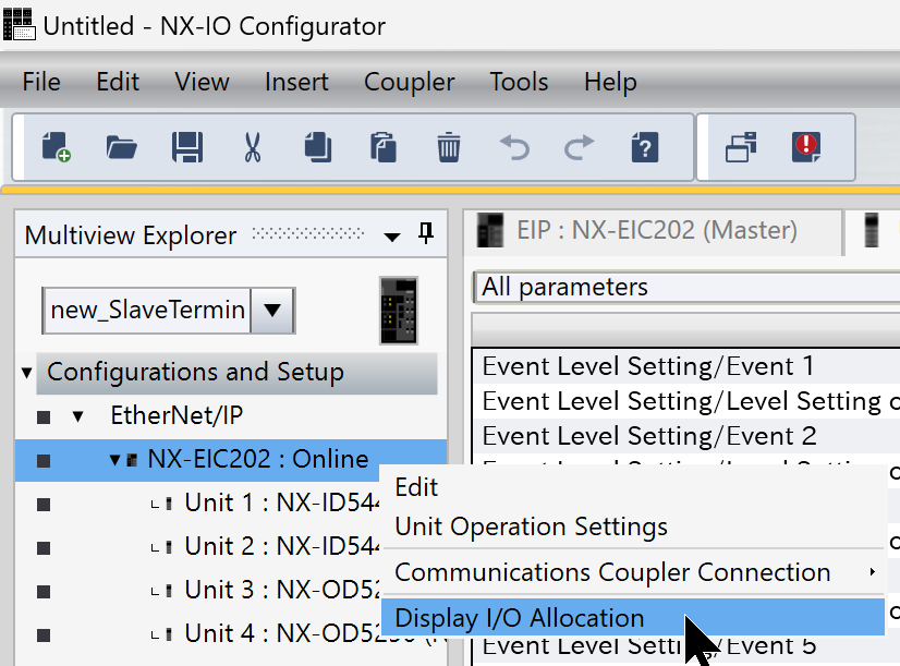
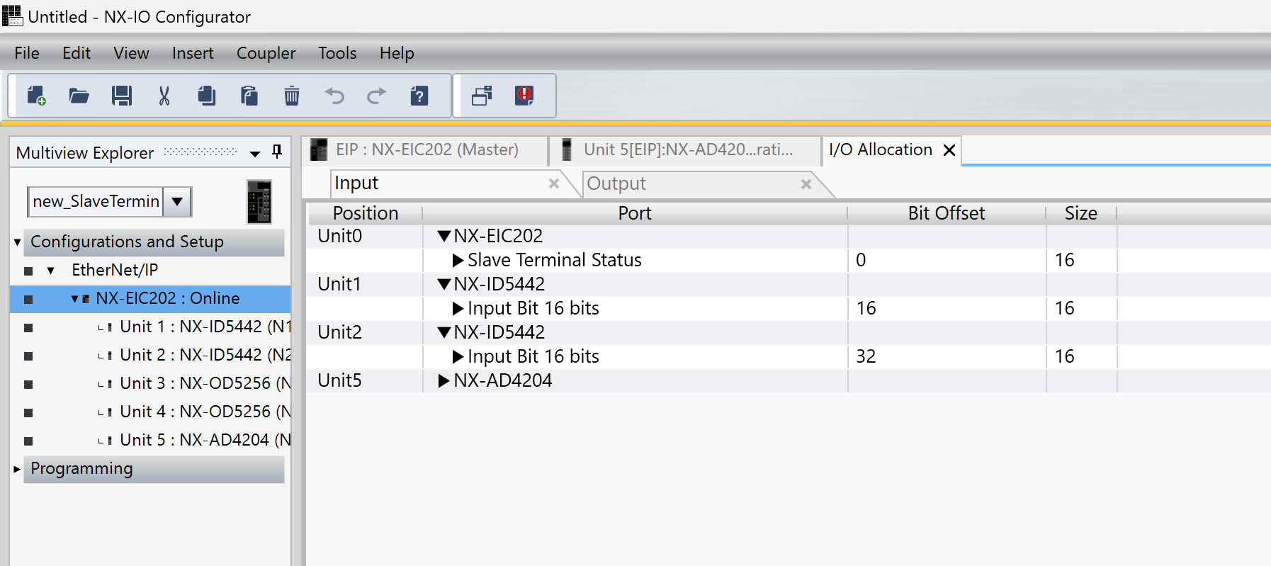
Here you can check the total occupied bytes for INPUT/OUTPUT data.
Codesys Side
Next, we will configure the Codesys side.
Import EDS
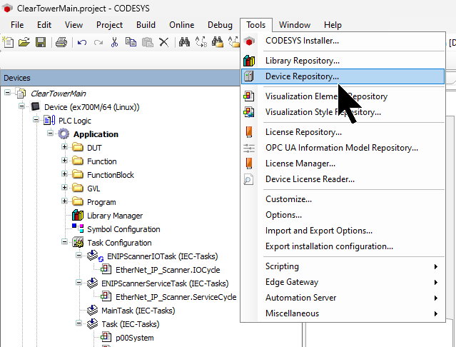
Click Tools→Device Repository.
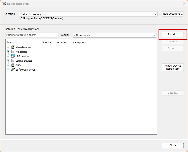
Click Install.
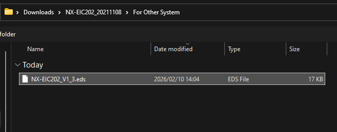
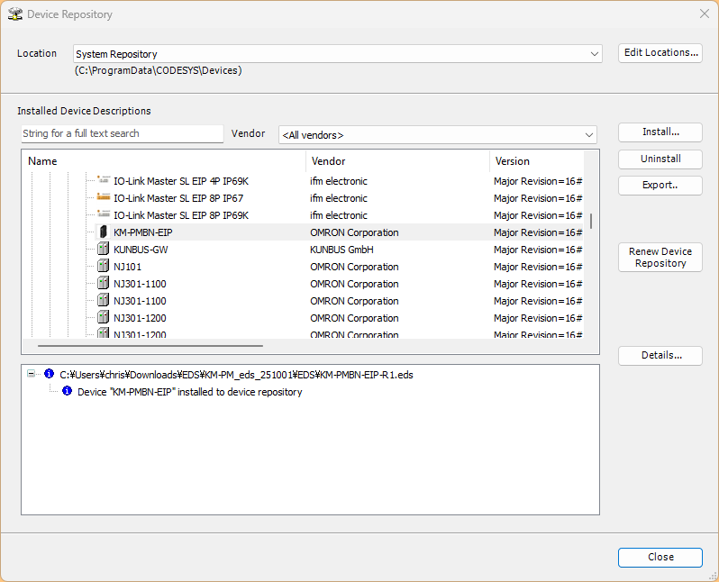
Install the EDS FILE you downloaded earlier.
Done!
Add Ethernet Interface
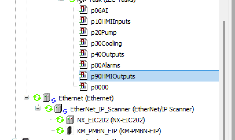
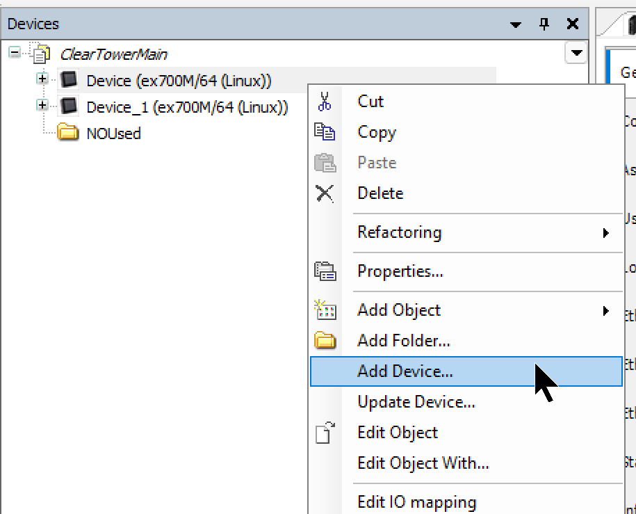
Right-click Device→Add Device.
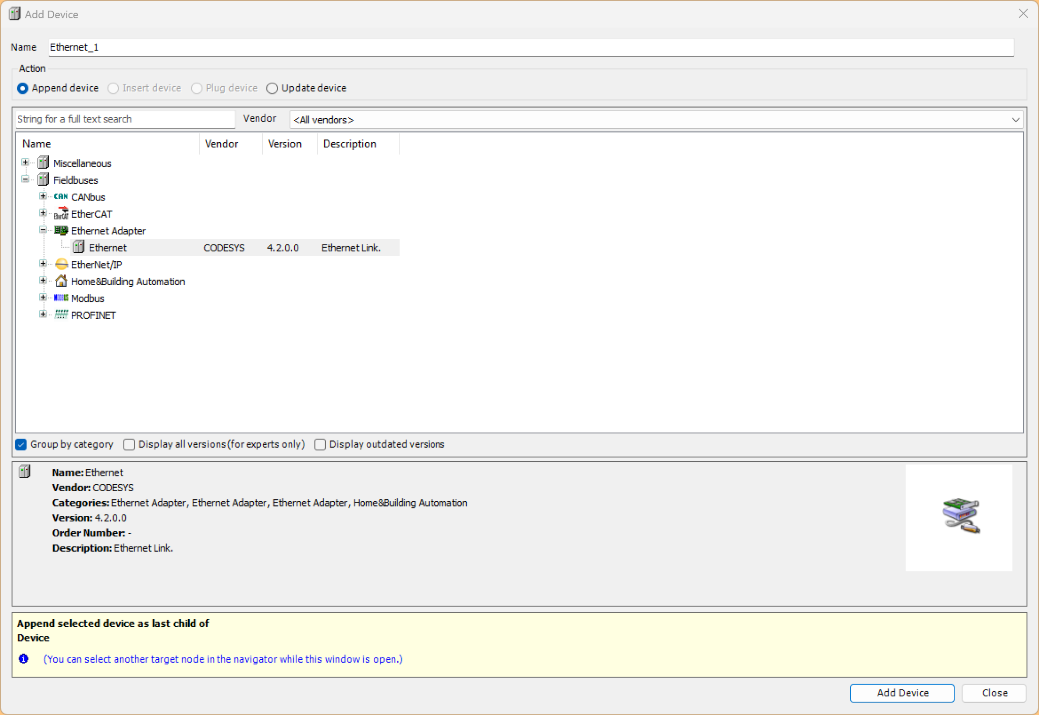
Click Ethernet Adapter→Ethernet to add the Ethernet interface.
Add Ethernet/IP Scanner
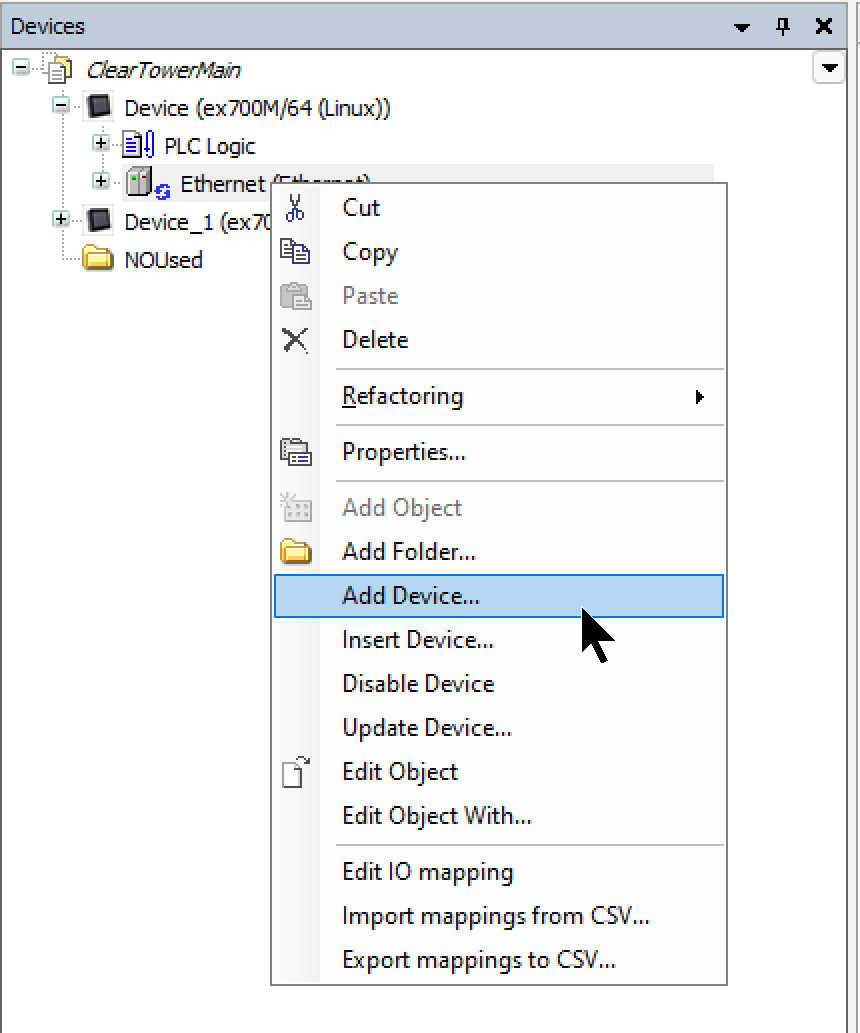
Next, right-click the Ethernet interface and select Add Device.
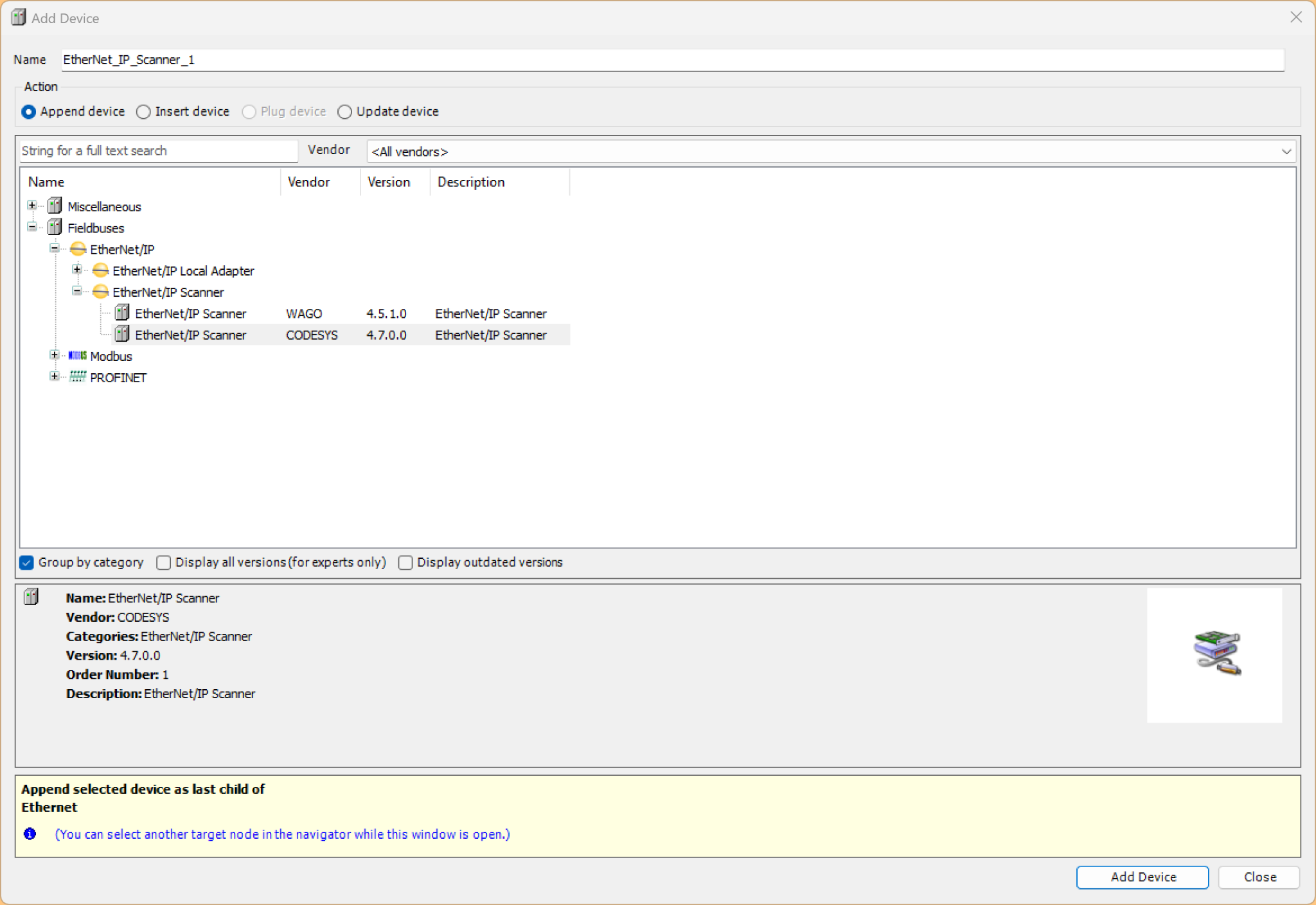
Select Ethernet/IP Scanner and click Add Device.
Add Device
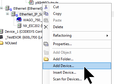
Finally, to add the Omron EIC202 used in this article, right-click Ethernet/IP Scanner→Add Device.
Select Omron IEIC202 and click Add Device.
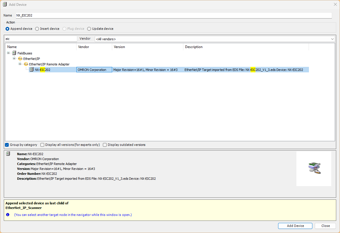
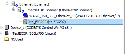
Done!
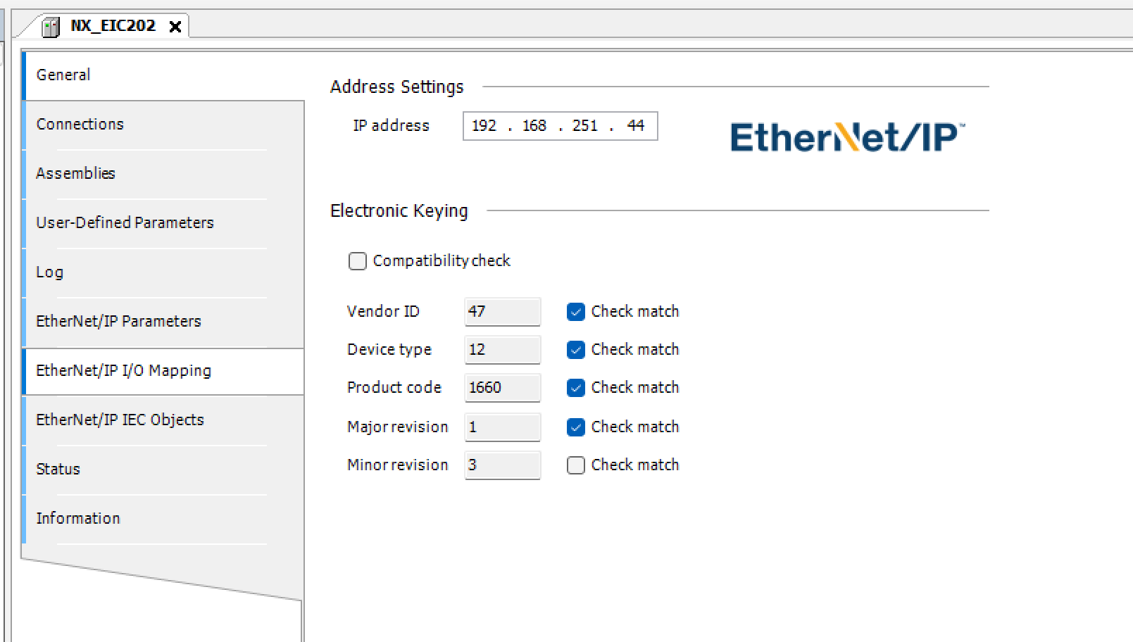
IP Address
Set the IP address of the Omron EIC202 according to your network configuration.
Connection Settings
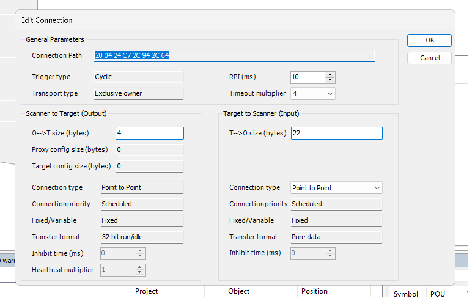
Next, open the Connection Tab and click Edit Connection.
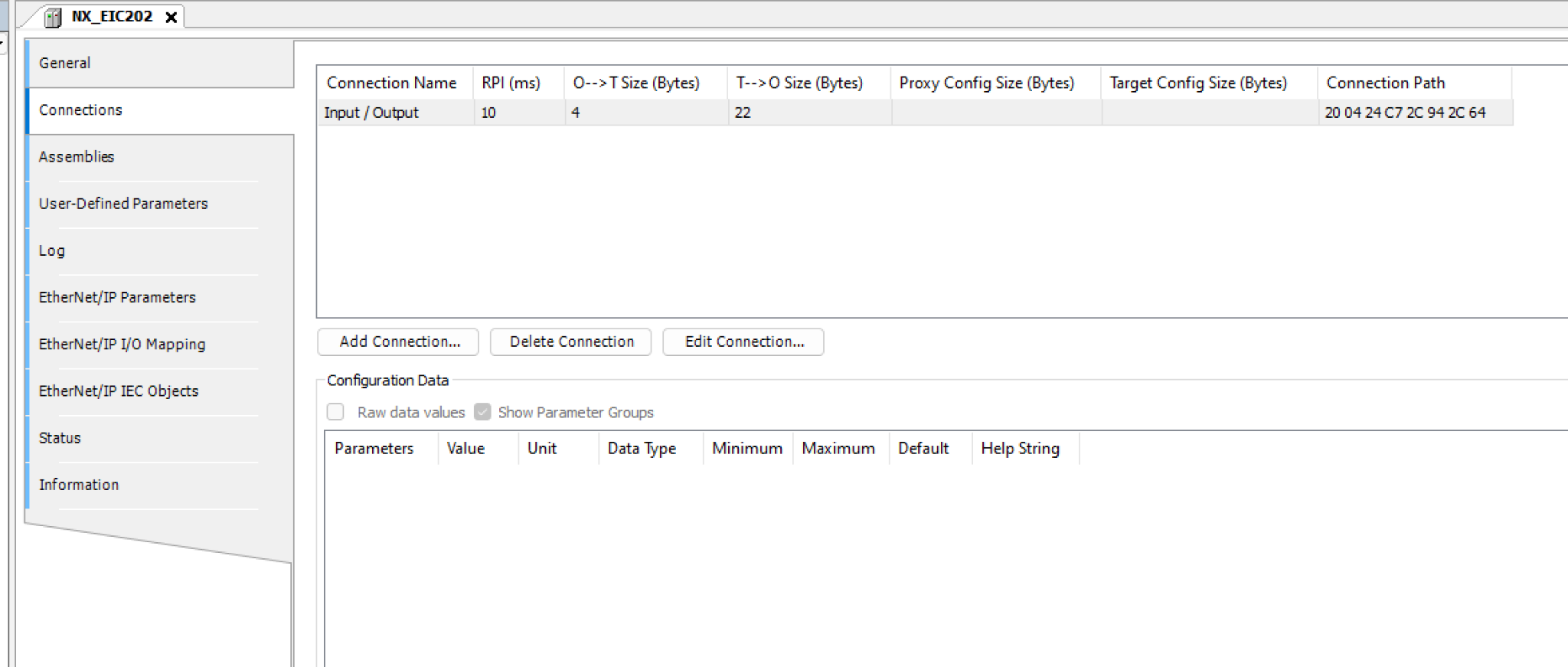
Set the occupied byte count for O-> T Size (Output) and T->O Size (Input) data.
As seen previously in NX-IO Configurator:
- 2 modules of 16-point DO output = 4 Bytes (O-> T)
- 2 modules of 16-point DI input + 1 module of 8-point AI input + module status = 22 Bytes (T->O)
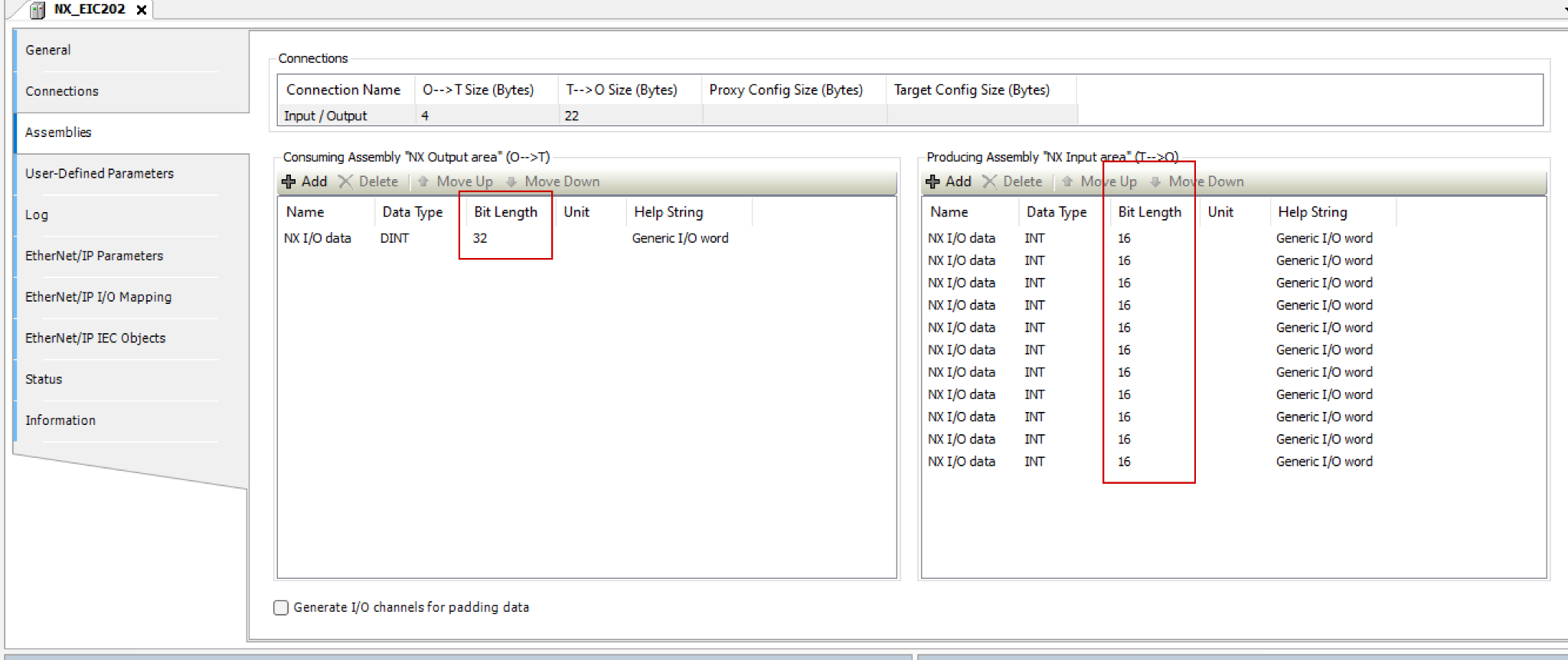
Next, open the Assemblies Tab and add new Assemblies for O->T and T->O with the number of Tags matching the byte counts set earlier. In the figure below:
- O->T=4Byte=DINT=32Bit Length
- T->O=22Byte=INT=16Bit Length x11 units
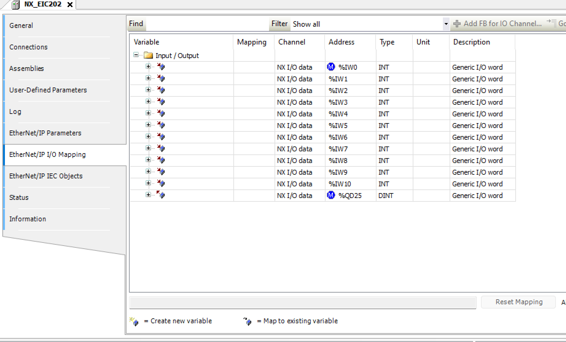
Mapping
Finally, we have the address settings. Since Omron’s EIC202 is divided into various connection items, setting the addresses at the beginning will make GVL Mapping easier.
GVL
Next, create a GVL and define variables using the structures created earlier. Also, use the AT keyword to map them to the specified addresses.
{attribute ‘qualified_only’}
|
|---|
Results
Done! We have successfully established an Ethernet/IP connection between Codesys Runtime and the Omron EIC202.