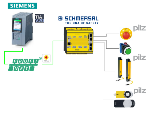
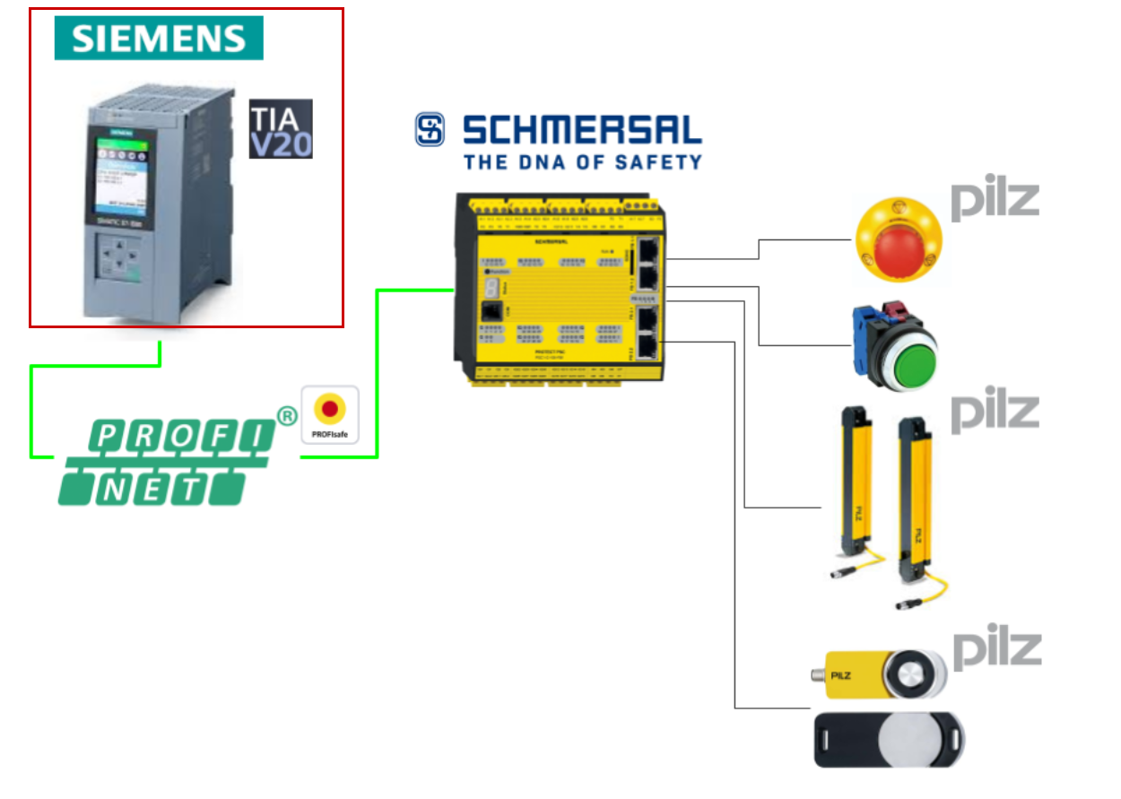
This is a new series where we will be developing various articles using Schmersal’s PSC1-C-100-FB1 Safety Controller. In Episode 8, we will exchange data with the Siemens S71500F via Profinet and Profisafe. Additionally, TIA V20 will be used throughout the article.
Now, let’s enjoy FA.
Reference Video
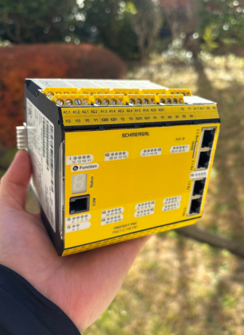
Schmersal.PSC1-C-100-FB1 開封しました!
Reference Link
http://soup01.com/ja/category/schmersal_jp/psc1/
Implementation
Here is the structure of this article.
Schmersal Side
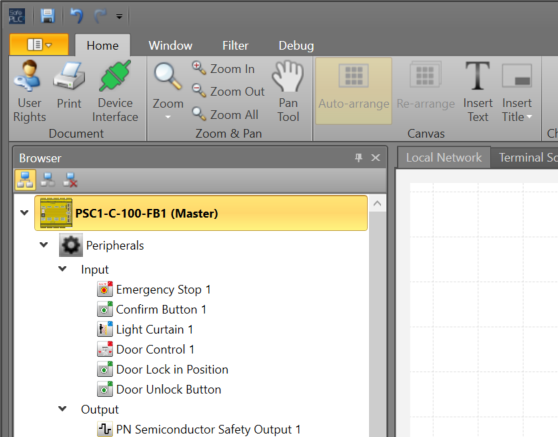
First, we will build from the Schmersal side.

Configure Fieldbus
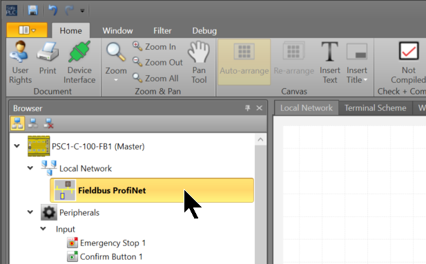
Click on the controller to enable the Profisafe Interface on the PSC1-C-100-FB1 Safety Controller.
Check the Fieldbus checkbox under Local Network in the Properties screen.
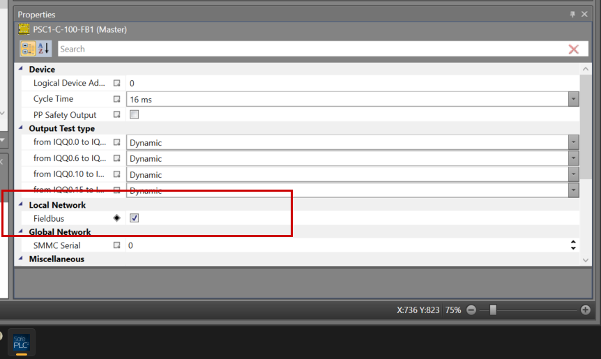
The Fieldbus display will be added to the Local Network tab of the project.
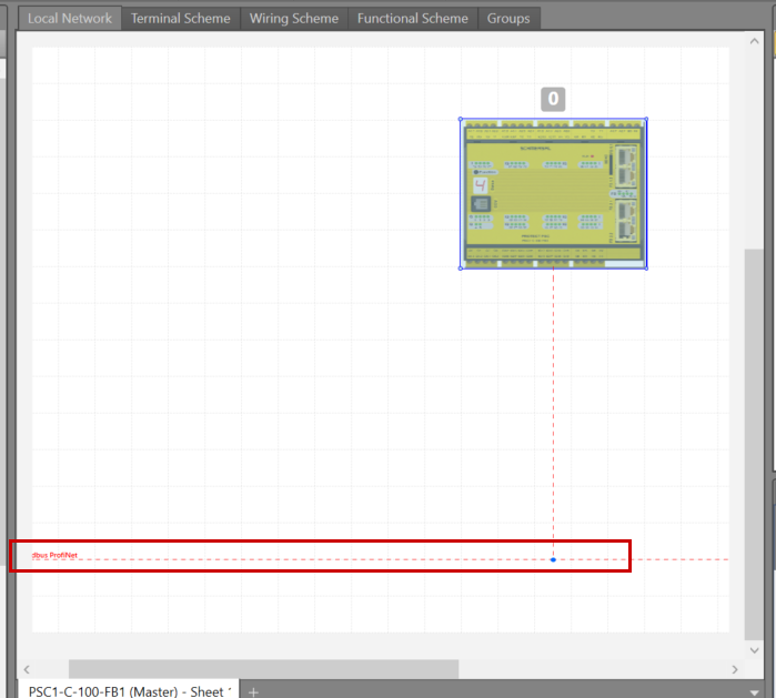
Next, click Local Network>Fieldbus.
Set Profinet in Properties>Network>Type.
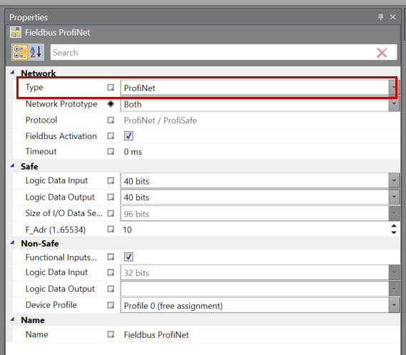
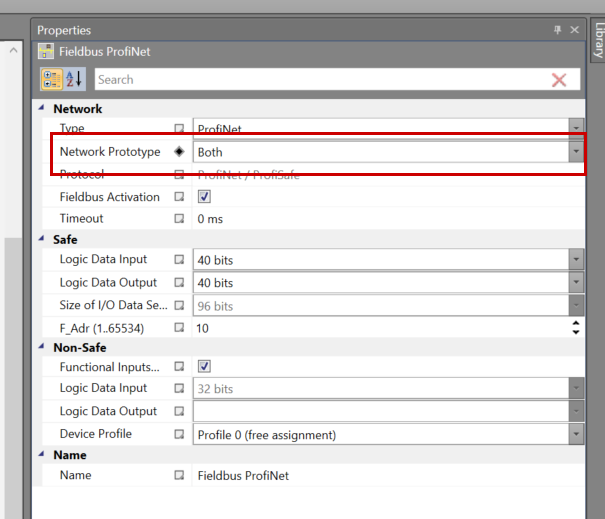
Since both Profisafe and Profinet will be used in this article, please set the Network Prototype to “Both”.
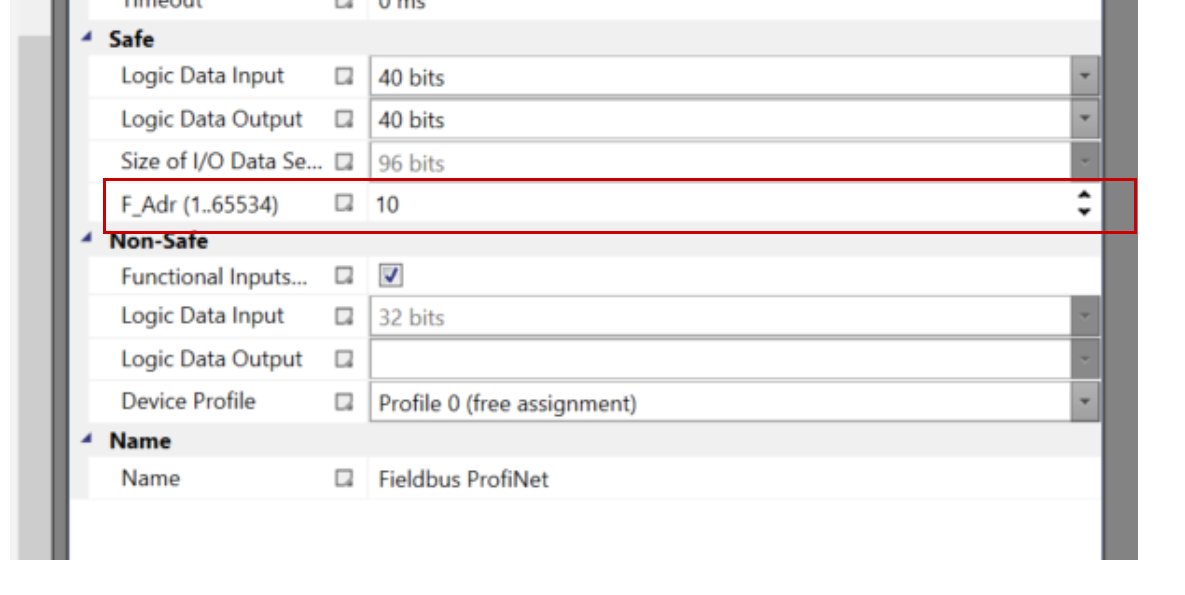
F-Address
Set the F-Address for the PSC-C-100-FB1, and let’s match it in TIA later.
Safety Program
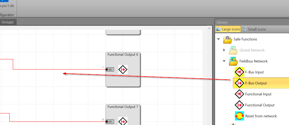
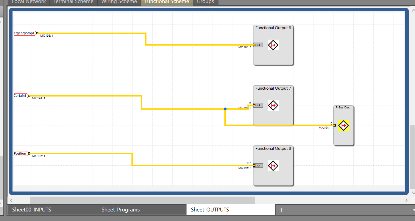
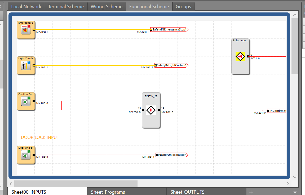
Next, we will create the safety program. This article follows from Part 7 and adds safety communication. Add Fieldbus Network>F-Bus Output to the Function Sheet.
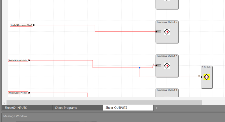
This time, connect the F-Bus Output to the Light Curtain output.
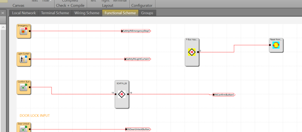
And a safety reset is also possible from the Siemens Profisafe signal.
Connect to the Controller
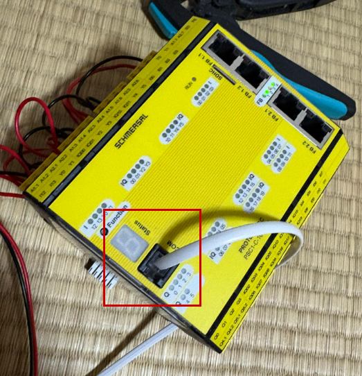
Connect the PSC1-C-100-FB1 COM Port to the PC using the dedicated cable.
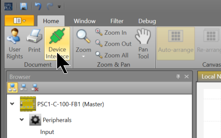
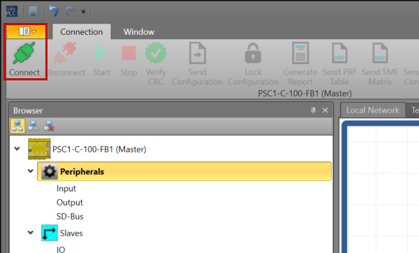
Click SafePLC2>Home>Device Interface.
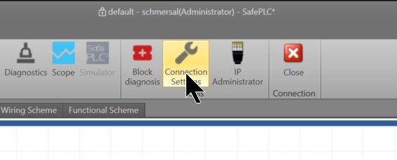
Click Connection Settings.
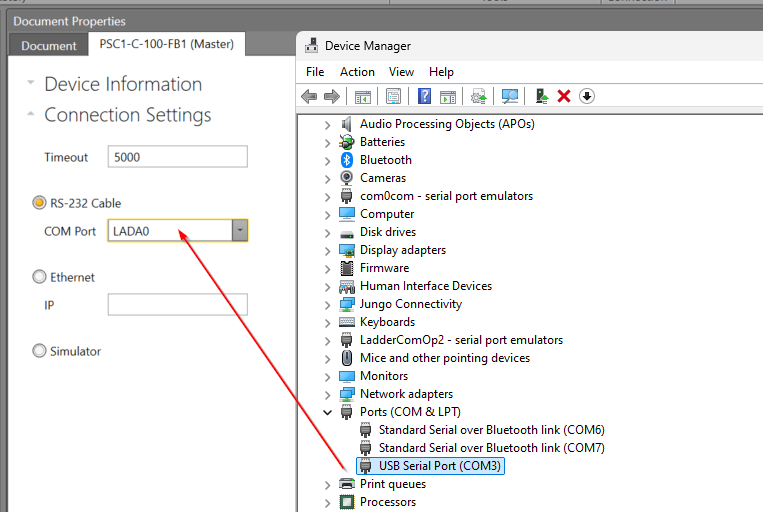
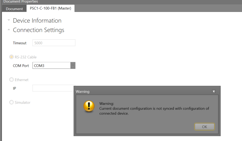
Since we are using an RS-232 cable this time, set the COM Port according to the Device Manager.
Finally, click the Connect button to connect the CPU and SafePLC2.
Proceed with OK. With this, the connection between SafePLC2 and PSC1-C-100-FB1 is established.
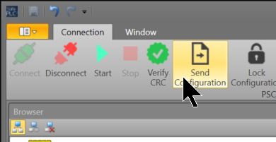
Send Configuration
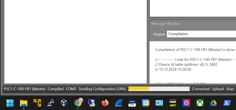
Click Send Configuration to transfer the project to the PSC1-C-100-FB1.
Please wait a moment…
Siemens Side
Next, we will create the Siemens side.
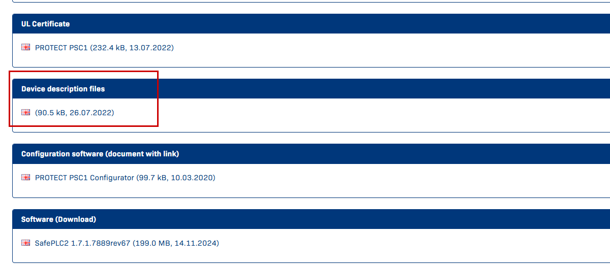
Download GSDML File
To build the Profinet/Profisafe network, please download the GSDML from Schmersal’s website.
https://products.schmersal.com/en_IO/psc1-c-100-fb1-103008452.html
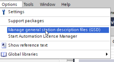
Install GSDML File
Click Options>Manage general Station description files (GSD).
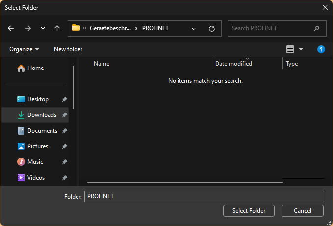
The GSDML management screen appears; click the … button.
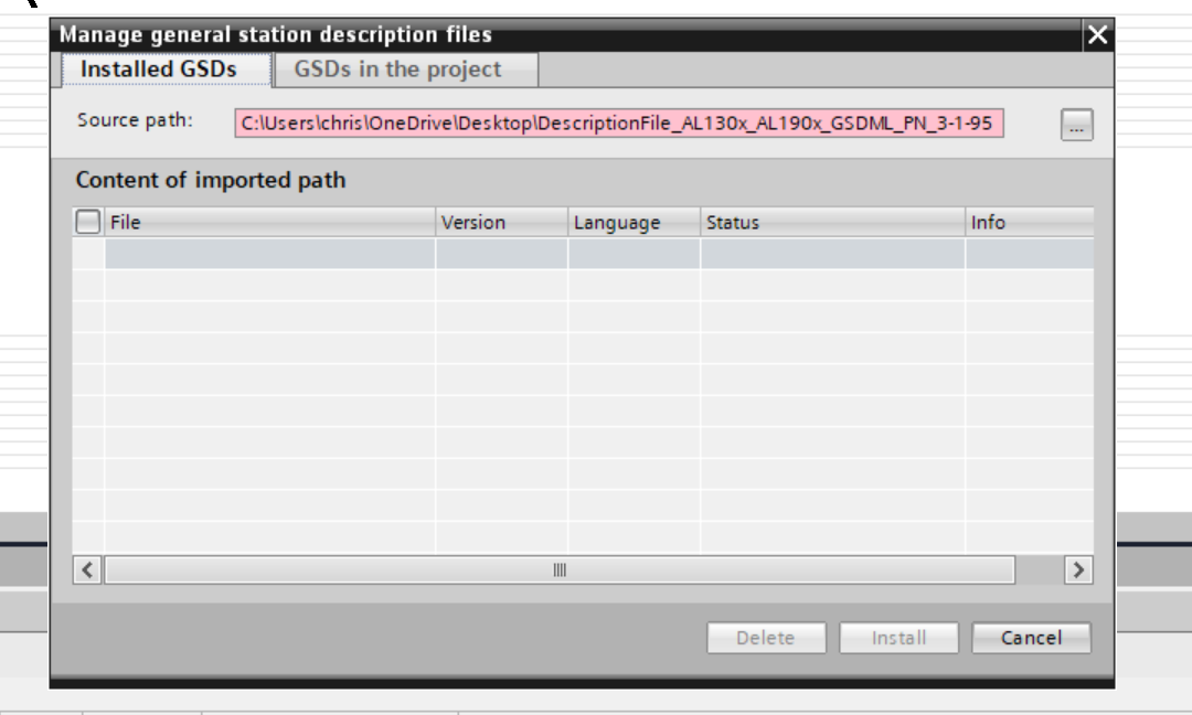
Select the GSDML Folder you just downloaded.
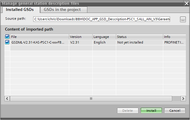
Done! The GSDML File was found. Install the GSDML File with Install.
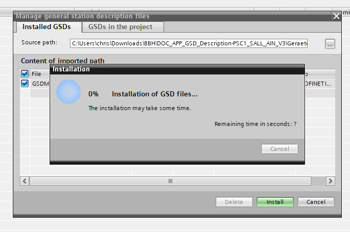
Please wait a moment.
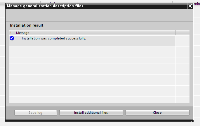
Done!
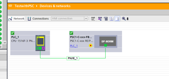
Configure Profinet Network
Next, build the Profinet Network.
Add PSC
Add the Schmersal PSC-C-100-FB1 controller to the Profinet network.
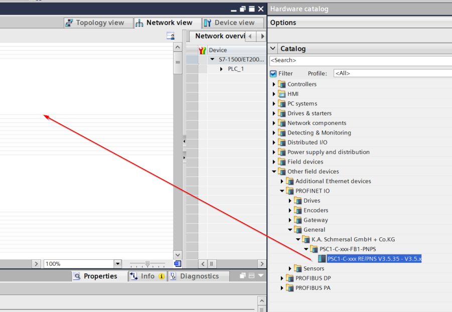
Done!
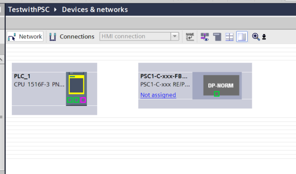
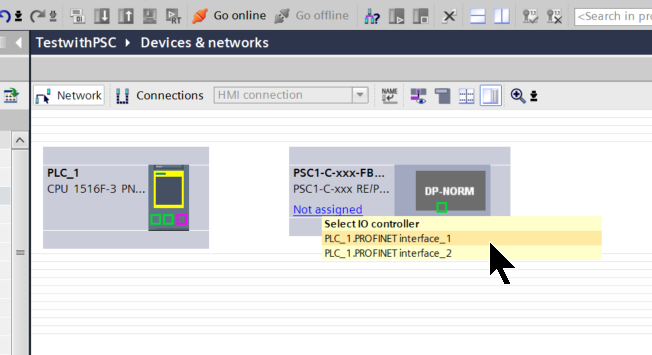
Assign Profinet Network
Click on “Not assigned” for Schmersal PSC-C-100-FB1 and set the appropriate Profinet interface.
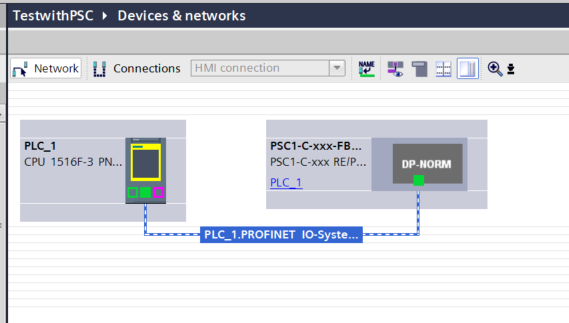
Done!
Configure IP Address
Next, click Show address labels to set the IP address for each Profinet device.
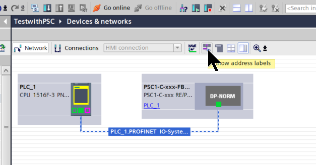
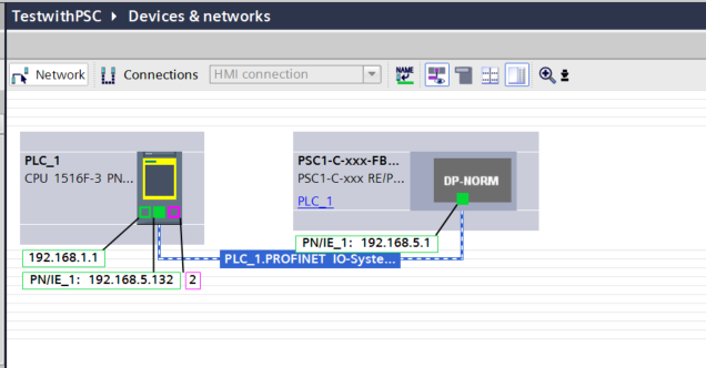
The IP addresses for each Profinet device are displayed, so set them according to the application.
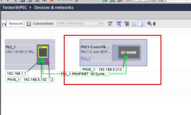
Configure PSC1
Double-click the PSC-C-100-FB1 to configure the Schmersal PSC-C-100-FB1 safety controller.
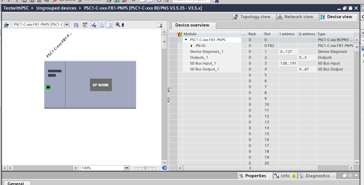
Insert Profisafe Slot
Since we are using Profisafe communication in this article, add Module>F Module IO (12 Bytes) to Slot 5.
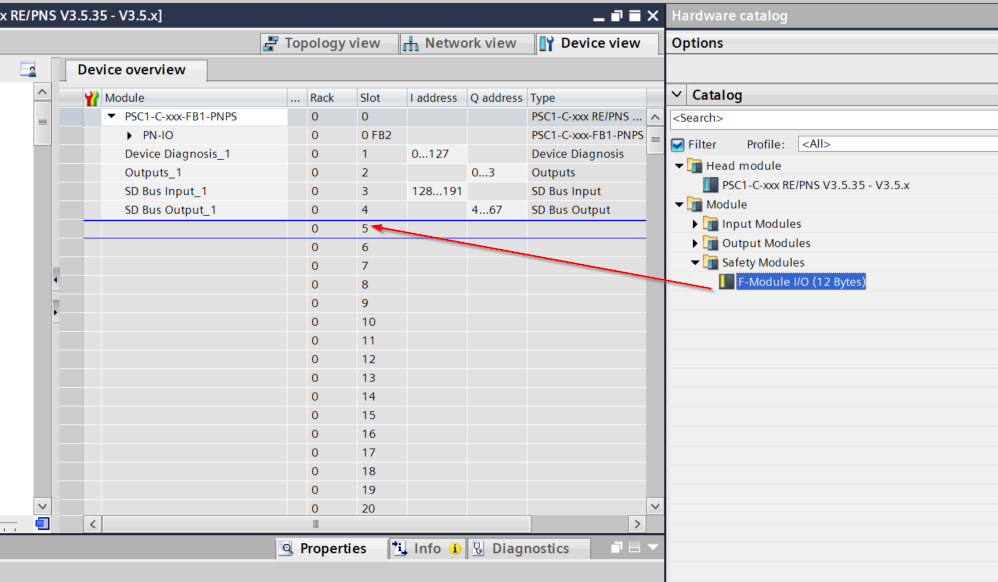
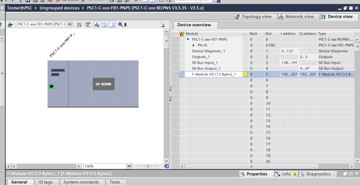
Done!
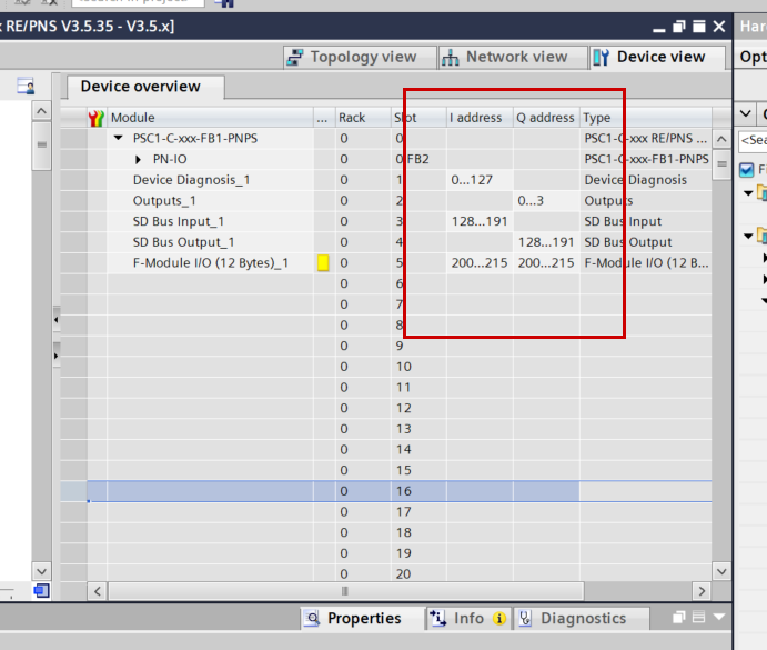
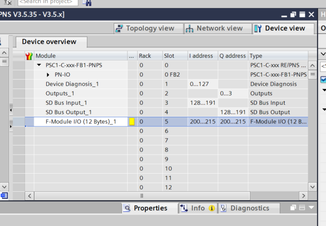
Adjust the IO Address
Adjust the IO numbers of the data exchanged by the PSC-C-100-FB1 via Profinet.
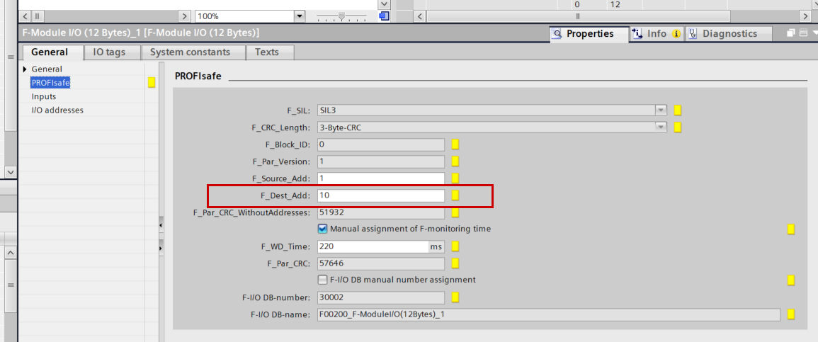
Configure Profisafe
Next, click the F-Module previously added to Slot 5 to change the Profisafe connection for the PSC-C-100-FB1.
The F-Address was previously set to 10.

Set PROFIsafe>F_Dest_Add to 10.
DUT
Define structures to match the data exchange between PSC-C-100-FB1 and S71500F.
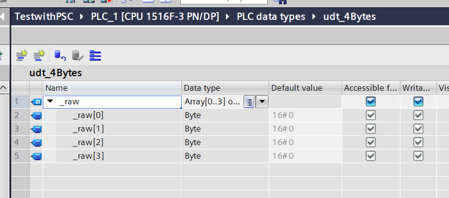
udt_4Bytes
This is a 4-byte structure.
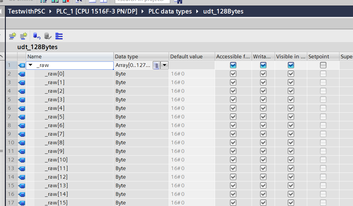
udt_128Bytes
This is a 128-byte structure.
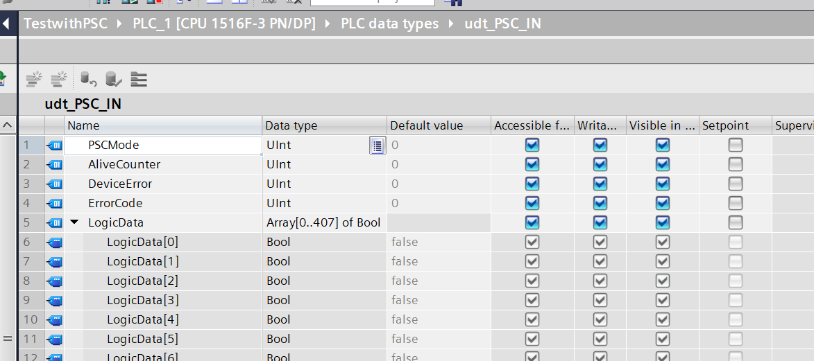
udt_PSC_IN
This structure was created to match the input data of Schmersal’s PSC-C-100-FB1.
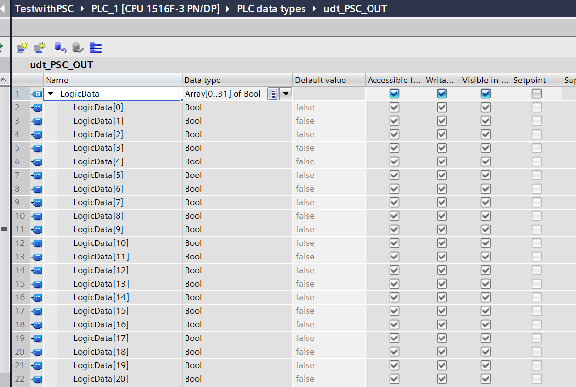
udt_PSC_OUT
This structure was created to match the output data of Schmersal’s PSC-C-100-FB1.
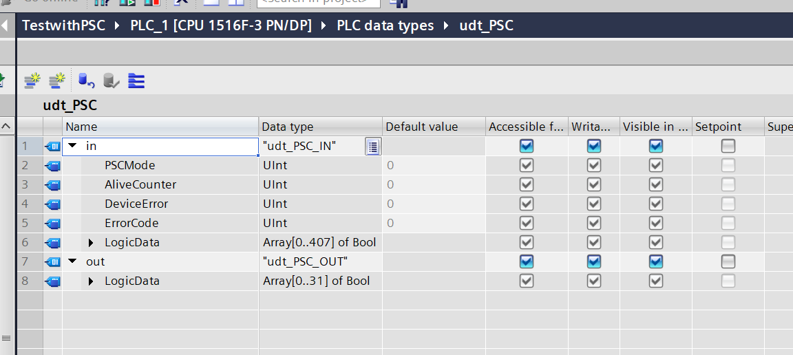
udt_PSC
Finally, let’s define a structure that combines those defined previously.
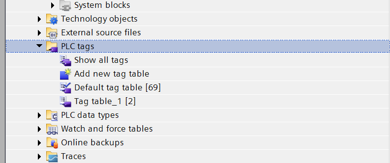
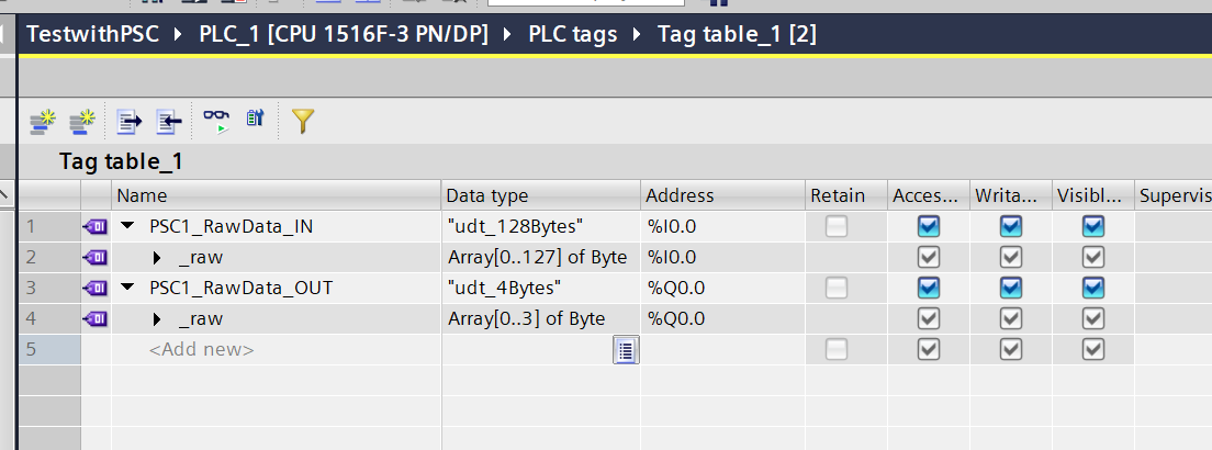
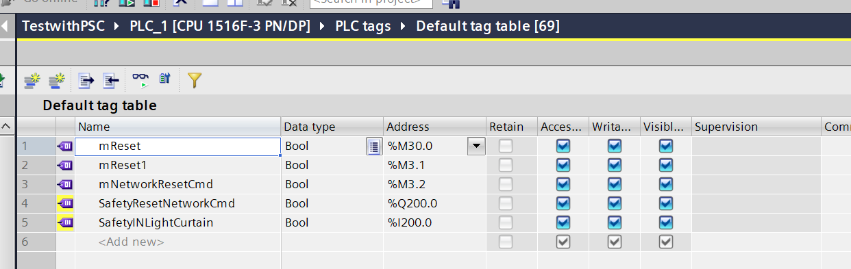
Tags
Create PLC Tags to build the program.
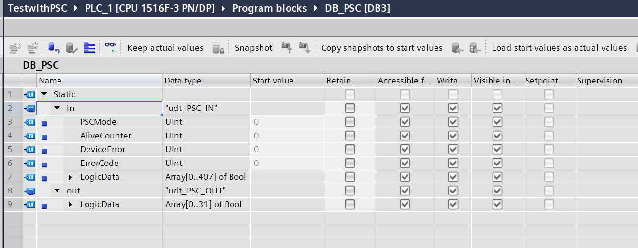
DB
Declare the DB based on the structure created previously.
Function Block
Next, create the Function Block.
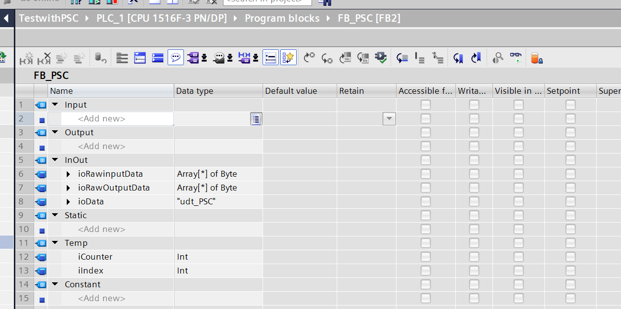
FB_PSC
This FB implements a function to expand data received from or sent to the PSC-C-100-FB1 via Profinet into structures.
VAR
This is the FB interface. Only Inout is defined, with 3 parameters.
- Byte array with no specified length
- The PSC-C-100-FB1 structure defined earlier
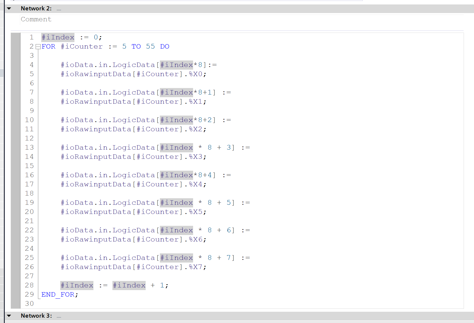
Network 2
Network 2 decomposes the data received from the PSC-C-100-FB1 into the Bool array in the structure.
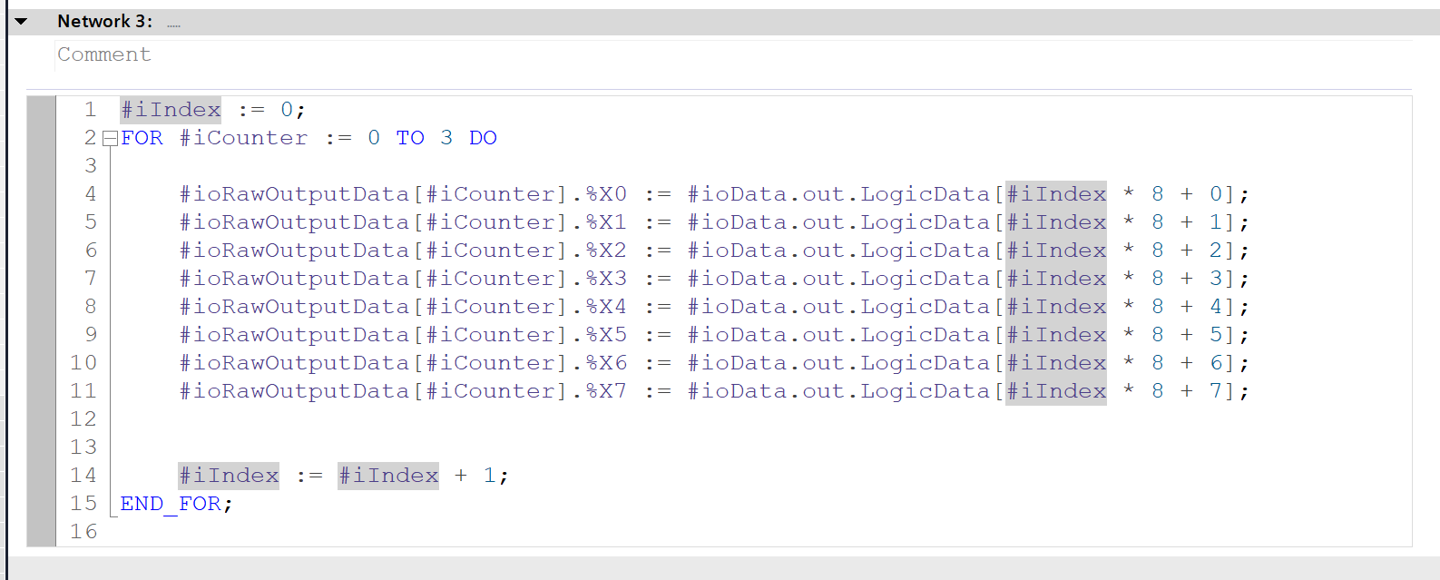
Network 3
Network 3 is a program that outputs the Bool array in the structure to the PSC-C-100-FB1.
FB_Station
This FB expands the data decomposed in FB_PSC into meaningful variables.
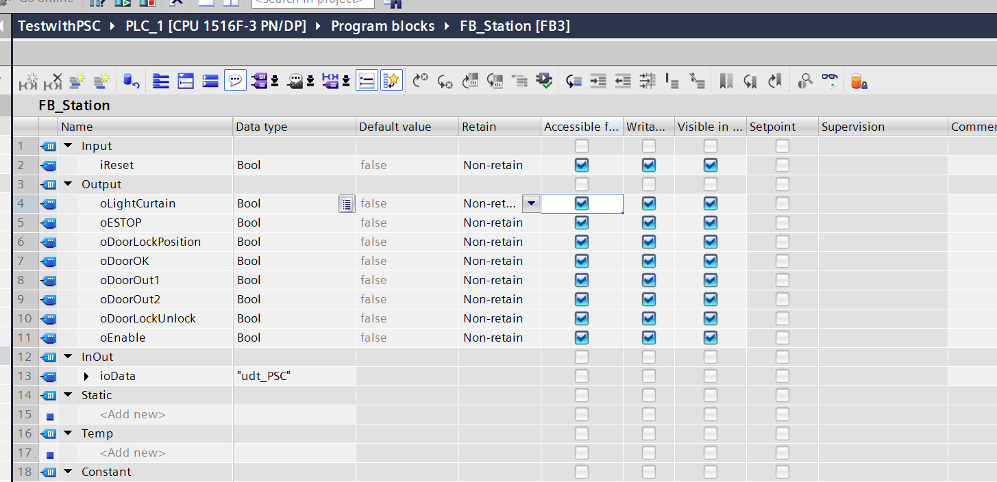
VAR
This is the FB_Station interface.
- iReset: Bit for reset permission sent to PSC-C-100-FB1.
- oESTOP etc.: Variables expanded from data received from PSC-C-100-FB1.
- ioData: Structured variable decomposed in FB_PSC.
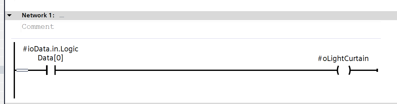
Network 1
LogicData Bit 0 received via Profinet represents the status of the Light Curtain.
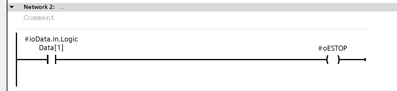
Network 2
LogicData Bit 1 received via Profinet represents the status of the Emergency Stop.
Network 3
LogicData Bit 107/Bit 407/Bit 16/Bit 402/Bit 250 received via Profinet represent the status of the door locks.
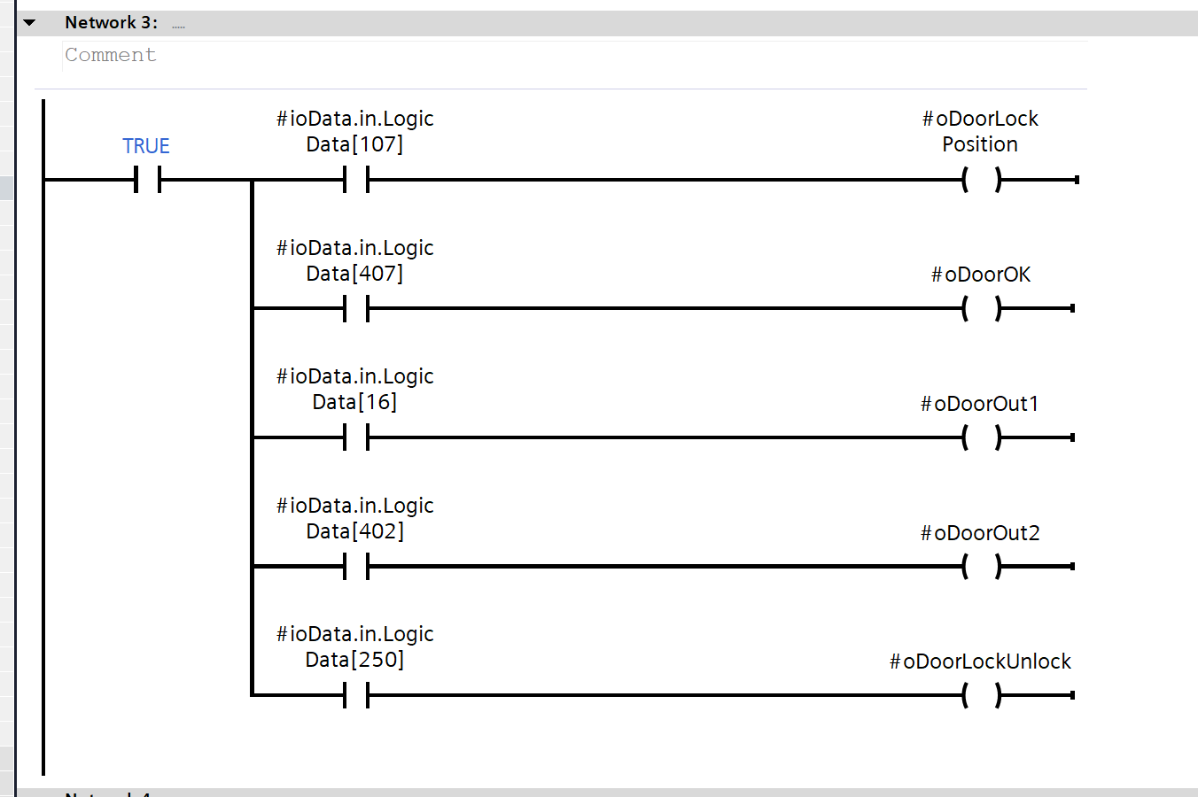
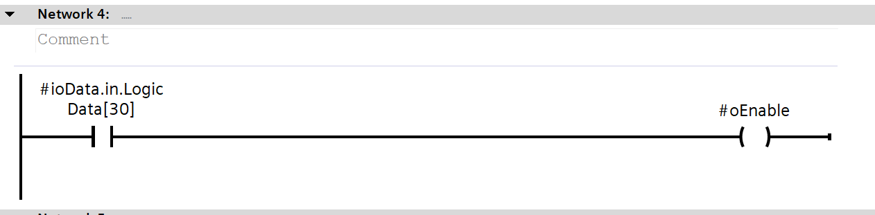
Network 4
LogicData Bit 30 received via Profinet is a signal indicating that all safety devices are normal.
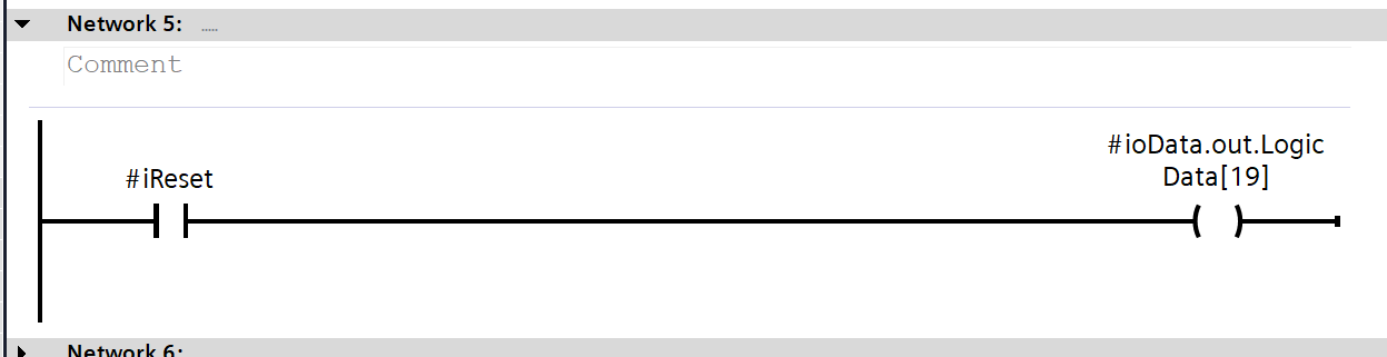
Network 5
LogicData Bit 19 sent via Profinet is the reset permission signal.
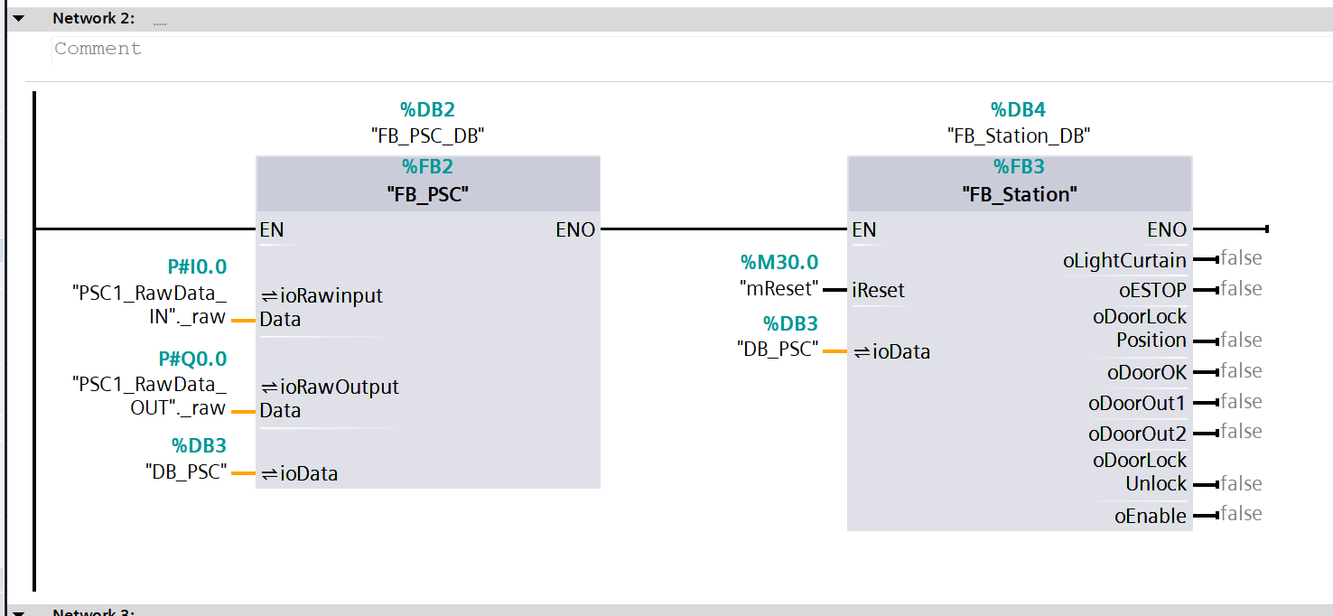
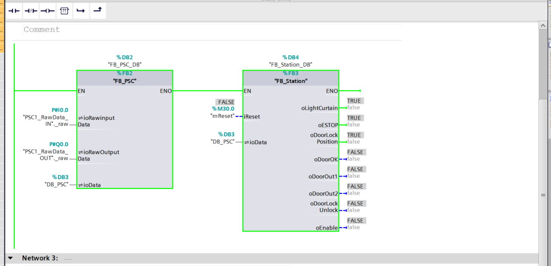
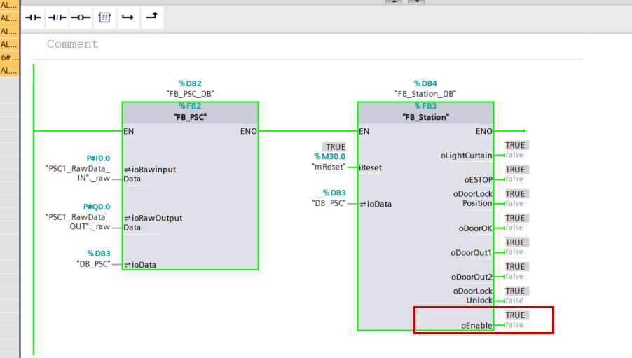
OB1
Next, call the created FB in OB1 and assign the appropriate tags.
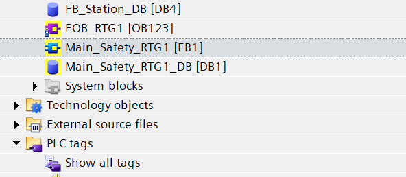
Safety Program
Now, we will create the safety program.
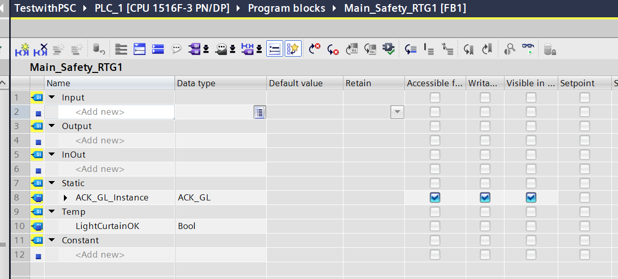
VAR
This is the Instance variable defined in Safety FB1.
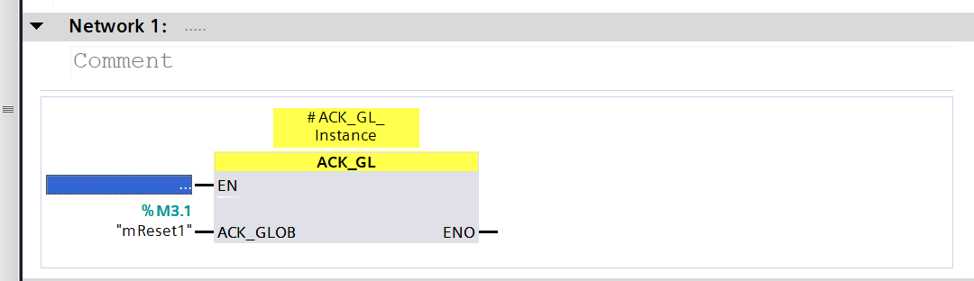
Network 1
Network 1 calls the FB that resets the Profisafe network.
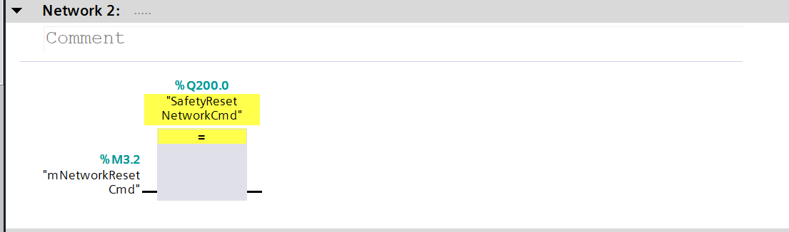
Network 2
In Network 2, the S71500F sends a SafetyNetwork reset command to the PSC-C-100-FB1 via Profisafe.
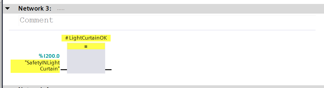
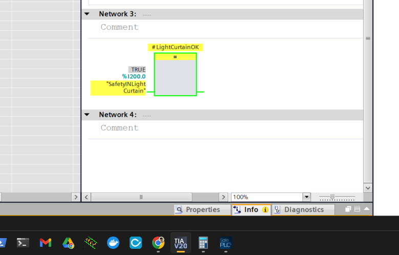
Network 3
Network 3 is a program that checks the Light Curtain status received via Profisafe.
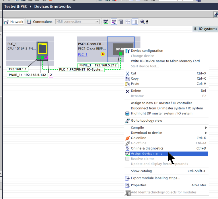
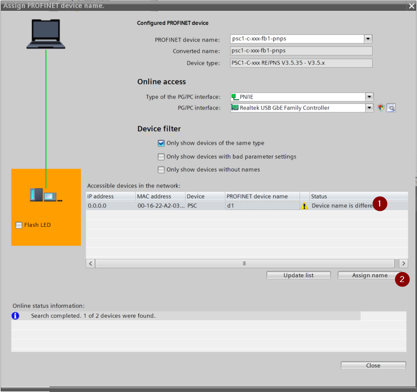
Assign Device Name
To assign a device name to the PSC-C-100-FB1, right-click and select “Assign device name”.
The “Assign PROFINET Device name” operation screen appears.
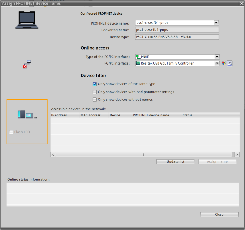
Click Update List.
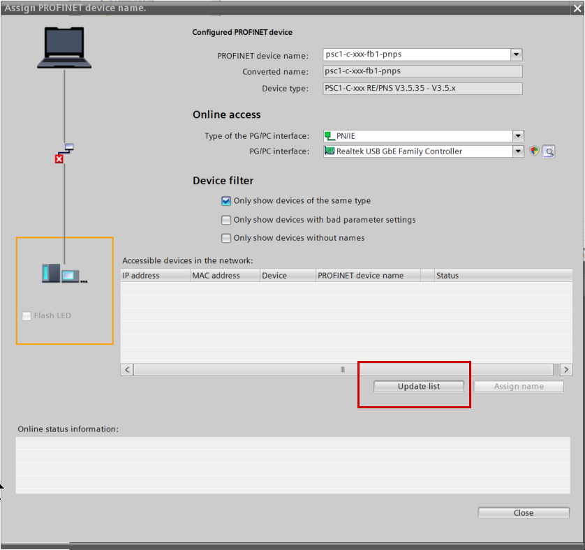
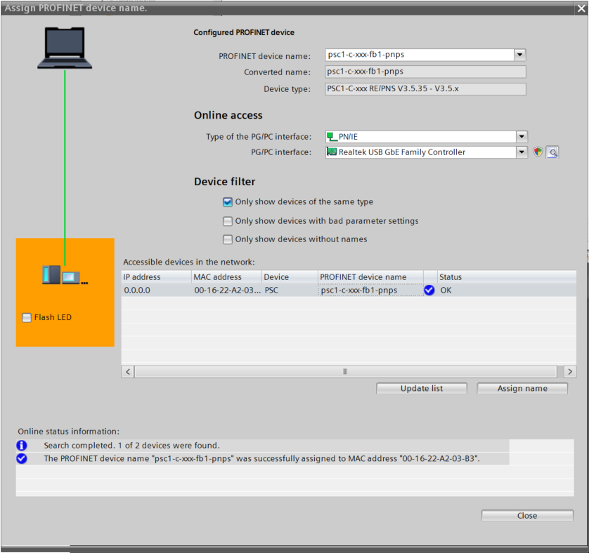
The PSC-C-100-FB1 was found; assign the Profinet device name with Assign name.
Done!
Download
Download the Hardware Configuration and the program to the CPU.
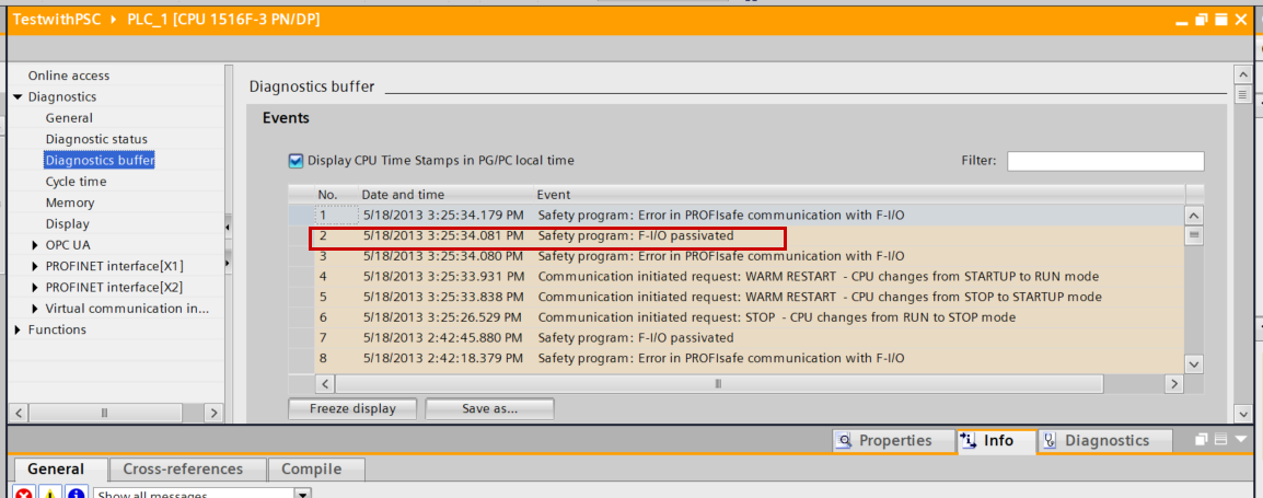
Result
Initially, an “F-IO Passivated” alarm occurs on the Profinet network.
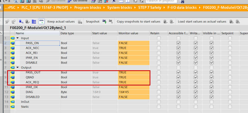
Click on the SafetyDB under System Blocks>STEP7 Safety>F-I/O data blocks>F00200_Fxxx.
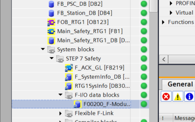
You can confirm that QBAD and ACK_REQ are TRUE.
- QBAD = Corresponding Profisafe device is in Passive state
- ACK_REQ = ACK operation required
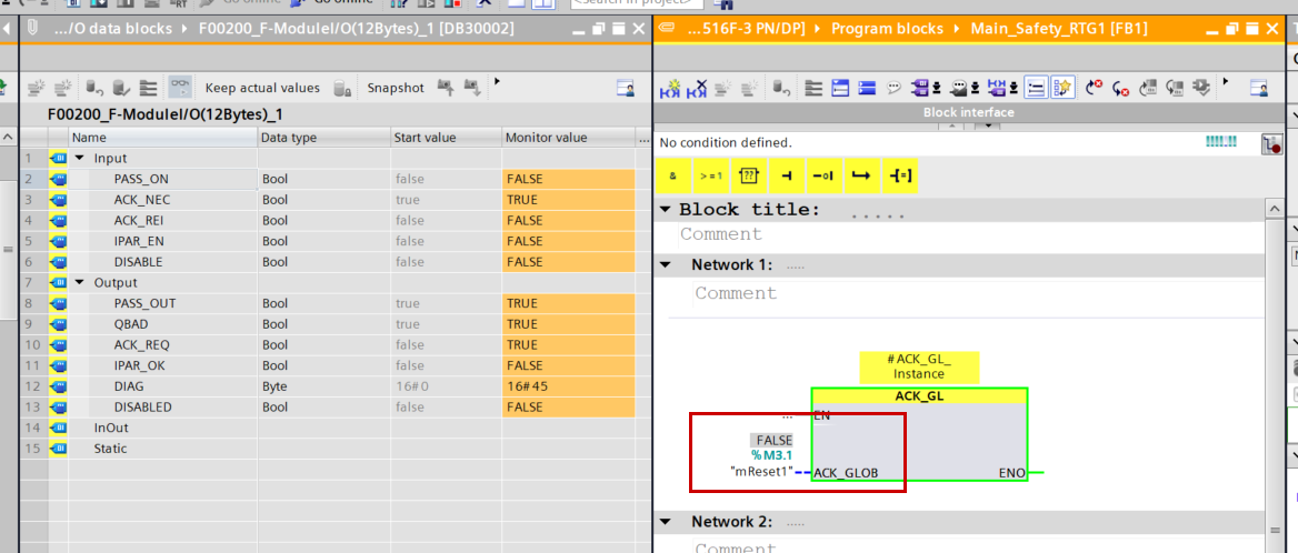
Therefore, set ACK_GLOB of the ACK_GL called in the safety FB to True.
Done! QBAD and ACK_REQ have also become FALSE.
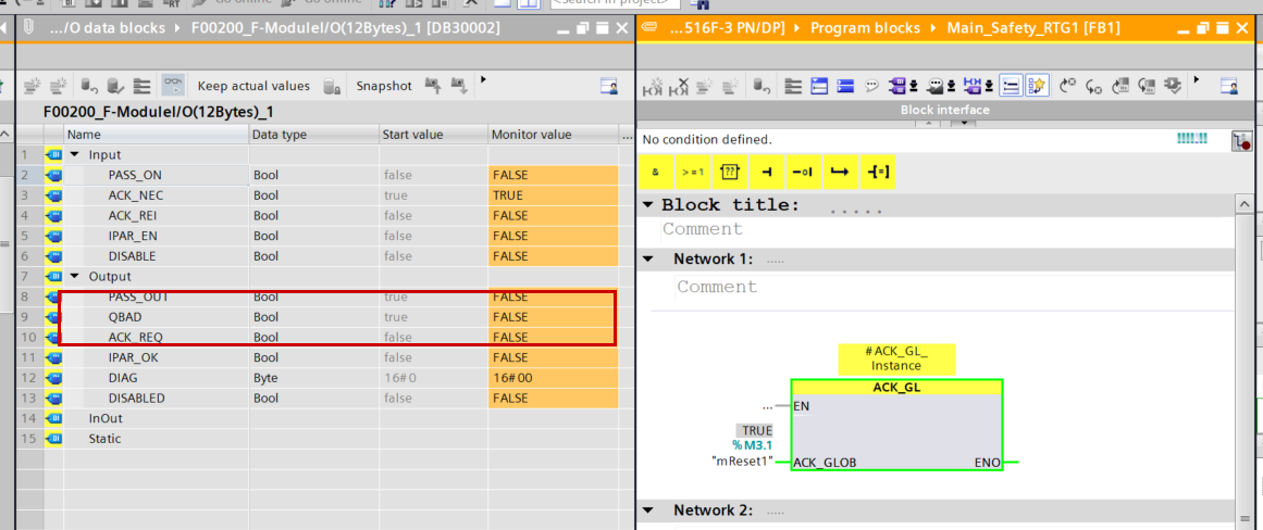
Profisafe data can now also be sent and received.
Confirmed that there are no communication errors on TIA as well.
The status of the safety devices connected to the PSC-C-100-FB1 could also be confirmed.
Send the reset permission signal from Siemens via Profinet.
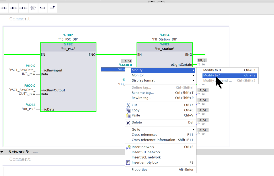
After pressing the reset button on the PSC-C-100-FB1 side, the Enable signal was also received!
The status of the signals can also be confirmed from the SafePLC2 tool.
You can check the operation in this video.
Download
You can download the TIA V20 program created in this article from this link.
https://github.com/soup01Threes/Siemens/blob/main/TestwithPSC.zap20