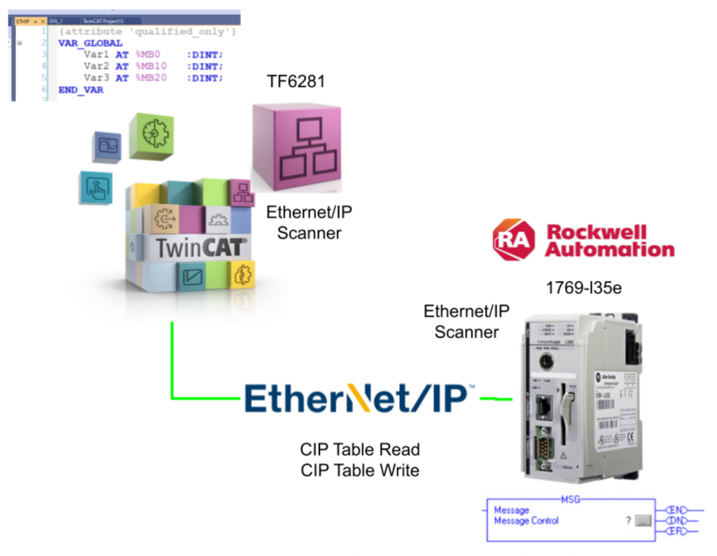
This article describes from scratch the construction of an asynchronous communication method between a Beckhoff TwinCAT3 TF6281 Ethernet/IP Scanner and a Rockwell PLC Ethernet/IP Scanner.
The Rockwell side uses the old PLC, but the same philosophy applies to the new device.
This time, the Rockwell side takes the initiative in executing functions and communicating asynchronously.
Let’s enjoy FA!
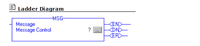
MSG Instruction?
The MSG instruction asynchronously reads and writes a block of data to another module on the network. In the ladder diagram, rung-condition-in is toggled from clear to set each time the instruction is executed.
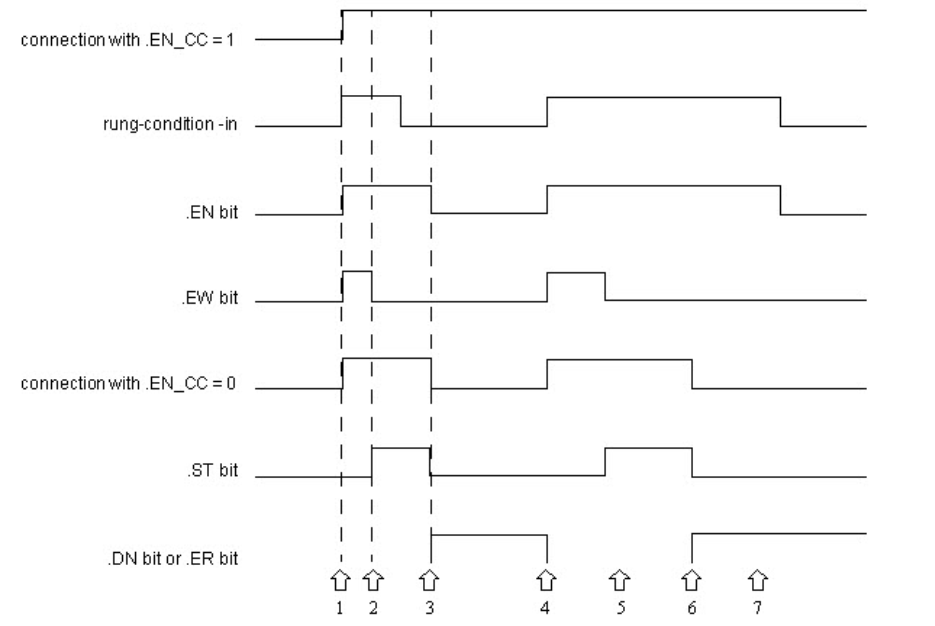
Time chart
Here is a time chart of the MSG function.
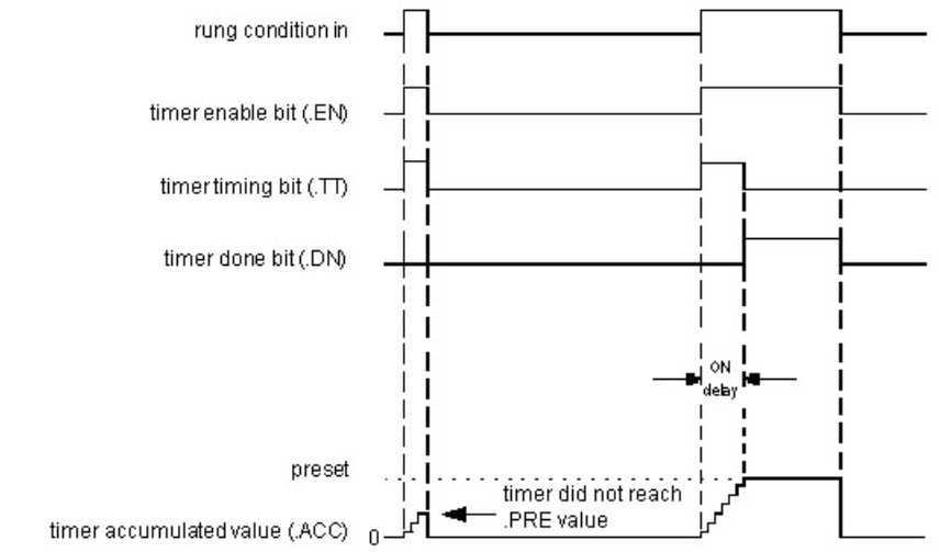
Timer On Delay (TON)?
The TON instruction is a non-retentive timer, which accumulates time when the instruction is valid (rung-condition-in is true). The timer operates by subtracting the last scanned time from the current time:
ACC = ACC + (current_time – last_time_scanned)

Time Chart
Here is a TON of time charts.
Implementation1-CIP Read Table
Beckhoff Side
Like Consumed and Produced tags, this feature is used for communication between two EtherNet/IP controllers, but differs in that it is acyclic communication. This allows data that does not need to be sent cyclically, such as parameters, recipes, and other data, to be exchanged between the two controllers.
Data can be structures, arrays, or a combination of both; TwinCAT can read data from and write to controllers, and it is possible to read and write data from and to TwinCAT using a remote control.
Notes:
- The data sent and received by this service must be known to the TwinCAT system.
- This data must be stored as global variables in the ETHIP folder and flags area.
- The library Tc2_EthernetIP must also be included and contains function blocks for reading and writing DataTable.
- The data types must match in both PLCs.
Configure Etherent/IP Network
Establish an Ethernet/IP network on the TwinCAT3 side.
Add Ethernet/IP Scanner
To add an Ethernet/IP Scanner, go to I/O>Devices>Add New Item.
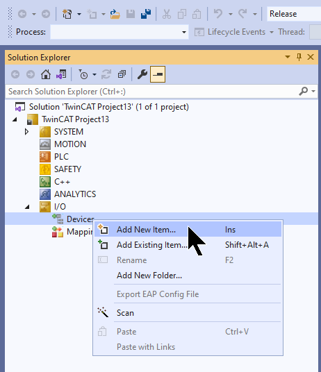
Select Ethernet/IP>Ethernet/IP Scanner>OK.
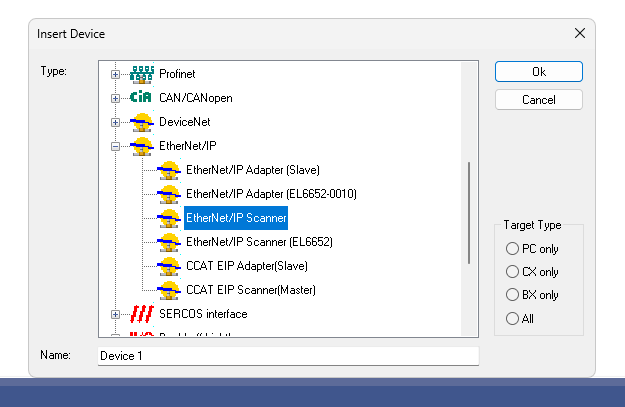
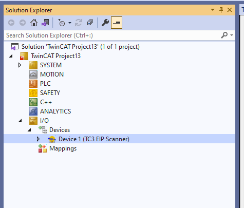
Done!Ethernet/IP Scanner has been added.
Configure Ethernet Adapter
Open the Adapter tab, click on the Serach button and search for an Ethernet Adapter that can be used with the PC currently running the TwinCAT Runtime.
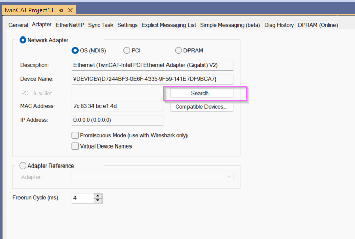
Set the appropriate Interface and proceed with OK.

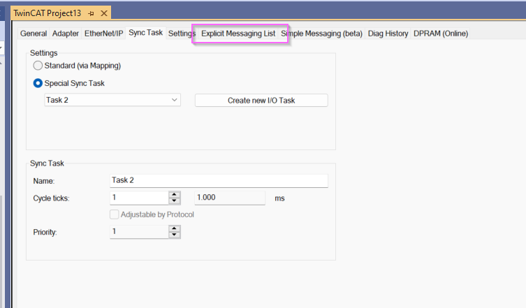
Configure Task
Next, to set up the Ethernet/IP Sync Task, click on Sync Task Tab > Special Sync Task > Create New IO Task.
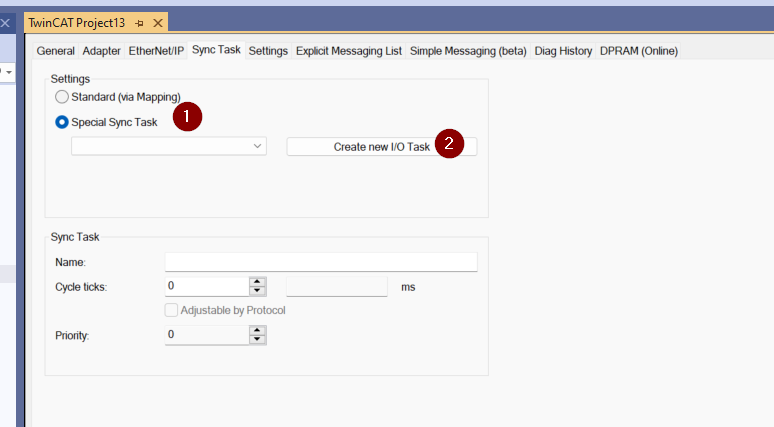
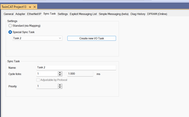
Enter a task name.
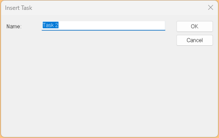
Done!
Configure IP Address
Set up TwinCAT’s Ethenret/IP Scanner IP address; Setup Settings>IP Address and Network Mask according to your application.
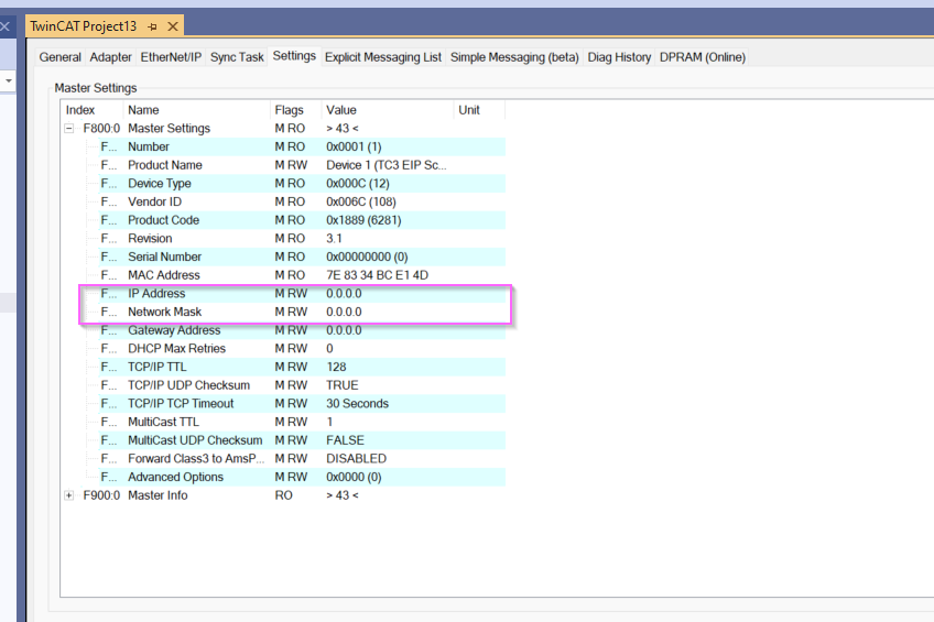
Done!

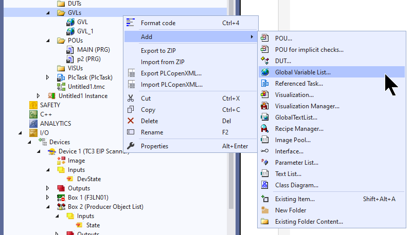
Add GVL
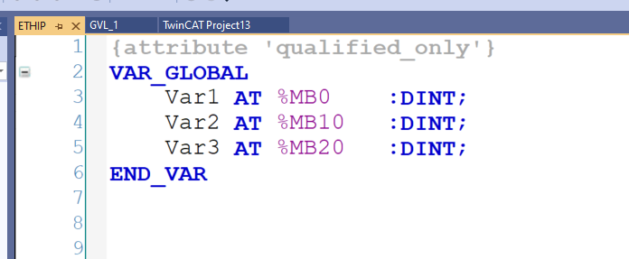
Add a Global Variables List and be sure to set the GVL name to ETHIP.
All variables have fixed addresses and must be defined in the flags area (%MBx, x addresses).
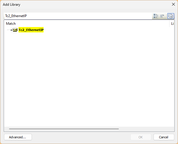
Add Library
References>Add Library to add a library for CIP Table communication.
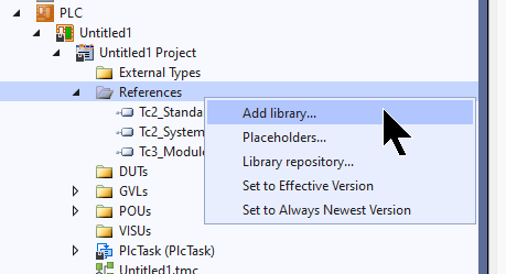
Add Tc2_EthernetIP.
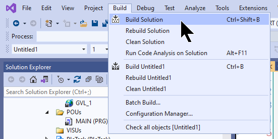
Build
Compile the project under Build>Build Solution.
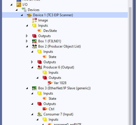
Configure CIP Table
Next, click on TC3 EIP Scanner to check the CIP Table in Ethenret/IP Scanner.
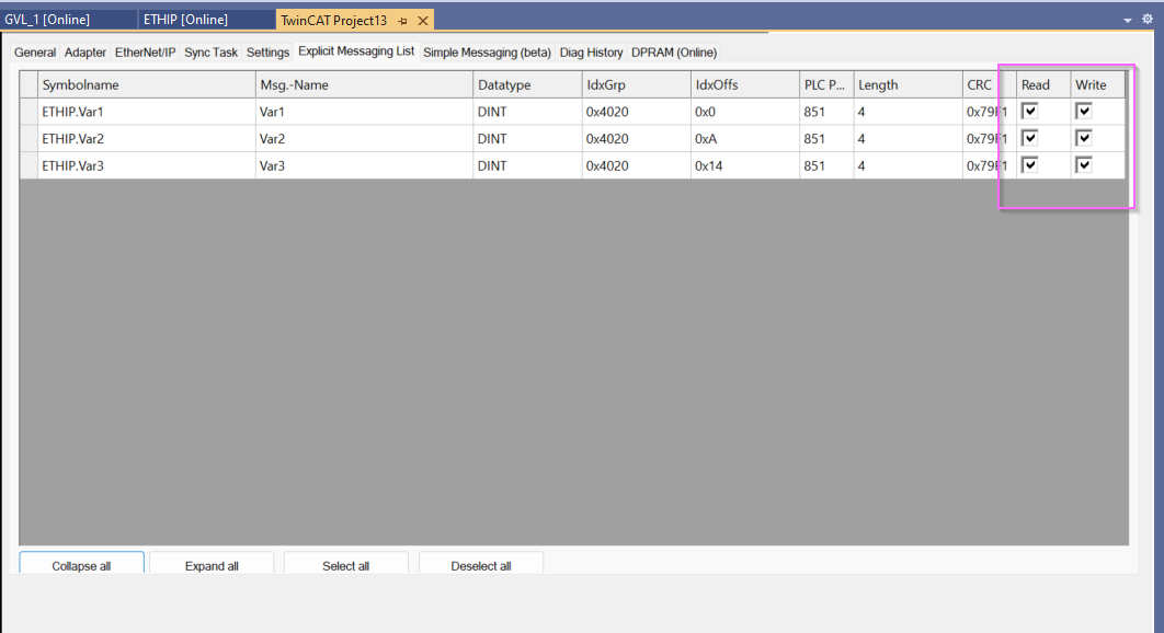
Click on Explicit Message List.
The variables just defined in ETHIP’s GVL are now displayed.
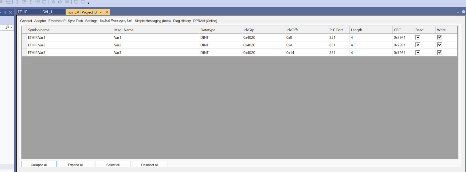
Be sure to set the Read/Write Checkbox to match the application.
Activate Configuration
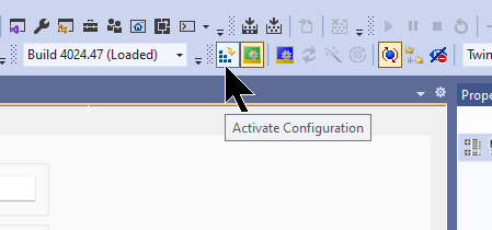
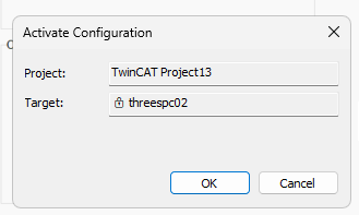
Click the Activate Configuration to download the Hardware Configuration to TwinCAT Runtime.
OK to proceed.
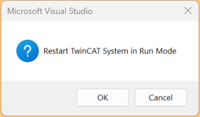
Switch TwinCAT Runtime to Run Mode.
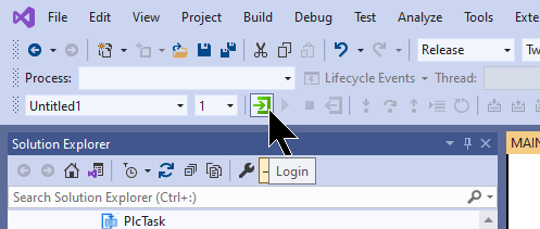
Login
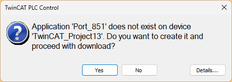
Download the program in Login.
Proceed with Yes.
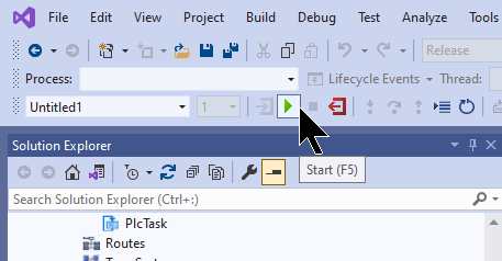
Start
Finally, start TwinCAT Runtime with the Start button.
Rockwell Side
Once the TwinCAT side has been built, the next step is to set up the Rockwell PLC.
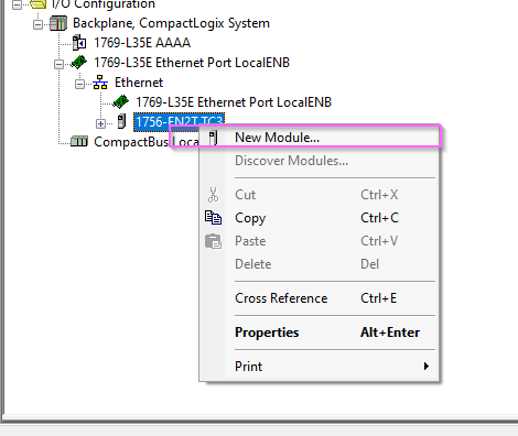
Add New Module
Add a temporary Rockwell Controller to create a TwinCAT3 connection in Hardware Configuration: LocalENB>Right click>New Module.

Add a Rockwell CPU. The model can be anything, so we will install a 1756-EN2T for this article.
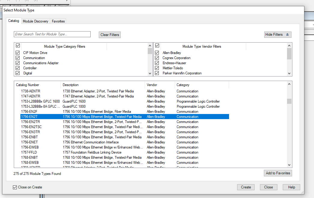
Done!

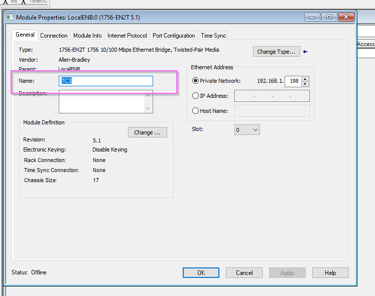
CPU Name
Set the CPU name to TC3 (TwinCAT3) so that the CPU you just added can be easily recognized.
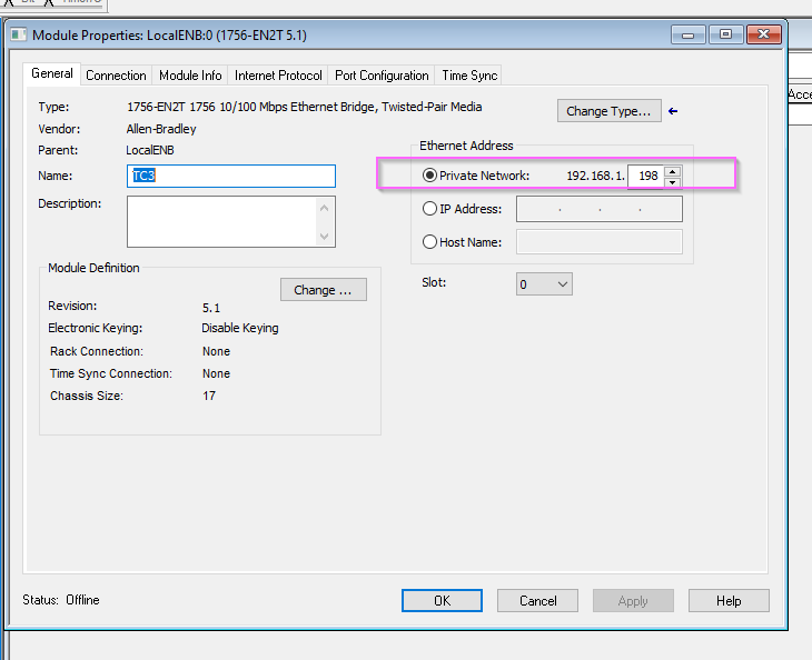
IP Address
Set the IP address to match the TwinCAT3 side.
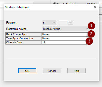
Module Definition
Next, click on Change to configure the Module.
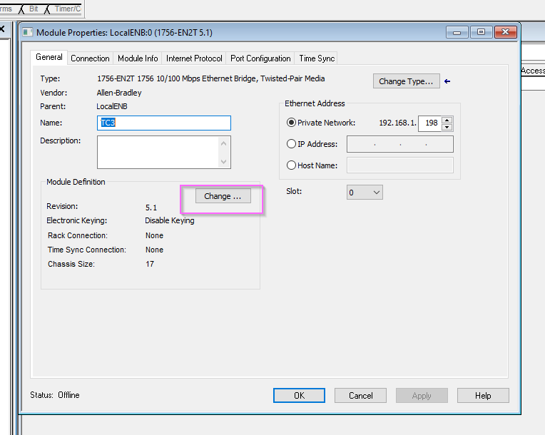
Since this article will only present the TwinCAT Ethernet/IP Scanner as a “Rockell” PLC, let’s disable Electronic Keying and set Rack Connection and Time Sysnc Connection to None.
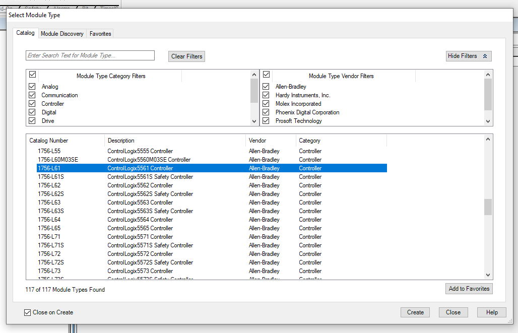
Add New Local PLC
Add a new module by right-clicking “Rockwell PLC” you just added and selecting “New Module.
For this article, we will set it to “1756-L61”.
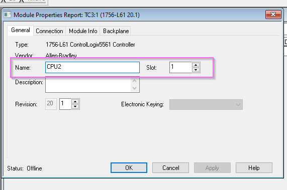
CPU Name/Slot
Set Module name and Slot to 1.
Add Power Tags
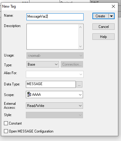
Define a new tag at Controller>Controller Tag>New tag.
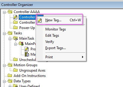
The Tag definition screen appears.
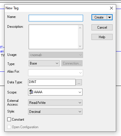
Define the variable name in Name and specify “MESSAGE” for Data Type.
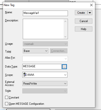
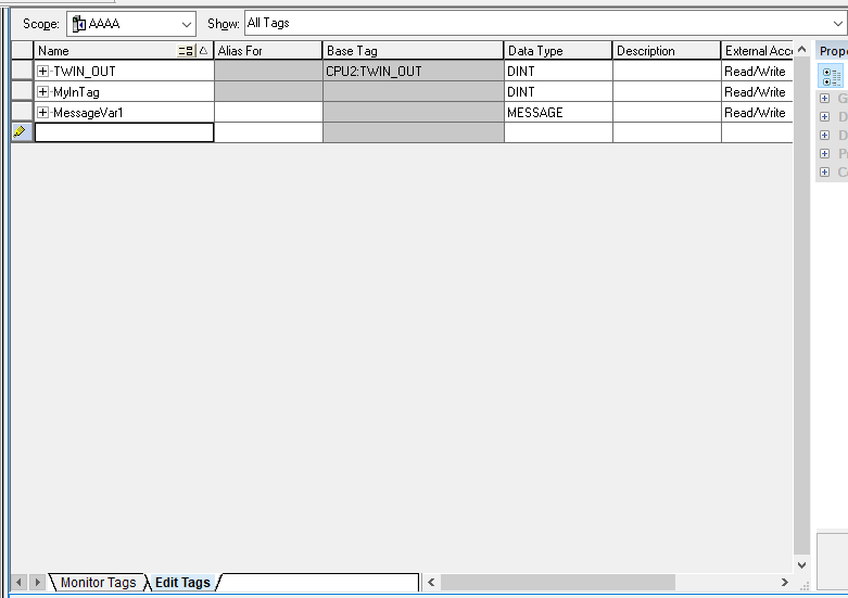
The MESSAGE variable is now defined.
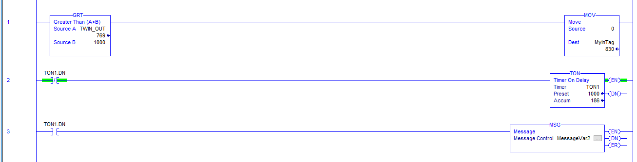
ADD MSG
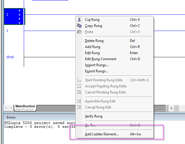
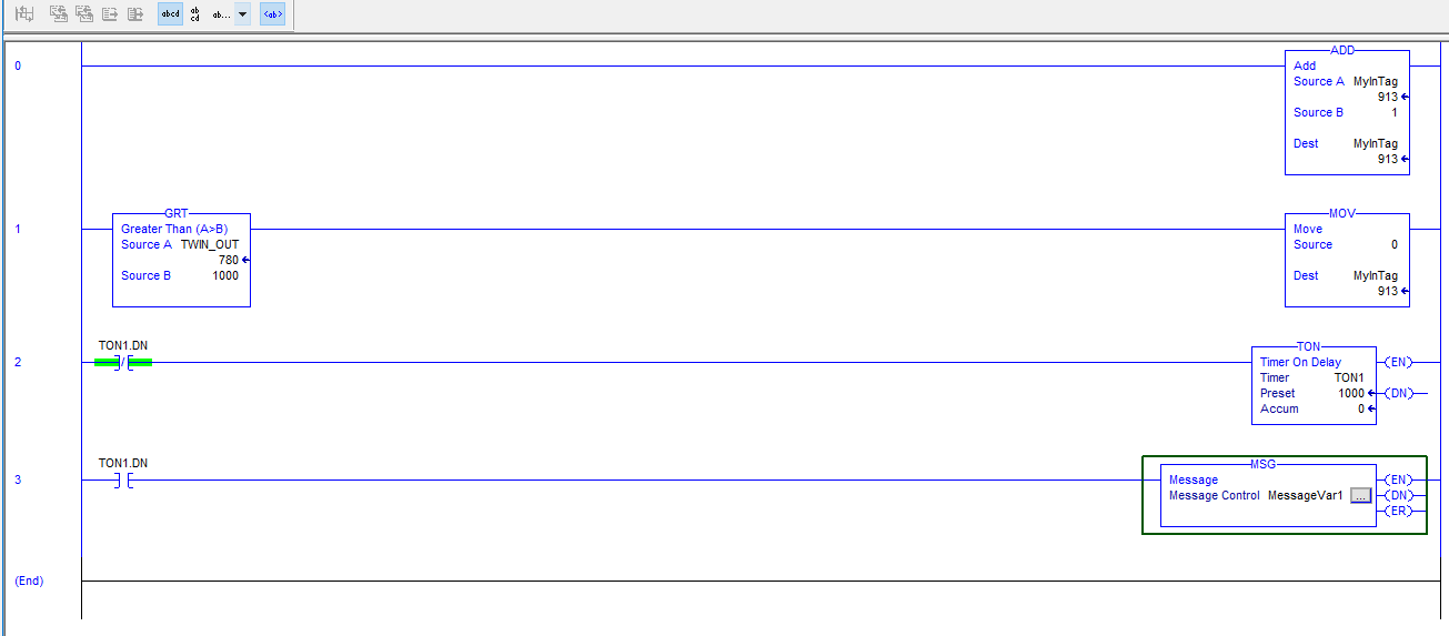
Right click on an empty rung on the ladder>Add Ladder Element to add a ladder component.
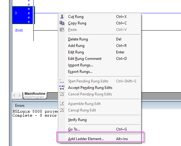
Choose Input/Output>MSG.
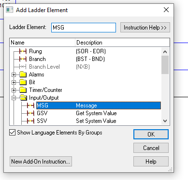
Done!MSG functions have been added.
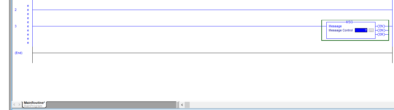
Configure MSG
Enter the MSG variable to be used in the MSG function.
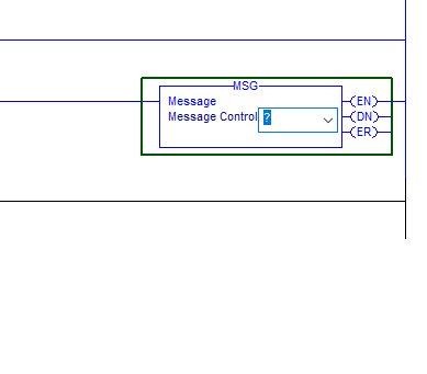
Use the MSG variable defined earlier.
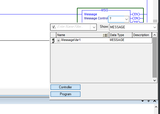
Next, to set up the MSG function, click on the … button in the MSG function.
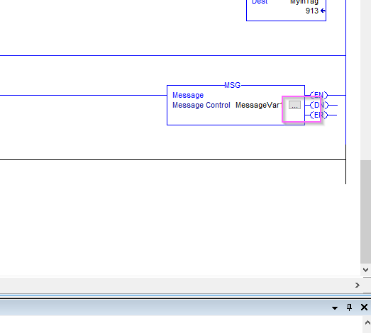
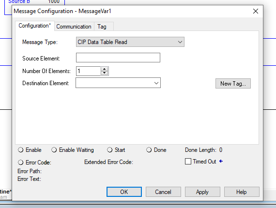
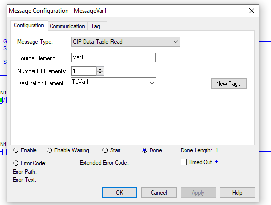
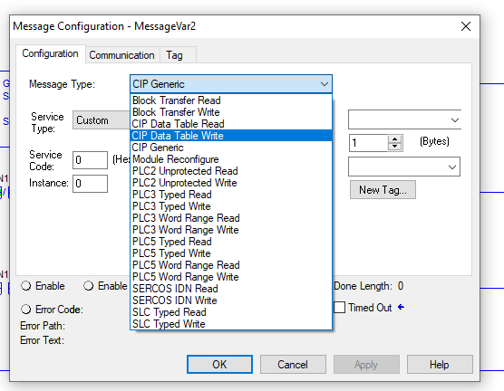
This is the MSG function setting screen.
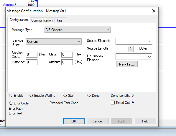
Message Type
Set Message Type to CP Data Table Read. This allows you to read variables in TwinCAT’s ENTIP.
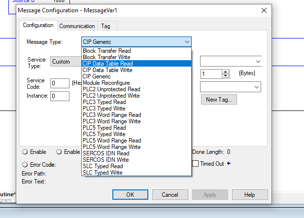
This is OK.
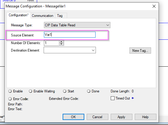
Source Element
The Soruce Element must match the variable name in the ETHIP on the TwinCAT side.
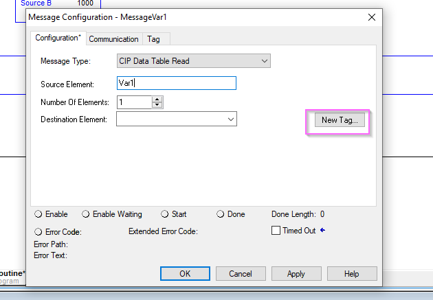
Destination Element
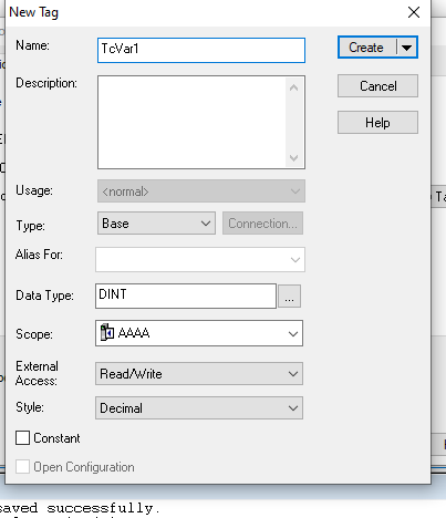
Click New Tag and define a Tag to store the data taken via the CIP Table Read service.
Here is the Tag setup screen.
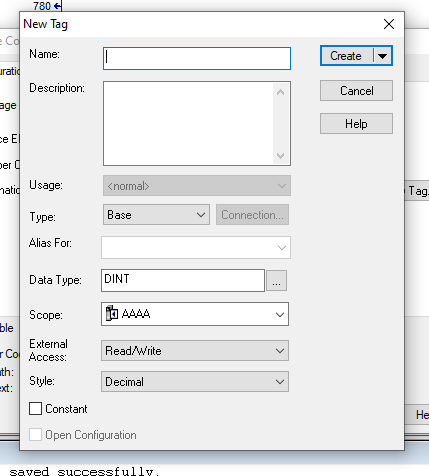
Set the tag name and data type.
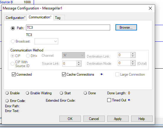
Communication
Next, open the Communication Tab for communication settings.
Check the Connected and Cache Connections checkboxes and click the Browse button to set the connection destination.

Select the TwinCAT PLC that you just added, which is disguised as a Rockwell PLC.
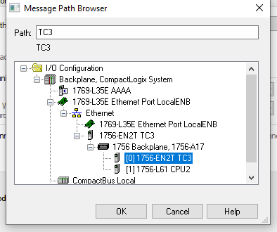
Connection Path is set Ok.
Add a Reflesh Timer
To add a timer, insert a new ladder component in the empty rung of the ladder by right-clicking>Add Ladder Element.
Add a delayed ON timer with Timer/Counter>TON.
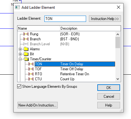
Done!
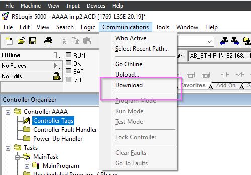
Download
Finally, to download the program on the Rockwell side, go to Communication>Download.
Proceed with Download.
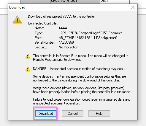
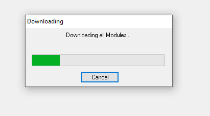
Please wait a moment…
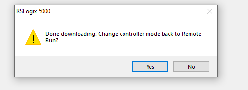
Proceed with Yes.
Result
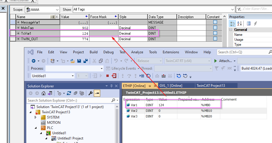
The Done light turns blue and the Error Code is empty, so the MSG function has completed execution without error.
The current value of ETHIP.Var1 of TwinCAT is reflected on the Rockwell side.
Implementation2-CIP Write Table
Next, let’s try writing TwinCAT variables from the Rockwell PLC side.
Rockwell Side
Add Power Tags
Add a MESSAGE variable using the same operation as before.
ADD MSG
Add and define MSG functions using the same operations as before.
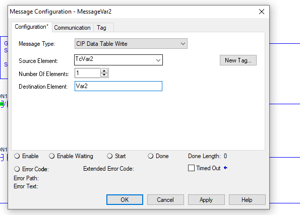
Message Type
Set the Message Type of the MSG function to CIP Data Table Write.
Done!
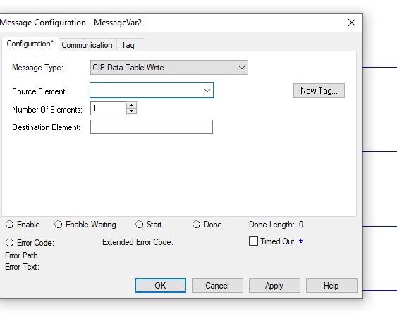
Source Element/Destination Element
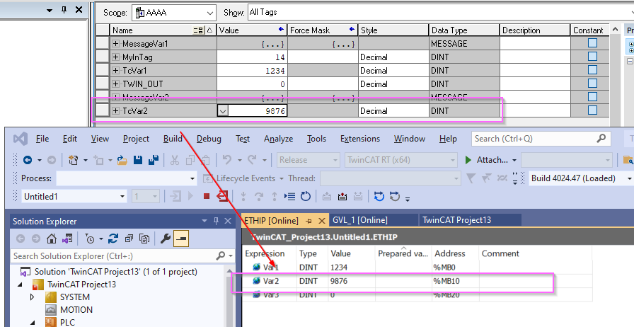
Souruce should be set to the Rockwell PLC variable and Destination should be set to match ETHIP.Var2 on the TwinCAT side.
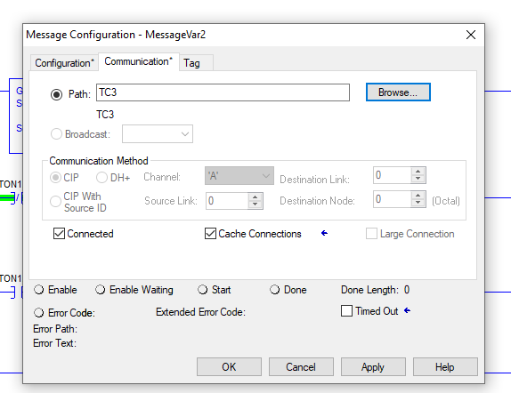
Communication
Open Communcation Tab and make Path to TwinCAT PLC disguised as Rockwell PLC.
Download
Finally, to download the program on the Rockwell side, go to Communication>Download.
Proceed with Download.
Please wait a moment…
Proceed with Yes.
Result
The Done light turns blue and the Error Code is empty, so the MSG function has completed execution without error.

The current value of ETHIP.Var2 in TwinCAT has been changed on the Rockwell side.