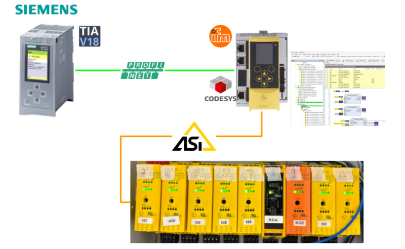
This article describes the steps from the first, from setting up an AS-i network using IFM’s AC402s to Profinet communication with a Siemens S71500.
Come on, let’s enjoy FA!
Foreword
Thank you from the bottom of my heart for visiting my technical blog and YouTube channel.
We are currently running the “Takahashi Chris” radio show with Full-san (full@桜 八重 (@fulhause) / X) which I deliver every Wednesday night.
Currently, our activities continue almost free of charge, and your warm support is very important for us to provide more content.If you are able, we would be very happy if you could support us by clicking on the links below.
Membership of Takahashi Chris
You can sign up for a membership to the radio we are doing with MR.Full (full@桜 八重 (@fulhause) / X from here.
https://note.com/fulhause/membership/join
AMAZON Gift List
This will be of great use to me in creating content for my blog and improving my facilities.
https://www.amazon.co.jp/hz/wishlist/ls/H7W3RRD7C5QG?ref_=wl_share
Patreon
Here is a small Patreon of support for the creation of content and equipment for my blog.
https://www.patreon.com/user?u=84249391
Your support will help us to enhance our activities.
Thank you in advance for your support.
Email Address(*=@)
X
AC402S?
The IFM AC402S has the following features:
- Integrated fieldbus interface and fail-safe PLC
- Reliable and fast data exchange with sensor actuator level
- Colour display showing status of all AS-i slaves
- User-friendly and easy configuration, set-up and diagnosis
- Quick set-up menu for intuitive operation

Layout
This is the Layout of the AC402S.

Ethernet
Configuration interface 1 (X3) is located behind the front flap of the device and configuration interface 2 (X8) is located below the PROFINET interface (X6/X7).
Users can access the following functions from both interfaces
- Web interface for configuration and diagnostics
- Programming of equipment internal standard PLCs and fail-safe PLCs with CODESYS
- Operation as additional fieldbus interface
Local input/output interface
The local input/output interface (X4) is located behind the front flap of the device, allowing safe and non-safe or peripheral devices without an AS-i interface to be connected to the local inputs and outputs.


Local Inputs
The local I/O interface provides eight input channels for connecting devices (e.g. sensors, switches, light curtains). Each input channel can be used as a safety input or a standard input.Their configuration is possible from CODESYS.
Local Outputs
The local I/O interface provides four output channels for connecting devices (actuators, relays, etc.). Each output channel can be used as a safety output or a standard output.Their configuration is possible from CODESYS.
Architecture
This is AC402s Architecture.

Main module
The main module is the central component of the AC402S, containing the recovery system and device firmware, and controls communication between individual system components via the backplane.

Display
The display is the graphical user interface of the AC402S, through which the user can configure and diagnose the device. The display exchanges result data with the main module.

COM module
The COM module provides the PROFINET functionality of the AC402S. It comprises the PROFINET connection and the required firmware. The COM module receives fieldbus data from the main module via the interface and transfers it to the fieldbus. At the same time, it receives data from the fieldbus and transfers it to the main module.

AS-i module
The AS-i module provides the AS-i functions of the AC402S, such as receiving, evaluating and transmitting AS-i telegrams, without any logical pre-processing.
The AC402S contains two AS-i masters and controls two AS-i telegrammes.
The following number of AS-i slaves can be connected to each AS-i master:
- Up to 62 non-safe AS-i slaves or
- Up to 31 Safe AS-i input slaves or
- Up to 15 AS-i control slaves controlling safe AS-i output slaves
The AS-i module exchanges data between the safety module and the safety AS-i slave via the backplane.All AS-i data is provided to the main module for display on the display.

Safety module
The safety module contains the safety-related hardware of the AC402S. The architecture of the safety module has the following structural features
- 1oo2 hardware architecture (1 out of 2 architecture)
- 2-channel architecture with separate diagnostics for both channels
- 2-channel safe input selectable
- 1-channel and 2-channel safe output selectable
- Integrated testing in the safety processing unit (safety CPU1/2)
- Hardware fault tolerance (HFT) = 1
The safety module consists of the following components:
- Safety CPU PCB with 2 processors for control technology signal processing (Safety CPU 1/2)
- Safety I/O PCB with independent power supply for local I/O interfaces
Both PCBs are galvanically isolated from each other and they are supplied from separate voltage sources.Both safety CPUs have separate watchdog and reset circuits, which are interconnected by mutual communication.Both PCBs are also interconnected via a serial interface for bi-directional data exchange. The safety module has interfaces to the main module and the AS-i module.

Operating states of AC402S
The operating conditions of the AC402S are as follows:
- INIT
- NORMAL OPERATION
- SYSTEM STOP

INIT
After starting, the device automatically enters the INIT state. In the INIT state, the device undergoes various hardware tests and integration tests (PBIT = Power-up Built-In Test).
- If the PBIT test is successful, the device enters the NORMAL OPERATION (2) state.
- If the PBIT test is not passed, the device enters the SYSTEM STOP (3) state.

NORMAL OPERATION
In NORMAL OPERATION, standard PLC and fail-safe PLC devices provide the working environment. The states and modes of operation of the PLC application are valid at the same time, irrespective of the processing of the PLC application.In addition, the device is continuously subjected to various hardware tests (CBIT = continuous built-in test).If this CBIT test is not passed, the device enters the SYSTEM STOP state ( 4 ).

SYSTEM STOP
In the SYSTEM STOP state, the equipment is in a safe state. To remove the SYSTEM STOP state, the operator must perform a power-on reset.
The device changes to the INIT state (5 ).

AS-i
AS-Interface (Actuator-Sensor-Interface) is a globally standardized fieldbus system for connecting sensors and actuators to a higher-level controller via a common data transmission medium.
AS-Interface is used at field level and typically serves to transfer process data to a higher control level.For example, field devices can be integrated into existing networks directly via so-called ASi masters or via gateways.Specific information and process data are transmitted between field devices and controllers using a two-wire yellow AS-Interface profile cable.This special AS-Interface cable is used for both data transmission and power supply to the field devices.

Simple configuration
Master-slave communication model
At the field device level, the AS interface is managed by the master-slave principle.
- Communication between the ASi master and the slaves (field devices) takes place as cyclic requests.
- The ASi master manages the data traffic and connects the participants to the higher-level controller.
- The master monitors and controls the entire data exchange in the network.
- The ASi master sends information to the slaves, which in turn evaluate the information (and filter the information for the slaves) and send a response back to the master.
- Slaves can be simple individual field devices or compact field modules.

Integration options of AS-Interface in automation systems
As a standard, AS-Interface is implemented as a sub-fieldbus system for established high-performance fieldbus systems and industrial Ethernet.This extends down to the lowest field level.

PLC
A programmable logic controller (PLC) is a specialised computer used primarily in industry for control and regulation purposes.

Gateway
Gateways are used to connect different types of networks and communication services.

Actuator-Sensor
Actuator-sensor interfaces are intelligent wiring systems that replace individual wiring to connect actuators and sensors to programmable logic controllers and other control devices.

topology
AS-Interface offers a flexible choice of network topologies. As a result, linear structures are just as suitable as star and tree structures. The ASi protocol enables modular expansion of industrial communication networks and individual adaptation to the topology of existing systems. At the same time, cabling in the network can be reduced. This level of flexibility leads to a significant reduction of cabling man-hours in the network.

AS-Interface flat cable
The yellow AS-Interface flat cable is characterised by the fact that data transmission and power supply to field devices take place over the same 2-wire profile cable.
For additional supply of specific 24 VDC field devices or modules, black profile cables are used as required; the maximum cable length per segment is 100 m, but can be extended e.g. by using repeaters.
Field devices can be connected directly to the AS interface cable via a push-in connector. Piercing technology is used to connect the devices. During installation, two piercing needles attached to the cable penetrate the flat cable insulation and establish a secure connection to the network.
AS-Interface cabling technology is regarded as a simple, efficient and economical network. The use of AS-Interface flat cables for simultaneous power supply and data transmission prevents wiring errors.
In addition, it reduces cabling and associated installation costs.

AS-I Safety?
The Actuator-Sensor Interface (AS-I) is a master-slave bus operating at the lowest level of the fieldbus hierarchy. It replaces the parallel wiring of sensors and actuators with a single two-wire cable carrying both data and power. Devices (also called “nodes”) can be added anywhere on the cable and in any topology, such as line, ring or star.
In some cases, these sub-devices are an important part of the safety function in the machine.Therefore, their communication with the master controller must also be “safe”.
AS-Interface addresses the need for safe communication between safety components and higher-level controllers with the development of AS-I Safety at Work.The solution enables safety devices to be connected to the same AS-I cables and fieldbuses as standard (non-safety) devices.
Safety devices with an AS-I Safety at Work interface can be connected directly to the AS-I cable. Devices without an AS-I Safety at Work interface can be connected via special interfaces called ‘coupling modules’ or ‘adaptive devices’.
The solution not only utilises the simplicity of AS-I implementation, but also eliminates the cost and complexity of redundant infrastructure. In addition, the safety concept can be easily modified as needs change. Safety devices can be added, moved or replaced as required, with no implementation restrictions and no new wiring required.

AS-Interface Safety at Work enables system wiring up to category 4 performance level e according to EN ISO 13849 or SIL 3 according to IEC 61508. The system designer determines the appropriate combination of safety components and sets up the safety monitor configuration according to the selected control category. By selecting the appropriate components, Performance Level e, Category 4 can be achieved. Testing of all safety functions is mandatory.
Safety monitors function in the same way as safety relays. Safety monitors or safety controllers have output circuits including two redundant release circuits and are generally available up to performance level e in control category 4.The functionality of the safety monitor goes far beyond a single safety relay due to the additional integrated safety logic module. Depending on the application, a single safety monitor can replace several conventional safety relays, significantly reducing wiring and saving space in the control cabinet.
To achieve the desired safety category, designers need to ensure that safety components and associated safety functions are coordinated and documented accordingly during the configuration of the safety monitor. The specific functions of the safety monitor perfectly support the work of the functional safety engineer.

The key to AS-Interface Safety at Work is the Safety Monitor, which monitors up to 31 safety-related devices on the AS-I bus, such as e-stops, light curtains and door latches. Each safety device has a manufacturer-defined code table (list of 4-bit binary numbers), which is stored by the Safety Monitor. When the master controller polls the safety device, the safety device transmits its status with a 4-bit code from the code table.
The safety monitor ‘listens’ to this communication and compares the code sent by the safety device with the code stored for that device. If the code is not listed in the code table for that device, or if there is a problem with the network communication (e.g. interrupted, missing or delayed response from the device), the safety monitor will switch off the relevant safety output with a reaction time of up to 40 ms.

Benefits?
Using the AS-I interface offers the following advantages
Simplicity and efficiency
- Simple and quick installation of field devices
- Easy connection to the controller
- Cost savings by reducing the number of cables in the network
- Space-saving wiring
- Easy maintenance
- Simple network configuration
flexibility
- Free topology: various network topologies are possible
(linear, star and tree structures)
- Flexible integration of field units: direct or decentralised
High reliability
- The entire system is protected by intelligent protocols, making it less susceptible to interference.
- The well-protected input/output modules eliminate the need for control cabinets in the plant.
Function Block
Here are the FBs used in this article.
CtrlASi_InSlave
FB for controlling the logical devices of the ASi_Master. The programmer can perform the following actions via CtrlASi_InSlave:
- Unlocks the logical device and resets it from the locked error state S_ERROR to the initialised state.
- State S_INIT (RESET)
FBs provide the following condition and diagnostic information as non-safety data:
- Logical value of the two safe code half sequences of the AS-i input slaves (Chan_A and Chan_B)
- State of the FB process (ready)
- Error status of function block (Error)
- Diagnostic information of logical devices (DiagCode)

VAR_INPUT
| parameter | data type | Description |
| Enable | BOOL | TRUE=Enable FB |
| ASi_SlaveAdr | INT | Addresses of secure AS-i slaves1=Slave address 1… |
| ASi_Master | INT | AS-i master number to which the secure AS-i slave is connected.1=AS-i Master 12=AS-i Master 2 |
| Reset | BOOL | 1 = Reset, control signal to reset the device from the locked error state (S_ERROR) to the initialisation state (S_INIT). |
VAR_OUTPUT
| parameter | data type | Description |
| Chan_A | BOOL | Chan_A BOOL Logical state of safety signal channel A (first court half sequence) |
| Chan_B | BOOL | Chan_B BOOL Logical state of safety signal channel B (second court half sequence) |
| Ready | BOOL | FB processing status, TRUE=FB is processed without error. |
| Error | BOOL | Error indication, 1 = Error present, logical device locked error status S_ERROR. |
| DiagCode | WORD | Diagnostic codes for the internal state of the controlled logical device. |
CtrlASi_OutSlave
FB for controlling the logical devices of the ASi_Master.
Programmers can use CtrlASi_OutSlave to perform the following actions:
- Signal to unlock the safe AS-i slave (auxiliary signal HSI_1)
- Transmission of an auto-start signal (auxiliary signal HSI_2)
FBs provide the following condition and diagnostic information as non-safety data:
- State of FB processing (ready)
- Error status of function block (Error)
- Diagnostic information of logical devices (DiagCode)

VAR_INPUT
| parameter | data type | Description |
| Enable | BOOL | TRUE=Enable FB |
| ASi_SlaveAdr | INT | Addresses of secure AS-i slaves1=Slave address 1… |
| ASi_Master | INT | AS-i master number to which the secure AS-i slave is connected.1=AS-i Master 12=AS-i Master 2 |
| HSI_1 | BOOL | Auxiliary signal 1 (HSI_1) Reset signal to get out of locked error state (S_Error) |
| HSI_2 | BOOL | Auxiliary signal 2 (HSI_2) Automatic reset of AS-i slaves after communication errors |
VAR_OUTPUT
| parameter | data type | Description |
| Ready | BOOL | FB processing status, TRUE=FB is processed without error. |
| Error | BOOL | Error indication, 1 = Error present, logical device locked error status S_ERROR. |
| DiagCode | WORD | Diagnostic codes for the internal state of the controlled logical device. |
CtrlASi_ResetAllSlaves
FB for controlling the logical devices of the ASi_Master.
Programmers can use CtrlASi_ResetAllSlaves to perform the following actions:
- Unlock all secure AS-i slave logical devices in the indicated network and reset them from the locked error state S_ERROR to the initialisation state S_INIT (RESET).
FBs provide the following condition and diagnostic information as non-safety data:
- State of FB processing (ready)
- Error status of function block (Error)

VAR_INPUT
| parameter | data type | Description |
| Enable | BOOL | TRUE=Enable FB |
| ASi_Master | INT | AS-i master number to which the secure AS-i slave is connected.1=AS-i Master 12=AS-i Master 2 |
| Reset | BOOL | 1 = Reset. |
VAR_OUTPUT
| parameter | data type | Description |
| Ready | BOOL | FB processing status, TRUE=FB is processed without error. |
| Error | BOOL | Error indication, 1 = Error present, logical device locked error status S_ERROR. |
State diagram (state machine)
The state diagram shows the logical signal evaluation of the logical device:

Implementation
Now we can actually build the project.
IFM Side
Start with the IFM AC402S first.

Plug ip the service Port
Connect the PC to service port X3 of the AC402S.

Configure Service IP Address
The next step is to set the IP address of the X3 using the screen and control buttons on the AC402S unit.

Use the right and left arrow buttons to get to the Interface item and select it with the down arrow button.

Next, select X3 and click the left button.

Finally, use the down arrow to find the IP address setting item and set the appropriate IP address.

Access As Browser
After setting the IP address of the X3Port on the AC402S main unit, you can access the CPU’s Web Server from the Browser.From now on, you can set and monitor parameters without having to look at the control buttons or Display.

Start to project the As-i Interface
The first step is to set up AS-i 1.

Use Project Mode: when the AC402S is in Project Mode, it will automatically connect any AS-I Slave other than address 0.

Check out Address
Now check the status of the Slave connected to AS-I 1.

Done!The AC402S was able to recognise some ASI Slaves.

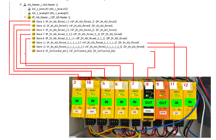
This is the address setting of the AS-I slave used on the actual device in this case.

AS030s
Setting up the AC030S is a bit tricky, so set the DIP switch on the unit from R to P (on the right).

Next, go to the AC030S Slave settings screen from the AC402S Web Server screen you have just entered.

Set the Slave address and also check the Profile value.

If you also want to change the Slave address, click Change AS-i Slave address.

Set up a free address in the network.

Finally, set the DIP switch to R (left side).

Codesys Project
System>PLC>Project Information to see which Codesys projects are currently running in AC402S.


Codesys status
The capacity of the Codesys project can also be checked for the same.


Project Information
You can check the CPU’s firmware and serial number under System>Information.


Time Setup
It is important to set the time on the CPU, so that you can see what is happening at any given time, even when there is a problem – you can change the time in System>Setup.


Slave Safety Status
Safety>AS-I 1で現在のAS-I Safetyネットワークの状態を確認できます。


Plug in Profinet Port
This article also uses Profinet, so connect the Port in the diagram below to the Profinet upper Controller.

Project all
Finally, once you have completed checking the status of all AS-i Slaves, use Project All>Start projection process to apply the current network settings as project data.

Codesys Side
The next step is to build the Codesys project in AC402S.

Download Packages
Download the Safety PLC Package from the IFM website.
https://www.ifm.com/de/en/product/AC402S#documents
There are also several Version versions available on HP, and you should download and install the appropriate Packages File for your AC402S Controller Firmware.

You can check the Run Time Version of Codesys from the AC402 Web Server.
Lauch Codesys
Start the SmartPLC SafetLine after the installation of the Codesys Package is complete.

Create New Project
The next step is to create a new project.This time, select Basic Project from Template and press OK to proceed.

Done!

Configure Safety As-i Slave
The next step is to build an AS-i safety Slave.In this article, only AS-i Master 1 will be used, so click Asi_Master_1>SF_ASi_Master_1>Right click>Add Device.

This is the additional screen for the AS-i Safety Slave.

In the diagram below, the upper frame is the Safety input and the lower frame is the Safety output relationship.

Now we want to add AC009S, so select SF_IN_AS_forced and add it under >Add Device.
Also, the items to be added vary from device to device and are not explained in detail here.

Done!When a Safety AS-i Slave is added, the same device is added to the Safety PLC side.

The next step is to set the address of the AS-i Safety Slave.

Open the Tab under Safe ASi IO Parameters and set the address of the relevant slave in the Value of Slave Address.

In this example, it is set to “3”.

If Slave Address is set to 3, the corresponding device name is also automatically changed and reflected on the Safety PLC project side.

Set up other Slaves in the same way, according to address and use.

This is the Hardware Configuration for Safety Slave.
In addition, the 9th AC2264 is not a Safety AS-i slave, so input/output data is reflected in ASi-binaryIO.
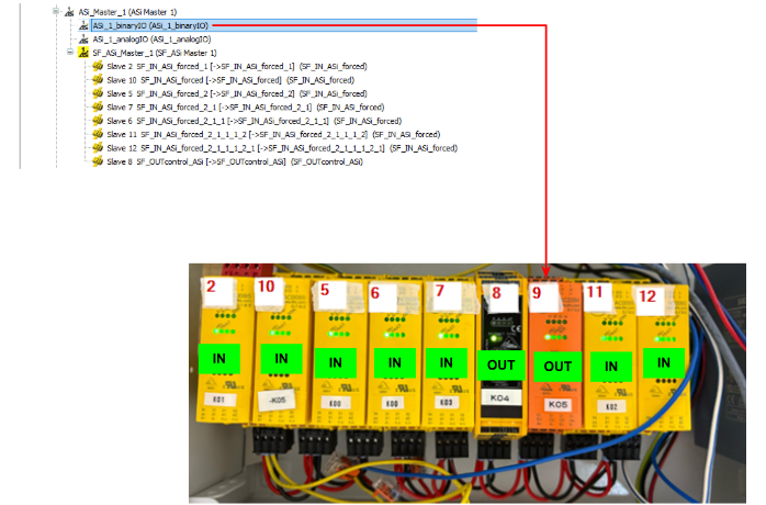
The Mapping of that ASi-binaryIO can be accessed in the form of an array.The arrays are divided into A/B and input/output, e.g. for the 9th AS-i Slave, the input/output is accessed from the Byte data with Index=9.

Safety Program
The next step is to create a safety program.

Configure Non Safety Exchange Data
Logic I/Os have an additional slot for data exchange between Safety PLC and Non-PLC on Default.

Click on the relevant Slot to go to the I/O Mapping screen, where you can map the variables of the safety PLC.The diagram below shows the data in Input, i.e. from the safety PLC to the safety PLC.

This is Output data, i.e. the output from the safety PLC to the non-safe PLC.

If you want to add data exchange between the safety PLC and the non-safety PLC, right-click on Logic I/Os>Add Object>Logical Device.

The Add Logical I/O screen appears and Scroll to the bottom.

We will use IFM’s Logical Exchange Object as we will be using IFM’s AC402s in this article (as IFM’s slots have a large capacity of 32 words).

Done!

The next step is to define some variables (safe PLC → safe PLC) according to the application.

This will pass the ChanA and ChanB status and reset status of each Slave to the non-safety PLC.

Safety Process IO Mapping
The next step is I/O Mapping, as you want to use each AS-I Safety Slave input/output for your safety programme.

Enter the name of the variable in the Safety BOOL.

Do the same for the safety outputs.


Safety Program
To create a safety program from now on, open SafetyPOU.

MAIN
This is the safety programme created in this article.

Network1-2
Network 1 passes the enabling signal of the safety FB as well as the signal to reset from the non-safety PLC to the safety programme.

Network3
Network 3 is the programme for resetting all AS-I slaves.

Network4-5
Networks 4-5 retrieve the input status and diagnostic codes of the safety Slave of ID 2 of ASi-1.The same operation applies to the other Slaves, so it is not explained here.

Network14
Network 15 retrieves the output status and diagnostic codes of the safety Slave of ASi-1 ID8.The other Slaves operate in the same way and are therefore not described here.

Network20-22
The last one inputs all input states to AND and controls the output of SF_EmergencyStop.The last feeds back its output state to the non-safety PLC.

Non-Safety Program
The next step is to program the non-safety PLC part.
Add Exchange GVL
To implement data exchange between non-safety PLCs and safety PLCs, Application>Right click>Add Object>Logical Exchange GVL.

Logical Slots defined in the safety PLC.

Open the three Logical Exchange GVLs and click the Update button at the bottom to update changes.

NonSafety2Safety
This is the signal that is transferred from the non-safety PLC to the safety PLC.
| VAR_GLOBAL //DataFromNonsafe : xAsiReset : BOOL; END_VAR |
SafetyToNoSafety1
This is the signal that is transferred from the safety PLC to the non-safety PLC.
| VAR_GLOBAL //DataToNonsafe : xID2Ready : BOOL; //DataToNonsafe : xID2Error : BOOL; //DataToNonsafe : xID2ChanA : BOOL; //DataToNonsafe : xID2ChanB : BOOL; //DataToNonsafe : xID10Ready : BOOL; //DataToNonsafe : xID10Error : BOOL; //DataToNonsafe : xID10ChanA : BOOL; //DataToNonsafe : xID10ChanB : BOOL; //DataToNonsafe : xID5Ready : BOOL; //DataToNonsafe : xID5Error : BOOL; //DataToNonsafe : xID5ChanA : BOOL; //DataToNonsafe : xID5ChanB : BOOL; //DataToNonsafe : xID7Ready : BOOL; //DataToNonsafe : xID7Error : BOOL; //DataToNonsafe : xID7ChanA : BOOL; //DataToNonsafe : xID7ChanB : BOOL; END_VAR |
Safety2NonSafety2
This is also the signal that is transferred from the safety PLC to the non-safety PLC.
| VAR_GLOBAL //Safety2NonSafety2 : xID6Ready : BOOL; //Safety2NonSafety2 : xID6Error : BOOL; //Safety2NonSafety2 : xID6ChanA : BOOL; //Safety2NonSafety2 : xID6ChanB : BOOL; //Safety2NonSafety2 : xID8Ready : BOOL; //Safety2NonSafety2 : xID8Error : BOOL; //Safety2NonSafety2 : xID8ChanA : BOOL; //Safety2NonSafety2 : xID8ChanB : BOOL; //Safety2NonSafety2 : xID9Ready : BOOL; //Safety2NonSafety2 : xID9Error : BOOL; //Safety2NonSafety2 : xID9ChanA : BOOL; //Safety2NonSafety2 : xID9ChanB : BOOL; //Safety2NonSafety2 : xID11Ready : BOOL; //Safety2NonSafety2 : xID11Error : BOOL; //Safety2NonSafety2 : xID11ChanA : BOOL; //Safety2NonSafety2 : xID11ChanB : BOOL; //Safety2NonSafety2 : xID12Ready : BOOL; //Safety2NonSafety2 : xID12Error : BOOL; //Safety2NonSafety2 : xID12ChanA : BOOL; //Safety2NonSafety2 : xID12ChanB : BOOL; //Safety2NonSafety2 : xResetReady : BOOL; //Safety2NonSafety2 : xResetError : BOOL; //Safety2NonSafety2 : xES10 : BOOL; //Safety2NonSafety2 : xES2 : BOOL; //Safety2NonSafety2 : xES5 : BOOL; //Safety2NonSafety2 : xES7 : BOOL; //Safety2NonSafety2 : xES6 : BOOL; //Safety2NonSafety2 : xES9 : BOOL; //Safety2NonSafety2 : xES8 : BOOL; //Safety2NonSafety2 : xES11 : BOOL; //Safety2NonSafety2 : xES12 : BOOL; //Safety2NonSafety2 : wID2DiagCode : WORD; //Safety2NonSafety2 : wID10DiagCode : WORD; //Safety2NonSafety2 : wID5DiagCode : WORD; //Safety2NonSafety2 : wID7DiagCode : WORD; //Safety2NonSafety2 : wID6DiagCode : WORD; //Safety2NonSafety2 : wID8DiagCode : WORD; //Safety2NonSafety2 : wID9DiagCode : WORD; //Safety2NonSafety2 : wID11DiagCode : WORD; //Safety2NonSafety2 : wID12DiagCode : WORD; //Safety2NonSafety2 : wSF_EmergencyStopDiagCode : WORD; //Safety2NonSafety2 : xSF_EmergencyStopReady : BOOL; //Safety2NonSafety2 : xSF_EmergencyStopError : BOOL; //Safety2NonSafety2 : xSF_EmergencyStopOut : BOOL; END_VAR |
PROGRAM
The next step is to create a programme for exchanging data with the Siemens S7-1500.

gPNIO
This is the variable for Mapping to Fiedbus.
| {attribute ‘qualified_only’} VAR_GLOBAL gPNIO_IN :ARRAY[0..119]OF WORD; gPNIO_OUT :ARRAY[0..119]OF WORD; END_VAR |
pFromPNController
This one gets a reset signal from the Siemens S71500 and passes it to the Safety PLC.
| PROGRAM pFromPNController VAR END_VAR NonSafety2Safety.xAsiReset:=gPNIO.gPNIO_IN[0].0; |
pToPNController
The next step is to create a programme to send to the S71500.
| PROGRAM pToPNController VAR iBaseCounter:DINT; iBaseIndex:DINT; iBaseIndex2:DINT; END_VAR VAR CONSTANT ciWordPerChannel:DINT:=2; END_VAR |
This time two words are occupied in one channel and the Channel’s input status and diagnostic codes are sent to the S71500.
| iBaseCounter:=2; iBaseIndex:=iBaseCounter*ciWordPerChannel; iBaseIndex2:=iBaseIndex*ciWordPerChannel+1; gPNIO.gPNIO_OUT[iBaseIndex].0:=SafetyToNoSafety1.xID2ChanA; gPNIO.gPNIO_OUT[iBaseIndex].1:=SafetyToNoSafety1.xID2ChanB; gPNIO.gPNIO_OUT[iBaseIndex].2:=SafetyToNoSafety1.xID2Error; gPNIO.gPNIO_OUT[iBaseIndex].3:=SafetyToNoSafety1.xID2Ready; gPNIO.gPNIO_OUT[iBaseIndex].4:=Safety2NonSafety2.xES2; gPNIO.gPNIO_OUT[iBaseIndex2]:=Safety2NonSafety2.wID2DiagCode; iBaseCounter:=5; iBaseIndex:=iBaseCounter*ciWordPerChannel; iBaseIndex2:=iBaseIndex*ciWordPerChannel+1; gPNIO.gPNIO_OUT[iBaseIndex].0:=SafetyToNoSafety1.xID5ChanA; gPNIO.gPNIO_OUT[iBaseIndex].1:=SafetyToNoSafety1.xID5ChanB; gPNIO.gPNIO_OUT[iBaseIndex].2:=SafetyToNoSafety1.xID5Error; gPNIO.gPNIO_OUT[iBaseIndex].3:=SafetyToNoSafety1.xID5Ready; gPNIO.gPNIO_OUT[iBaseIndex].4:=Safety2NonSafety2.xES5; gPNIO.gPNIO_OUT[iBaseIndex2]:=Safety2NonSafety2.wID5DiagCode; iBaseCounter:=6; iBaseIndex:=iBaseCounter*ciWordPerChannel; iBaseIndex2:=iBaseIndex*ciWordPerChannel+1; gPNIO.gPNIO_OUT[iBaseIndex].0:=Safety2NonSafety2.xID6ChanA; gPNIO.gPNIO_OUT[iBaseIndex].1:=Safety2NonSafety2.xID6ChanB; gPNIO.gPNIO_OUT[iBaseIndex].2:=Safety2NonSafety2.xID6Error; gPNIO.gPNIO_OUT[iBaseIndex].3:=Safety2NonSafety2.xID6Ready; gPNIO.gPNIO_OUT[iBaseIndex].4:=Safety2NonSafety2.xES6; gPNIO.gPNIO_OUT[iBaseIndex2]:=Safety2NonSafety2.wID6DiagCode; iBaseCounter:=7; iBaseIndex:=iBaseCounter*ciWordPerChannel; iBaseIndex2:=iBaseIndex*ciWordPerChannel+1; gPNIO.gPNIO_OUT[iBaseIndex].0:=SafetyToNoSafety1.xID7ChanA; gPNIO.gPNIO_OUT[iBaseIndex].1:=SafetyToNoSafety1.xID7ChanB; gPNIO.gPNIO_OUT[iBaseIndex].2:=SafetyToNoSafety1.xID7Error; gPNIO.gPNIO_OUT[iBaseIndex].3:=SafetyToNoSafety1.xID7Ready; gPNIO.gPNIO_OUT[iBaseIndex].4:=Safety2NonSafety2.xES7; gPNIO.gPNIO_OUT[iBaseIndex2]:=Safety2NonSafety2.wID7DiagCode; iBaseCounter:=8; iBaseIndex:=iBaseCounter*ciWordPerChannel; iBaseIndex2:=iBaseIndex*ciWordPerChannel+1; gPNIO.gPNIO_OUT[iBaseIndex].0:=Safety2NonSafety2.xID8ChanA; gPNIO.gPNIO_OUT[iBaseIndex].1:=Safety2NonSafety2.xID8ChanB; gPNIO.gPNIO_OUT[iBaseIndex].2:=Safety2NonSafety2.xID8Error; gPNIO.gPNIO_OUT[iBaseIndex].3:=Safety2NonSafety2.xID8Ready; gPNIO.gPNIO_OUT[iBaseIndex].4:=Safety2NonSafety2.xES8; gPNIO.gPNIO_OUT[iBaseIndex2]:=Safety2NonSafety2.wID8DiagCode; iBaseCounter:=9; iBaseIndex:=iBaseCounter*ciWordPerChannel; iBaseIndex2:=iBaseIndex*ciWordPerChannel+1; gPNIO.gPNIO_OUT[iBaseIndex].0:=Safety2NonSafety2.xID9ChanA; gPNIO.gPNIO_OUT[iBaseIndex].1:=Safety2NonSafety2.xID9ChanB; gPNIO.gPNIO_OUT[iBaseIndex].2:=Safety2NonSafety2.xID9Error; gPNIO.gPNIO_OUT[iBaseIndex].3:=Safety2NonSafety2.xID9Ready; gPNIO.gPNIO_OUT[iBaseIndex].4:=Safety2NonSafety2.xES9; gPNIO.gPNIO_OUT[iBaseIndex2]:=Safety2NonSafety2.wID9DiagCode; iBaseCounter:=10; iBaseIndex:=iBaseCounter*ciWordPerChannel; iBaseIndex2:=iBaseIndex*ciWordPerChannel+1; gPNIO.gPNIO_OUT[iBaseIndex].0:=SafetyToNoSafety1.xID10ChanA; gPNIO.gPNIO_OUT[iBaseIndex].1:=SafetyToNoSafety1.xID10ChanB; gPNIO.gPNIO_OUT[iBaseIndex].2:=SafetyToNoSafety1.xID10Error; gPNIO.gPNIO_OUT[iBaseIndex].3:=SafetyToNoSafety1.xID10Ready; gPNIO.gPNIO_OUT[iBaseIndex].4:=Safety2NonSafety2.xES10; gPNIO.gPNIO_OUT[iBaseIndex2]:=Safety2NonSafety2.wID10DiagCode; iBaseCounter:=11; iBaseIndex:=iBaseCounter*ciWordPerChannel; iBaseIndex2:=iBaseIndex*ciWordPerChannel+1; gPNIO.gPNIO_OUT[iBaseIndex].0:=Safety2NonSafety2.xID11ChanA; gPNIO.gPNIO_OUT[iBaseIndex].1:=Safety2NonSafety2.xID11ChanB; gPNIO.gPNIO_OUT[iBaseIndex].2:=Safety2NonSafety2.xID11Error; gPNIO.gPNIO_OUT[iBaseIndex].3:=Safety2NonSafety2.xID11Ready; gPNIO.gPNIO_OUT[iBaseIndex].4:=Safety2NonSafety2.xES11; gPNIO.gPNIO_OUT[iBaseIndex2]:=Safety2NonSafety2.wID11DiagCode; iBaseCounter:=12; iBaseIndex:=iBaseCounter*ciWordPerChannel; iBaseIndex2:=iBaseIndex*ciWordPerChannel+1; gPNIO.gPNIO_OUT[iBaseIndex].0:=Safety2NonSafety2.xID12ChanA; gPNIO.gPNIO_OUT[iBaseIndex].1:=Safety2NonSafety2.xID12ChanB; gPNIO.gPNIO_OUT[iBaseIndex].2:=Safety2NonSafety2.xID12Error; gPNIO.gPNIO_OUT[iBaseIndex].3:=Safety2NonSafety2.xID12Ready; gPNIO.gPNIO_OUT[iBaseIndex].4:=Safety2NonSafety2.xES12; gPNIO.gPNIO_OUT[iBaseIndex2]:=Safety2NonSafety2.wID12DiagCode; iBaseIndex:=118; iBaseIndex2:=iBaseIndex+1; gPNIO.gPNIO_OUT[iBaseIndex].0:=Safety2NonSafety2.xSF_EmergencyStopError; gPNIO.gPNIO_OUT[iBaseIndex].1:=Safety2NonSafety2.xSF_EmergencyStopOut; gPNIO.gPNIO_OUT[iBaseIndex].2:=Safety2NonSafety2.xSF_EmergencyStopReady; gPNIO.gPNIO_OUT[iBaseIndex].0:=Safety2NonSafety2.xSF_EmergencyStopError; gPNIO.gPNIO_OUT[iBaseIndex2]:=Safety2NonSafety2.wSF_EmergencyStopDiagCode; |
OB1
The final step is to call the POU created earlier in the Main program.

Mapping
Open Fieldbus_Interface for Mapping Profinet communication.

Mapping the input/output data to the gPNIO defined earlier.

Download
Download non-safety PLC projects to AC402S.Note that both Application and Safet_App_Mapping must be Downloaded.


To operate Download from Codesys, click Login.

Safety Download
Next, download the Safety project: select SafetyApp from the drop-list.

Click on Login.
Enter the serial number on the AC402S unit and proceed with OK.

Set Download Option – Click on “Yes, I have! Tempoary download”.

Enter a Password; the Default Password is empty.

Create Boot Application
Finally, to create a Boot Application, click Online>Create Boot Application.

OK to proceed.

Start
Click the Start button to launch the application.

Siemens Side
The next step is to set up the Siemens side.

Download GSDML
Download the AC402S GSDML File from the IFM website.
https://www.ifm.com/jp/ja/product/AC402S#documents

Install GSDML
Click Options>Manage general station description files (GSD).

The GSDML management screen appears and the … button is clicked.

Select the GSDML Folder that was downloaded earlier.

Done!GSDML File found.click Install to install the GSDML File.

Done!

New Project
Start TIA, Start>Create new project>Enter a project name and Create to create a new project.

Click on Project view.

This is the TIA project creation screen.

Add PLC
Add a new Siemens PLC under Project>Add new devie.

If you do not know the type of CPU you are currently using, set Unspecified CPU 1500.

Done!Next, use “Detect” to search for S71500 CPUs in the network.

Click Start Search to search for devices in the network.Then select the appropriate CPU.

Proceed with Connect.

Security Setting
The security settings relating to the CPU from TIA V18 need to be pre-configured.In this case, all security settings are disabled as this is not an actual operation.

Protects the PLC configuration data from the TIA.Uncheck the Checkbox for and proceed with Next>>.

Only allow secure… Uncheck the checkbox for Only allow secure… and proceed with Next>>.

Set to Full access without Password and proceed with Next>>.

Check one last time and save the settings with Finish.

Result
Done!S71516F-3 has been added.

Program
We will now create a programme for Siemens.
DUT
We will Define structure.
st16Bytes
This is a 16 Bytes array structure.

st120Words
This is a 120 Bytes array structure.

stAsiIFMSlave
Defines the state of each Slave transferred from the AC402S as a structure.

Add IFM AS402
Add AC402s to the Profinet network.

Done!

Click Not assigned to assign to the Profinet network.

Done!

Set the IP address to match the application.

Configure Slot
Set the Profient Slot for AC402s.

Slots 7 and 8 are used this time, so add 120 words and set the address.

Operate the Output data in the same way.

Profinet Name
The Profinet name should also be set to match the application.

Assign Name
Next, to set the Profinet name for the AC402s, right-click on the AC402s>Assign device name.

Click Update list.

Click Assign name to assign a Profinet name to the AC402s.

Tags
Define the Tag to match the address of AC402s Slots 7 and 8 defined earlier.

Function Block
Let’s Create a Function Block.
fbAsiSlave
This FB is used to exchange data with the AC402.
VAR

Network1
Network 1 checks whether the input parameter is out of Index.

Network2
Network 2 computes the Index from the input parameters and outputs it to the Slave structure.

_ToAS402
This is the programme sent from Siemens to AC402s.
VAR

Network2
Here is the program to Send a reset signal to the AC402s.

Network3
Network 3 we will outputs data to Tag.

_FromAS402
This is the program that controls the data received from the AC402s.
VAR

Program
Extract the required data for each ID.

The 119 words will be in ESTOP status.

dbAS402
We will add DB.

IFM
This FB calls the _ToAS402 and _FromAS402 FBs.
VAR

Program

OB1
Finally, call FB IFM on OB1.

Download
Download the Hardware Configuration and programme to the CPU.

Result
Done!Profient communication between S71500 and AC402s has been established.

The status of each Slave was also received.

It could also be received in the emergency stop state on the AC402s safety PLC.

The AC402s side is now also in SAFE- state.

The AC402s Web Server also confirmed that Profinet Communication is Active.

The AC402s is running the program without errors.

The input status of each Slave could be checked.

The same was also confirmed in the output data.
