This is a new article series, which uses the Mitsubishi RJ71SEIP91-T4 for various communication tests.
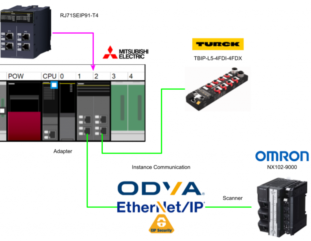
Previously, we built CIP Safety Class 0 communication with the RJ71SEIP91-T4, OMRON NX1-9000 and SL5500, and this time we will use P2 of the RJ71SEIP91-T4 to build a CIP SAFETY Class 0 communication method with TURCK’s TBIP-L5-4FDI-4FDX. The safety programme will be built from scratch and SafetyFB will also be used in GXWORKS3.
Come on, let’s enjoy FA.

Foreword
Thank you from the bottom of my heart for visiting my technical blog and YouTube channel.
We are currently running the “Takahashi Chris” radio show with Full-san (full@桜 八重 (@fulhause) / X) which I deliver every Wednesday night.
Sharing, not hoarding, technical knowledge
We publish technical information related to factory production technology and control systems for free, through blogs and videos.
With the belief that “knowledge should be accessible to everyone,” we share practical know-how and real-world troubleshooting cases from our own field experience.
The reason we keep it all free is simple: to help reduce the number of people who struggle because they simply didn’t know.
If you’ve ever thought:
- “Will this PLC and device combination actually work?”
- “I’m having trouble with EtherCAT communication—can someone test it?”
- “I want to try this remote I/O, but we don’t have the testing environment in-house…”
Feel free to reach out!If lending equipment or sharing your configuration is possible, we’re happy to verify it and share the results through articles and videos.
(We can keep company/product names anonymous if requested.)
How can you support us?
Currently, our activities are nearly all unpaid, but creating articles and videos takes time and a proper testing environment.If you’d like to support us in continuing and expanding this content, your kind help would mean a lot.
Membership (Support our radio show)
This support plan is designed to enhance radio with Mr Full.
https://note.com/fulhause/membership/join
Amazon Gift List (equipment & books for content production)
Lists equipment and books required for content creation.
https://www.amazon.co.jp/hz/wishlist/ls/H7W3RRD7C5QG?ref_=wl_share
Patreon (Support articles & video creation)
Your small monthly support will help to improve the environment for writing and verifying articles.
https://www.patreon.com/user?u=84249391
Just trying to share things that could’ve helped someone—if only they’d known.
Your support helps make knowledge sharing more open and sustainable.
Thank you for being with us.
soup01threes*gmail.com
Technical knowledge shouldn’t be kept to ourselves.
Reference Link
Reference Video
OMRON.Let’s Connect with Turck’s CIP Safety IO
Mitsubishi.Open box with RJ71SEIP91-T4!
MELSEC iQ-R Safety Function Block
Safety FB is a manufacturer-supplied function block certified according to ISO 13849-1:2015 PLe, IEC 62061:2012 SIL3 and IEC 61508:2010 SIL3. Its SafetyFB can be used with the safety CPUs of the MELSEC iQ-R series.

Features
Using SafetyFB offers a number of benefits.
✓Improved productivity and maintainability of safety programmes
The main functions used for programming safety applications are provided as the Safety FB library. The use of Safety FB simplifies safety programmes and improves the productivity and maintainability of safety programmes. It also improves the efficiency of debugging and verification of safety programmes.
✓High safety level applications with safety certification FB
Safety FB is safety certified, which means that safety applications can be built according to ISO 13849-1:2006 PLe, IEC 62061:2012 SIL3 and IEC 61508:2010 SIL3. Users can use Safety FB to develop advanced safety applications, making it easier to obtain safety certification from inspectors for user-developed safety applications.
✓Improved reliability of safety programmes
As the user cannot read the internal logic of the safety FB, it cannot be customised or modified by the user. This increases the reliability of the safety function of the programme, as the safety FB cannot be intentionally modified by intent or mishandling. In addition, as the safety FB and its name cannot be created or changed by the user, the safety FB used can be identified by its name whether it is a certified product or not.
✓Display of diagnostic codes.
Diagnostic codes include error codes and status codes. If the safety FB detects an internal error (including parameter out of range or invalid static reset), it displays an error code. If no errors are detected, the safety FB displays a status code. The diagnostic codes are useful for understanding and debugging the operating status of the safety FB.
✓Ladder and combination
Safety FBs can be used within ladder programmes. By combining common ladders with certified safety functions, users can create safe and flexible safety programmes.
Functions
Input signal/ i_bActivate
i_bActivate sets whether the safety FB is activated or not. If i_bActivate is OFF, all output signal values are set to default values. The Safety Refresh communication status signal for CC-Link IE field networks deactivates the safety FB in the event of a safety station malfunction and prevents unwanted signals from being output.
Reset selection
The reset method for the safety FB can be selected from i_bS_StartReset (after starting the safety FB) or i_bS_AutoReset (after the safety input returns).
Manual reset
With this method, the safety output signal does not immediately switch ON even if the safety input signal is set correctly. With the safety input signal correctly set, the safety output signal is switched ON by switching the safety input signal i_bReset from OFF to ON.
Automatic reset
With this method, the safety output signal is immediately set to ON when the safety input signal is set correctly.
Generic State Diagram
The state of the safety FB transitions according to the state diagram described in the safety FB specification. However, when the operating status of the CPU module is STOP or PAUSE, programme operation is interrupted. Therefore, no state transition takes place.

M+SF_ESTOP_R
This FB is a safety-related FB for monitoring emergency stop buttons and can be used for emergency stop functions (stop category 0).

Input labels
| Variable | Data Type | Description |
| i_bActivate | Bit | Activate safety FB. |
| i_bS_EStopIn | Bit | Input signal from emergency stop buttonON = input signal from the emergency stop button is set to ON. |
| i_bS_StartReset | Bit | Selecting the method of resetting the activated (first time) safety FB |
| i_bS_AutoReset | Bit | Selection of reset method to reset the input signal to ONON = automatic reset |
| i_bReset | Bit | reset input |
Output labels
| Variable | Data Type | Description |
| o_bReady | Bit | Selecting the method of resetting the activated (first time) safety FB |
| o_bS_EStop_Out | Bit | safety contribution |
| o_bError | Bit | ON = Error. |
| o_wDiagCode | Word [signed] | diagnostic code |
State Diagram

Timechat

Implementation
The CIP Safety connection and safety programme will now be Configured.
TURCK Side
It is first built from TURCK’s TBIP-L5-4FDI-4️FDX.

Access WebServer
Access the web server of the Turck CIP Safety module.

Login
Login using the Login button on the right.
Default Password is password.

Done!After Login, there are more items that can be set.

Factory Reset
Initially, Factory Reset the CIP Safety module.
Click Station Configuration>Reset to Factory Defaults.

Etherent/IP Memory Map
This is the Instance number and memory Mapping used for the Normal Ethernet/IP connection of the Turck CIP Safety module.

Install the Tools
Now download Turck’s Safety Configurator from the following website.
Note that you will need a coupon code to download the software and you will need to contact your local Turck Office.
Double-click Install.exe to start the software installation.

Select the language and proceed with Install.

wait a while…

Proceed with Next>.

Agree to the licence and proceed with Next.

Proceed with Next.

Start installation.

wait a while…

Done!

Close the installer.

Next, you will be asked to enter the licence and proceed with Yes.

Select Coupon Code and enter the Coupon Code you used when you downloaded the software earlier.

wait a while…

Done!

Create your project
Start Turck’s Safety Configurator.

Create a new Workspace at File>New>New Workspace.

Set the Workspace storage location.

Check and proceed with OK.

Select the Safety IO Block to be used in the project.

The device used in this case is the TBIP-L5-4FDI-4FDX, so you can either select it directly from the list just mentioned or you can follow the Order Number to select the device.

Choose TBIP-L5-4FDI-4FDX and proceed with Ok.

OK to confirm.

Next, the screen changes to the Safety IO basic settings screen.

Local I/Os can be configured for each IO Port of the Safety IO Blocks.
In this article, all will remain Default.

Now tick the Checkbox under “Show Advanced Settings”.

The CIP Safety-related settings are also displayed on the Properties screen, click on ‘Accept current time’ to set the SCID Time Stamp.
Proceed with Ok when all settings are complete.

Save the project.

Commissioning Wizard
Now start the Commissioning Wizard to connect the device with the CIP Safety Configurator in Turck.

Proceed with Next>.

You can set the authentication User Name and Password for the Safety project.
Of course, the Step is not always necessary, so Skip it if it is not required.
Note that if you set a User and Password, you will be asked for that Validator name and Password when downloading the Safety project.

Initially, the error message “No Connection” is displayed. This is because the Ethernet Interface for the connection between the PC and the device has not yet been set up.

Click Setup Interface.

The Interface Configuration screen appears.

Select Ethernet and click >Search for device.

Done!You have found the CIP Safety IO Module from Turck. Select that Module and proceed with Ok.

Finally, click the Ok button to connect the PC and the device.

Yes to save the Configuration.

Change the Default Password and proceed with Ok.

wait a while…

Done!

OK to proceed.

Please wait a moment while the Module restarts…

Click Finish.

Finally, save the modified Configuration.

Mels Side
First set up the Mitsubishi and RJ71SEIP91-T4 sides.

Create New Project
Start GXWORKS3 and add a new project using Project>New.

The R32SF Safety PLC was used in this article.

To use the Safety PLC, a User name and Password must be set up in the project.

Set Username and Password and proceed with Ok.

Once the project has been created, click Setting Change.

Option to Use Module Label.

Done!The project has been created.

Module Configuration
To configure Hardware Configuration, click on Module Configuration.

This is the Module Configuration screen.

Add R35B
Drop IQ-R Series>Main Base>R35B and add the Base Unit used in this article.

Done!

Add R61P
The next step is to add the power supply module used in this article at Power Suppy>R61P.

Done!

Add PLC into PLC Rack
Drop the R32SF Safety PLC into the CPU Slot.

Done!So We installed the CPU in Rack.

Add R6SFM
CPU Extension>R6SFM to add CPU safety extension units.

Done!

Add RJ71SEIP91-T4
The last step is to Drop Network>RJ71SEIP91-T4 into Slot 1.

Done!

Save the Configuration
The next step is to save the Module Configuration.

OK to proceed.

M+Global
As you have just enabled the Use Module Label setting, a Global Variable List named Label>Global Label>M+Global has been added.

M+Global has now defined labels for the CPUs and modules used in this article (RJ71SEIP91-T4 of course).

Check your Configuration
Convert>Rebuild All once to check for Hardware Configuration problems.

Reset User
Initialise the PLC data and reset all data if you have forgotten the Password on the R32SF Safety PLC body – click Online>User Authentication>Initialize all PLC Data.

Write User Data
Next, in order to write the User Data for this project to the CPU, try writing the User data to the R32SF Safety PLC at Online>User Authentication>Write User information to PLC.

Proceed with Yes.

Proceed further with Yes.

Done!

Write to PLC
Perform Online>Write to PLC to write the Hardware Configuration to the CPU once.

Check RJ71SEIP91-T4 IP Address
Click Diagnosis>System Monitor to check the IP address of the RJ71SEIP91-T4 currently.

Double-click the RJ71SEIP91-T4 module.

You can check the diagnostic information of the RJ71SEIP91-T4 and open the Module Information List Tab.

Detailed information on RJ71SEIP91-T4 is displayed and P1=192.168.250.11 is confirmed.

Configure Ethernet/IP Network
Next, to set up an Ethernet/IP network, double-click RJ71SEIP91-T4>CIP Safety Configuration Tool to start the tool.

Install EDS File
Install the EDS File at CIP Configuration Tools>Device Library>Add EDS.

The Add EDS File screen appears.

“Add EDS From Directory and Sub Directory”>Browse to set the Folder where the EDS File is stored.

Proceed with Next>.

If you want to install an EDS File of them, proceed with Next>.

Done!

EDS File has been installed.

Start Detection
Network Detection>Start Network detection to search for Ethernet/IP devices in the network.

OK to proceed.

wait a while…

Done!We found TBIP-L5-4FDI-4️FDX from TURCK.

Right-click TBIP-L5-4FDI-4️FDX>Insert in Configuration to add TBIP-L5-4FDI-4️FDX to your network Configuration.

Done!

Check Ping
Check Send Ping function communication.

Infomration
Update and reconfirm TBIP-L5-4FDI-4️FDX information in the Infomration Tab.

Safety Settings
Set the parameters required to build a Safety Connection.
Safety Parameters
Select the TBIP-L5-4FDI-4️FDX you have just added>Safety Settings>Safety Parameters Tab.

Signature in Device
Check the SNCT of the TBIP-L5-4FDI-4️FDX in TURCK: click on the Refresh button in the Signature in Device section to get the SNCT on the device.

Cpoy the Signature
Click on the Copy button to duplicate the SNCT set in the device itself.

Paste to Configuration
Click on the ‘Paste’ button under ‘Signature in SNCT’.

Done!

Configuration Type
The configuration of the TURCK module will be done in a separate tool, so set the Configuration Type to “Externally Initialized”.

Safety Connection
Next, open the Safety Conenction Tab.

Check Type
Set Check Type to Compatible Module.

Connection Type
Next, set the Connection Type to match your application. In this article, Deafult will be set, so there is no need to change it.

Configure Safety Label
Click Safety Communication Module>CPU Data Exchange to set the Module Label for data exchange between TBIP-L5-4FDI-4️FDX and RJ71SEIP91-T4.

This is the Label and device configuration screen for the RJ71SEIP91-T4 and each CIP Safety connection.

Sets the device label for the data exchanged with TURCK’s TBIP-L5-4FDI-4️FDX.

Export Label to GxWorks3
Finally, click on the “GxWorks3 Copy Labels” button to paste the mapping settings set in the tool into the GxWorks3 project.

Label>Global Label>right-click>Add New Data.

Set Safety in the Category item.

Enter the Global Label List name and confirm with OK.

Done!

Open the Safety Global Label List and click ‘Show Details’.

Open the Safety Global Label List and click ‘Show Details’.

Done!

Listing
Click Configuration>Listing to check the CIP Safety settings built in this RJ71SEIP91-T4.

Done!

Safety Operation
The next step is to operate the Safety settings for Network 2.

Safety Reset
Safety>Safety Reset to reset Port 2 of RJ71SEIP91-T4.

Click Reset.

Proceed with Yes.

Done!

Restart the PLC.

Edit TUNID
Click the Edit button to set the TUNID of Port 2 of the RJ71SEIP91-T4.

It can be set either Time-based or manually, in this case the TUNID is set manually.

Set TUNID
Finally, click on the Set TUNID button to set the TUNID of the RJ71SEIP91-T4 P2.

Done!

Download Configuration
Download Configuration to Network2.

Configure Safety Cycle Time
Next, the Safety Cycle Time needs to be matched to the Mitsubishi Safety PLC and the RJ71SEIP91-T4. The Safety Cycle time is calculated on the Tab in Timings to 13.3 ms and the CIP Configuration Tools.

Click R32SFCPU>CPU Parameter.

In Safety Factory Setting>Safety Cycle Time, set a smaller Cycle Time than the one automatically calculated in the CIP Configuration Tools earlier.

Add Shared GVL
Next, add a Global Label List for Standard/Safety Shared.


NonSafety-Program
Create a non-safety program.

The RJ71SEIP91-T4 acquires the communication start signal and the status of each connection as shown in the figure below.

| RJ71SEIP91_1.stEIPCls1_P1.uSet_CommunicationStartupRequest_D:=1; RJ71SEIP91_1.stEIPCls1_P2.uSet_CommunicationStartupRequest_D:=1; gModuleOK:=RJ71SEIP91_1.bSts_ModuleReady; gConnection528OK:=RJ71SEIP91_1.stCIP_Safety_P1.bnDataLinkStatus_Out_D[1]; gConnection529OK:=RJ71SEIP91_1.stCIP_Safety_P1.bnDataLinkStatus_In_D[2]; gConnection3TURCKOK:=RJ71SEIP91_1.stCIP_Safety_P2.bnDataLinkStatus_In_D[3] and RJ71SEIP91_1.stCIP_Safety_P2.bnDataLinkStatus_Out_D[3]; fbTON1(IN:= gReset ,PT:= T#1s ); IF fbTON1.Q THEN gReset:=FALSE; END_IF; ; |
Add Safety Library
Add the Safety Library to the GX WORKS3 project.

M+SF_ESTOP_R_01A of SafetyFB is used in this case.

Right click on the appropriate SafetyFB>Add to Project>Create FB File.

Done!

If you want to use a SafetyFB, drop that FB on the Safety ladder.

Sets the Instance name for SafetyFB.

Done!At the end of the process, just connect the inputs and outputs as you would for a normal FB.

Safey Program
Now to create a safety program, Fixed Scan>Right click>Add New Data.

Select Category as Safety.

Set Data type to Program Block.

Mitsubishi’s safety program can be created with Ladder only.

Done!

Here is the safety program created by Mitsubishi for this project.

Rung1
Rung checks if the RJ71SEIP91-T4 module is in good condition and also checks if the communication with TURCK’s TBIP-L5-4FDI-4️FDX is OK.

Rung2/3
Rung2/3 delays the emergency stop signal received from TURCK’s TBIP-L5-4FDI-4️FDX via CIP Safety communication before using it in the program.

Rung4-9
Run 4-9 uses SafetyFB to control emergency stops provided by Mitsubishi Electric.
Rung10/11
Once Rung 10/11 confirms that the emergency stop is OK, it sends an ON signal to TURCK’s TBIP-L5-4FDI-4️FDX via CIP Safety to turn Port5 ON.

Write
Download your project to the CPU by going to Online>Write to PLC.

Reset Power
Finally, turn the IQ-R CPU back on.
Result
This is the actual product!

RJ71SEIP91-T4 is currently error free on P1 and P2, and is also lit on Safety COM RUN and NS.

Both MS and NS LEDs on TURCK’s TBIP-L5-4FDI-4FDX body are lit green.

First we want to check the communication status from the CIP Configuration Tools of GXWROKS3, so select Network2 and click >Start Diagnosic.

OK to proceed.

The green ICON next to TURCK’s TBIP-L5-4FDI-4️FDX indicates that the RJ71SEIP91-T4 and TBIP-L5-4FDI-4️FDX are communicating normally.

Let’s check from TURCK’s Safety Configuration Tool this time: the ON command sent from RJ71SEIP91-T4 was also received.


GXWROKS3 received the TBIP-L5-4FDI-4️FDX signal as well.

The emergency stop SafetyFB is also working properly.

This is the LED status when the RJ71SEIP91-T4 is communicating normally with CIP Safety.
You can check the actual operation in this video.