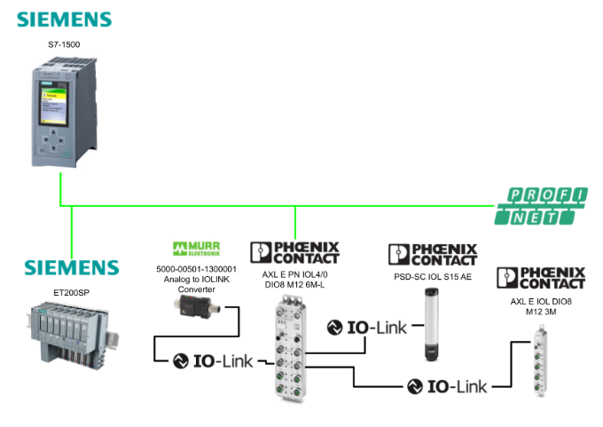
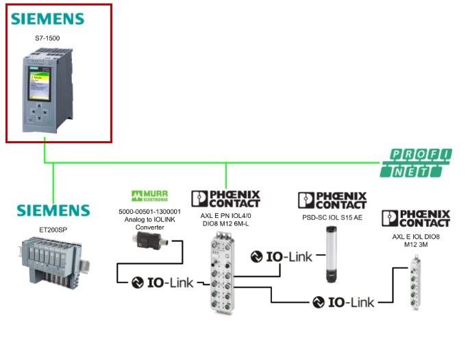
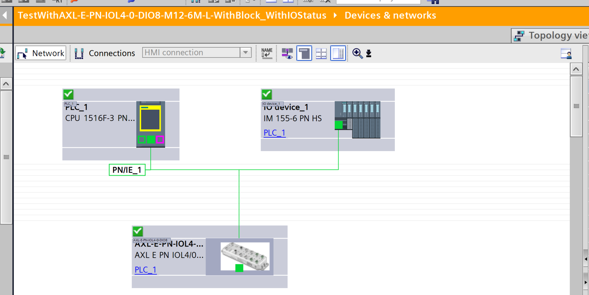
In this article, we will not only explain how to connect the Siemens S7-1500 and the Phoenix Contact AXL E PN IOL4/0 DIO8 M12 6M-L via PROFINET, but also how to use the Siemens standard library “LIOLink” to dynamically override the parameters of the AXL E IOL DIO8 M12 3M from within the program.
The IO-Link devices used in this article are as follows:
- AXL E IOL DIO8 M12 3M
- PSD-SC IOL S15 AE
- Murrelektronik 5000-00501-1300001
(Converter that converts analog signals to IO-Link)
Alright, let’s enjoy the FA!
Foreword
Thank you from the bottom of my heart for visiting my technical blog and YouTube channel.
We are currently running the “Takahashi Chris” radio show with Full-san (full@桜 八重 (@fulhause) / X) which I deliver every Wednesday night.
Sharing, not hoarding, technical knowledge
We publish technical information related to factory production technology and control systems for free, through blogs and videos.
With the belief that “knowledge should be accessible to everyone,” we share practical know-how and real-world troubleshooting cases from our own field experience.
The reason we keep it all free is simple: to help reduce the number of people who struggle because they simply didn’t know.
If you’ve ever thought:
- “Will this PLC and device combination actually work?”
- “I’m having trouble with EtherCAT communication—can someone test it?”
- “I want to try this remote I/O, but we don’t have the testing environment in-house…”
Feel free to reach out!If lending equipment or sharing your configuration is possible, we’re happy to verify it and share the results through articles and videos.
(We can keep company/product names anonymous if requested.)
How can you support us?
Currently, our activities are nearly all unpaid, but creating articles and videos takes time and a proper testing environment.If you’d like to support us in continuing and expanding this content, your kind help would mean a lot.
Membership (Support our radio show)
This support plan is designed to enhance radio with Mr Full.
https://note.com/fulhause/membership/join
Amazon Gift List (equipment & books for content production)
Lists equipment and books required for content creation.
https://www.amazon.co.jp/hz/wishlist/ls/H7W3RRD7C5QG?ref_=wl_share
Patreon (Support articles & video creation)
Your small monthly support will help to improve the environment for writing and verifying articles.
https://www.patreon.com/user?u=84249391
Paypal
A little help goes a long way.
https://paypal.me/soup01threes?country.x=JP&locale.x=ja_JP
Just trying to share things that could’ve helped someone—if only they’d known.
Your support helps make knowledge sharing more open and sustainable.
Thank you for being with us.
soup01threes*gmail.com
Technical knowledge shouldn’t be kept to ourselves.
Reference Link
FB
This article explains the standard Siemens functions used here.
SCALE_X: Scale
The “Scale” instruction allows you to map the value of the VALUE input to a specified range and scale it. When the “Scale” instruction is executed, the floating-point value of the VALUE input is scaled to the range defined by the MIN and MAX parameters. The result of the scaling is an integer, which is stored in the RET_VAL output.
The following figure shows an example of how to scale values.
The “Scale” command operates using the following formula:
OUT = [VALUE ∗ (MAX – MIN)] + MIN |
|---|
Parameters
The following table lists the parameters for the “Scale” command.
Parameters | Declaration | Data type | Memory area | Description |
|---|---|---|---|---|
MIN | Input | Integers, floating-point numbers | I, Q, M, D, L, or a constant | Lower limit of the value range |
VALUE | Input | floating-point numbers | I, Q, M, D, L, or a constant | The value to be scaled. If you are entering a constant, it must be declared. |
MAX | Input | Integers, floating-point numbers | I, Q, M, D, L, or a constant | Upper limit of the value range |
RET_VAL | Output | Integers, floating-point numbers | I, Q, M, D, L | Scaling Results |
NORM_X: Normalize
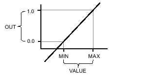
The “Normalize” command allows you to map the values of tags supplied to the VALUE input onto a linear scale to normalize them.
- Use the MIN and MAX parameters to define the range of values applied to the scale.
- The RET_VAL output outputs and saves the result, calculated based on the position of the value to be normalized within this range, as a floating-point number.
- If the value to be normalized is equal to the MIN input value, the OUT output will be “0.0”.
- If the value to be normalized is equal to the MAX input value, the OUT output will be “1.0”.
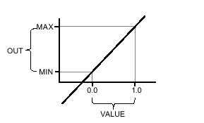
The following figure shows an example of how to normalize values.
The “Normalize” command operates based on the following formula.
OUT = (VALUE – MIN) / (MAX – MIN) |
|---|
Parameters
The following table shows the parameters for the “Normalize” command.
Parameters | Declaration | Data type | Memory area | Description |
|---|---|---|---|---|
MIN | Input | Integers, floating-point numbers | I, Q, M, D, L | Lower limit of the value range |
VALUE | Input | Integers, floating-point numbers | I, Q, M, D, L | Normalized values |
MAX | Input | Integers, floating-point numbers | I, Q, M, D, L | Upper limit of the value range |
RET_VAL | Output | floating-point number | I, Q, M, D, L | Normalization results |
Operating mode:Filling Level Mode
PSD-SC IOL S15 AEのFilling Levelでは、アナログ値がシグナルタワーによって表示されまThe filling level of the PSD-SC IOL S15 AE is displayed as an analog value via a signal tower. Each segment serves as an indicator of the filling level, with the range represented by 0% when all segments are off and 100% when all segments are on.
This allows for the accurate visualization of order progress or the presence of materials in the machine process as a rising or falling illuminated display.
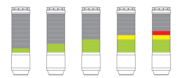
Color settings are configured using the global parameter “Filling Level Mode.” There are two available options:
- Apply settings for segments 1–15 or 1–9
-
Apply settings for segment 1
Process Data: Fill Level Mode
8-bit process data is processed.The valid range is 0 to 100.
ビット | 7 | 6 | 5 | 4 | 3 | 2 | 1 | 0 |
|---|---|---|---|---|---|---|---|---|
0 ~ 100(%) |
SIMATIC S7-1500/1200 IO-Link Library (LIOLink)
The IO-Link communication standard opens up new possibilities by intelligently connecting sensors and switching devices to the controller level. The core elements are switching, protection, and monitoring at the field level.
An IO-Link system consists of an IO-Link master and one or more IO-Link devices (sensors or actuators). The IO-Link master acts as an interface to the higher-level controller and controls communication with the connected IO-Link devices.
The IO-Link library provides blocks and PLC data types to facilitate communication between SIMATIC controllers and IO-Link masters or IO-Link devices.
Scope of Functions
The blocks included in this library are categorized into the following four groups.
- General-purpose base block
This is a basic block used for communication with SIMATIC IO-Link masters and all IO-Link devices, as well as for reading IO-Link diagnostic information. - Master-Only Block
This block is used to back up and restore the SIMATIC IO-Link master, as well as to execute port functions. - Device-specific block
To simplify communication with specific IO-Link devices, these blocks feature interfaces optimized specifically for each device and predefined PLC data types. These blocks are based on the base block. - Profile Block
These blocks simplify device communication via specific IO-Link profiles. They are also based on the base blocks.
Scope of validity
This library is available in TIA Portal V18 and later versions. All blocks in the library can be used with SIMATIC S7-1200 and S7-1500 controllers.
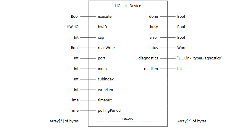
LIOLink_Device
In this article, we will use this FB to overwrite the parameters of the IOLink device.
List of Parameters
Control and Configuration Systems
Name | Type | Data type | Description |
|---|---|---|---|
execute | IN | Bool | Request to execute a function |
hwID | IN | HW_IO | Hardware identifier of the IO-Link master or the first submodule |
cap(Any) | IN | Int | Access Point (Client Access Point) – This is not normally required when using a Siemens IO-Link master, as the device is automatically detected. If this parameter is changed, automatic detection will not occur. |
readWrite | IN | Bool | Mode setting: FALSE: Read; TRUE: Write |
port | IN | Int | Valid range of port numbers to which IO-Link devices are connected: 0–63 |
index | IN | Int | Parameter index valid range: 0..3276765535 (0xFFFF): IOL-D port functions |
subindex | IN | Int | Parameter subindex 0: Entire record; 1–255: Parameters within the record |
writeLen | IN | Int | Write data length (bytes, net data) Valid range (during write): 1–232; irrelevant during read |
timeout | IN | Time | The time until the command is canceled |
pollingPeriod(Any) | IN | Time | Variable wait time during which the block waits for the dataset to be sent. Default value: 100 ms |
Status-related
Name | Type | Data type | Description |
|---|---|---|---|
done | OUT | Bool | TRUE:The command executed successfully |
busy | OUT | Bool | TRUE:Processing command |
error | OUT | Bool | TRUE:An error occurred while processing FB |
status | OUT | Word | 16#0000–16#7FFF: FB status 16#8000–16#FFFF: Error code |
Data and Diagnostics
Name | Type | Data type | Description |
|---|---|---|---|
diagnostics | OUT | “IOLink_typeDiagnostics” | Detailed diagnostic information for FB |
readLen | OUT | Int | Length of read data (bytes, net data) |
record | IN_OUT | Array[*] of bytes | Valid range of the read/write data transmission and reception buffers: 0..231 |
How It Works
Addressing
The target dataset is uniquely identified by the “index” and “subindex” parameters.
When writing data, the amount of data specified by the “writeLen” parameter is sent to the IO-Link device. This parameter is irrelevant during read operations.
The access point to the IO-Link master is defined by the “cap” parameter (Client Access Point). When using an IO-Link master manufactured by Siemens AG, detection occurs automatically. However, changing this parameter disables automatic detection. Typically, the access point is 0xB400 or 0x00E3.
Communication Time Series
Data communication begins when a rising edge is detected on the “execute” input.
The “done”, “busy”, “error”, and “status” outputs indicate the command execution status.
After successful execution, the “len” parameter displays the length of the received or written data.
The output parameters retain their values while the “execute” input is set.
Even if the “execute” input is reset before the FB processing is complete, the values of the output parameters will be output for one cycle after command processing.
If the processing time exceeds the time specified by the “timeout” parameter, processing is interrupted and an error is output.
Note
Data is transferred in the form of raw data (an array of bytes). Therefore, the data cannot be interpreted directly in this state.
The user must format and interpret the data in accordance with the device manufacturer’s specifications (e.g., by copying it into data structures or data types).
Error Handling
The “status” output displays the current status and any error conditions. Meanwhile, the “diagnostics” output provides a diagnostic structure containing detailed information when an error occurs.
Status | Meaning |
|---|---|
16#0000 | Processing completed successfully. No warnings, no additional information. |
16#7000 | No operation in progress (initial value) |
16#7001 | First call of a new command (rising edge of “execute”) |
16#7002 | Second or subsequent call |
16#8201 | Unsupported port |
16#8202 | Unsupported index |
16#8203 | Unsupported subindex |
16#8205 | Length of “writeLen” parameter does not match the data set to be written |
16#8401 | IO-Link master reported an error code (see “diagnostics” for details) |
16#8402 | Received data set does not match the operation |
16#8403 | Processing could not be completed within the specified time |
16#8600 | Internal state machine reached an undefined state |
16#8601 | System function WRREC reported an error |
16#8602 | System function RDREC reported an error |
Diagnosis
If an error occurs, the “diagnostics” output provides detailed information about the current pending error.
Tag | Description |
|---|---|
status | The most recent status code from the “status” interface parameter of the FB |
subfunctionStatus | Error code status from system function RDREC/WRREC or the IO-Link master (%W1: IO-Link master error code, %W0: ISDU error code). For details, refer to the online help of the relevant system function, or the IO-Link master/device manual. |
stateNumber | State number of the state machine within the FB at the time the error occurred |
Implementation
Siemens Side
First, we will set up the Siemens S7-1500 side.
Library Downloads
To use the Siemens LIOLINK library, please download it from the link below.
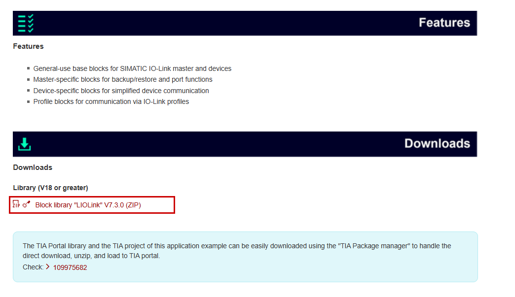
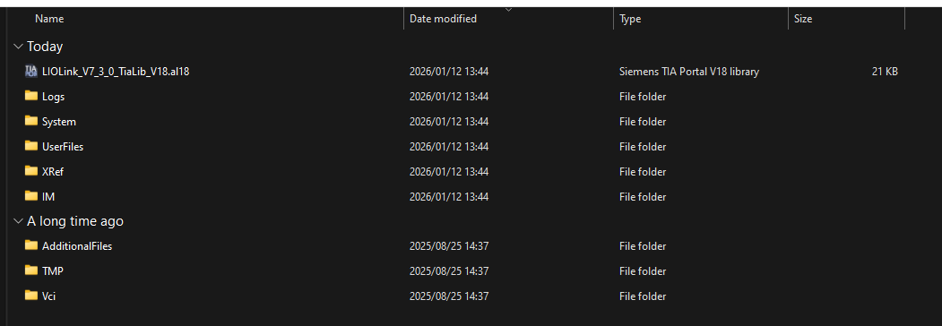
Next, unzip the downloaded ZIP file.
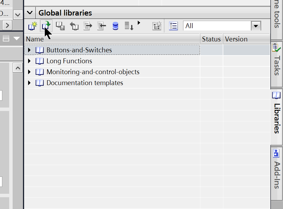
Open TIA, go to the Global Library, and click the button shown in the figure below.
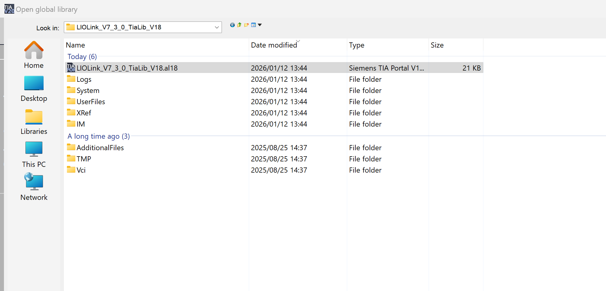
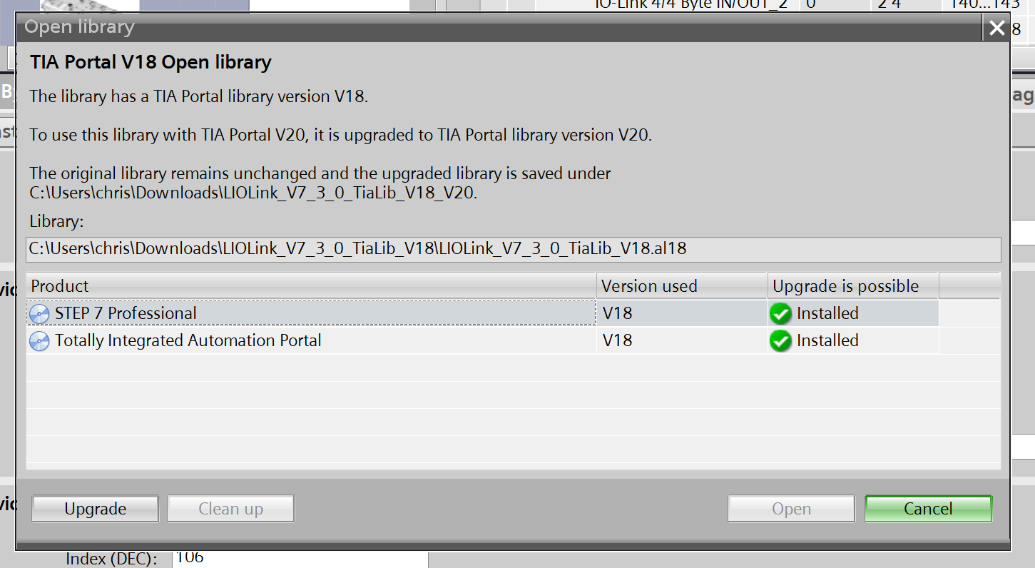
Open the .al18 file in the folder you just extracted.
Since we’re using TIA V20 for this article, click the “Upgrade” button.
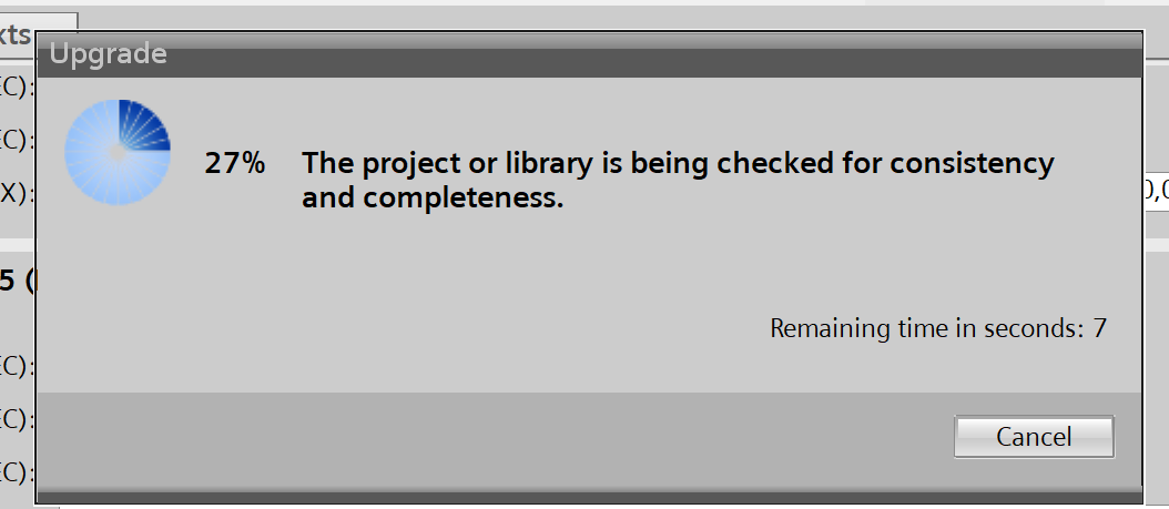
Please wait a moment…
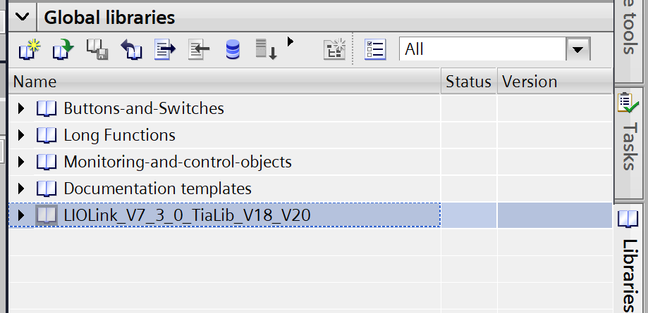
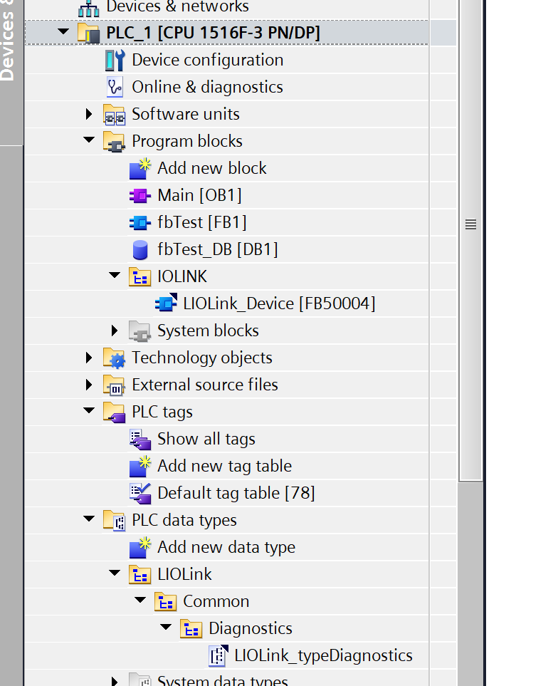
Done!The LIOLINK library has been added.
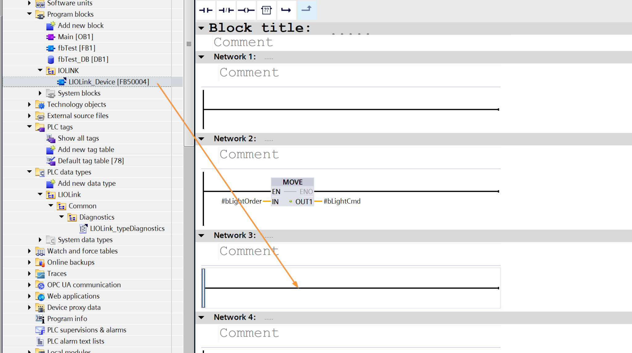
Next, add Base blocks→LIOLink_Device to the project.
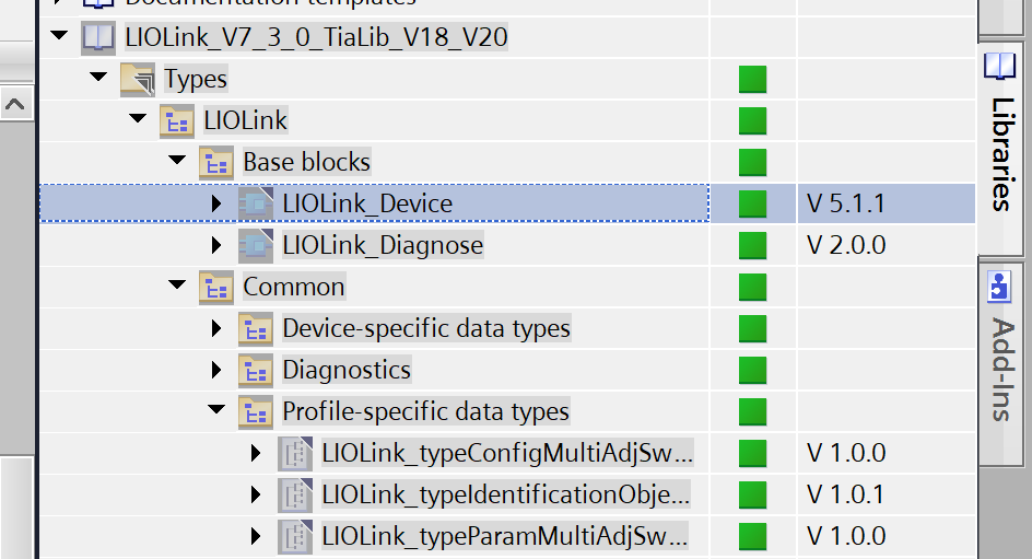
Done!
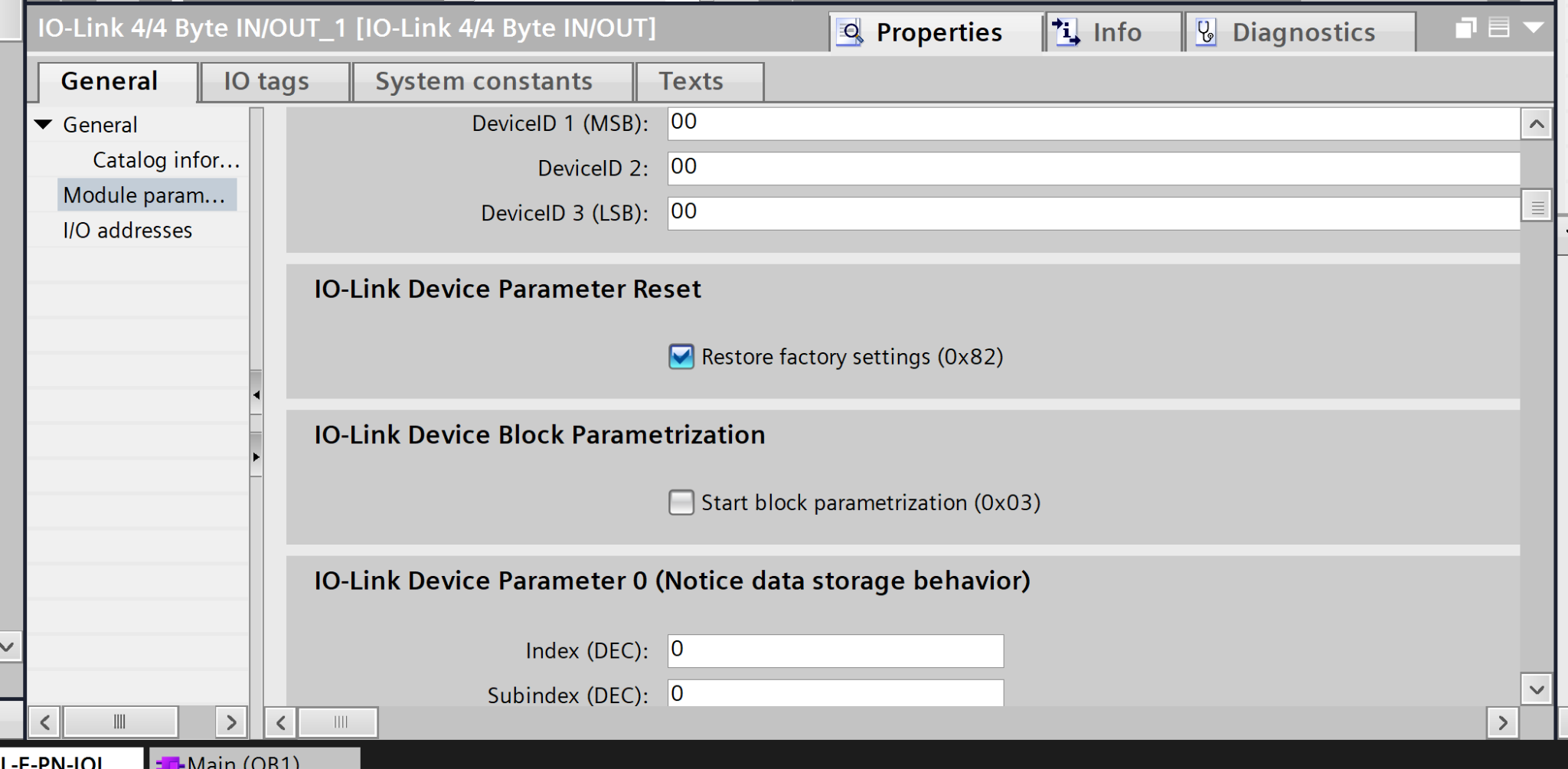
AXL E IOL DIO8 M12 3M-IO-Link Parameters
In the previous article, we set up the AXL E IOL DIO8 M12 3M and configured the initial parameters. In this article, by checking the “Restore factory settings” checkbox below, the parameters will be reset to their default values every time the AXL E IOL DIO8 M12 3M is used.
Program
Next, we’ll write the program.
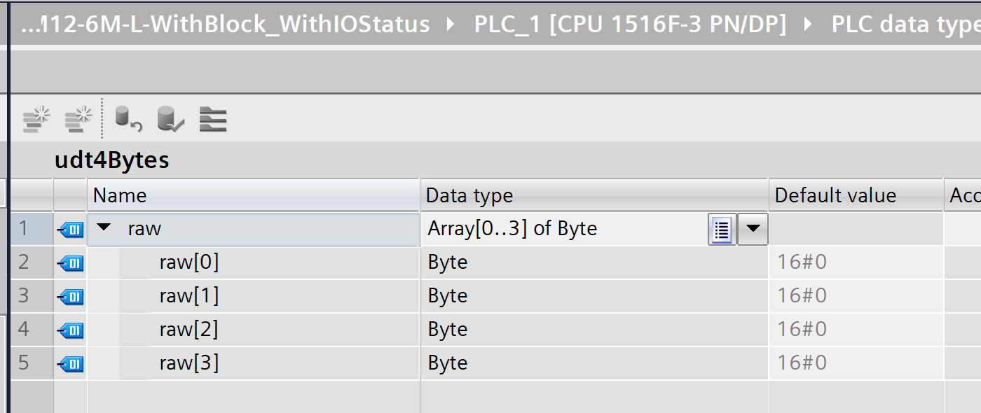
udt4Bytes
The data type is named `udt4Bytes` and is structured to hold 4 bytes of raw data internally.
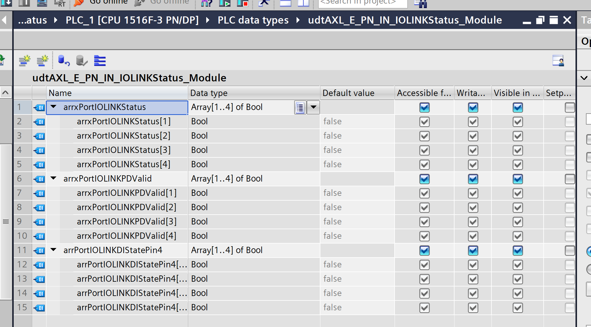
udtAXL_E_PN_IN_IOLINKStatus_Module
This UDT is a status data type designed to handle the status of each port on the IO-Link module collectively. It stores the status of each port (1–4) in a Boolean array, organized by application.
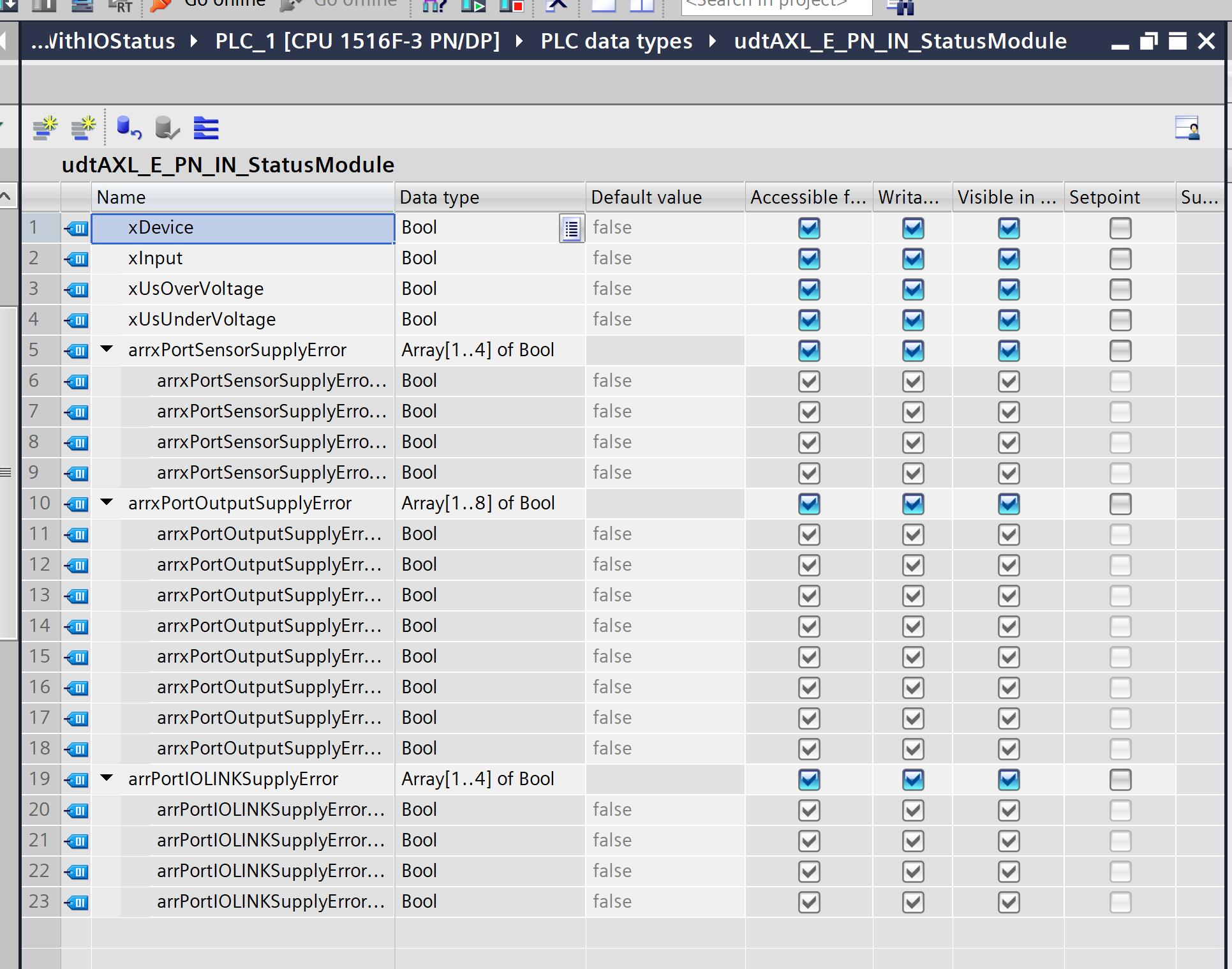
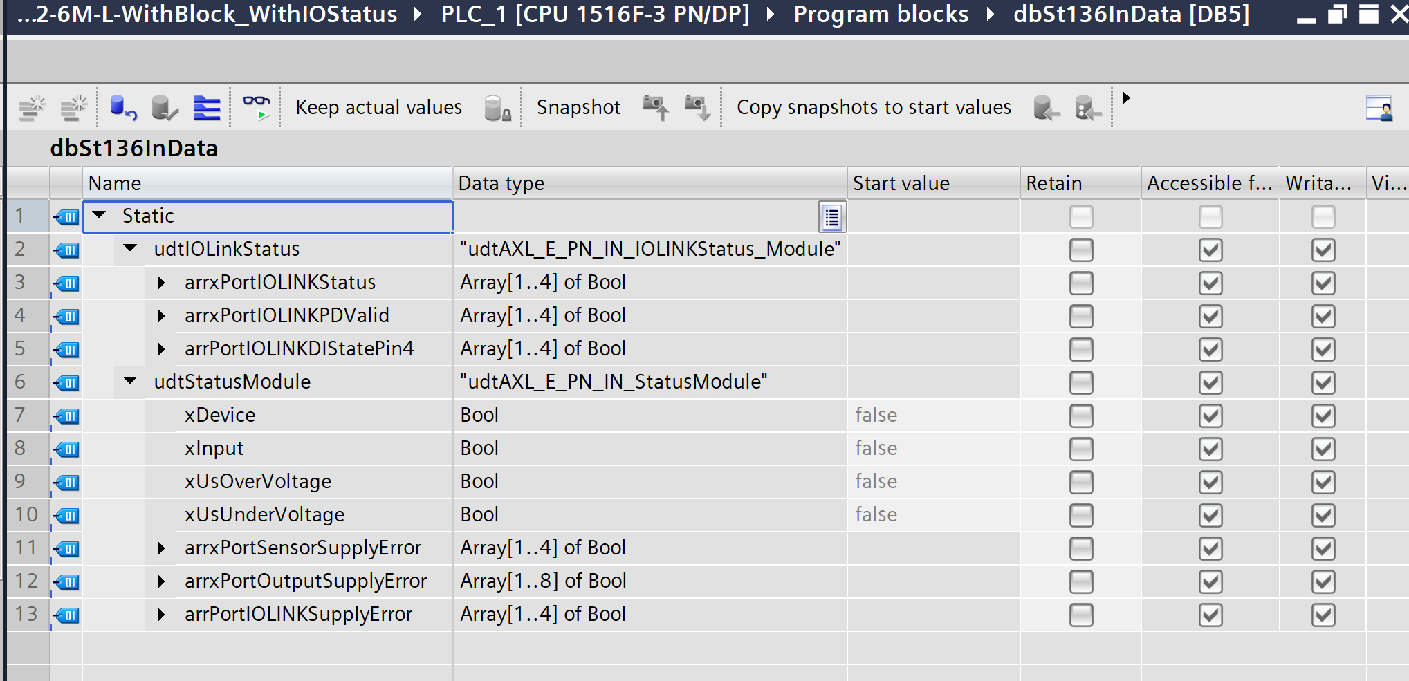
udtAXL_E_PN_IN_StatusModule
This UDT is a status data type designed to aggregate and store information regarding the power supply, device status, and error status of each port on the entire IO-Link module.
It consolidates all the information needed to determine whether the module is currently functioning normally in a single location.
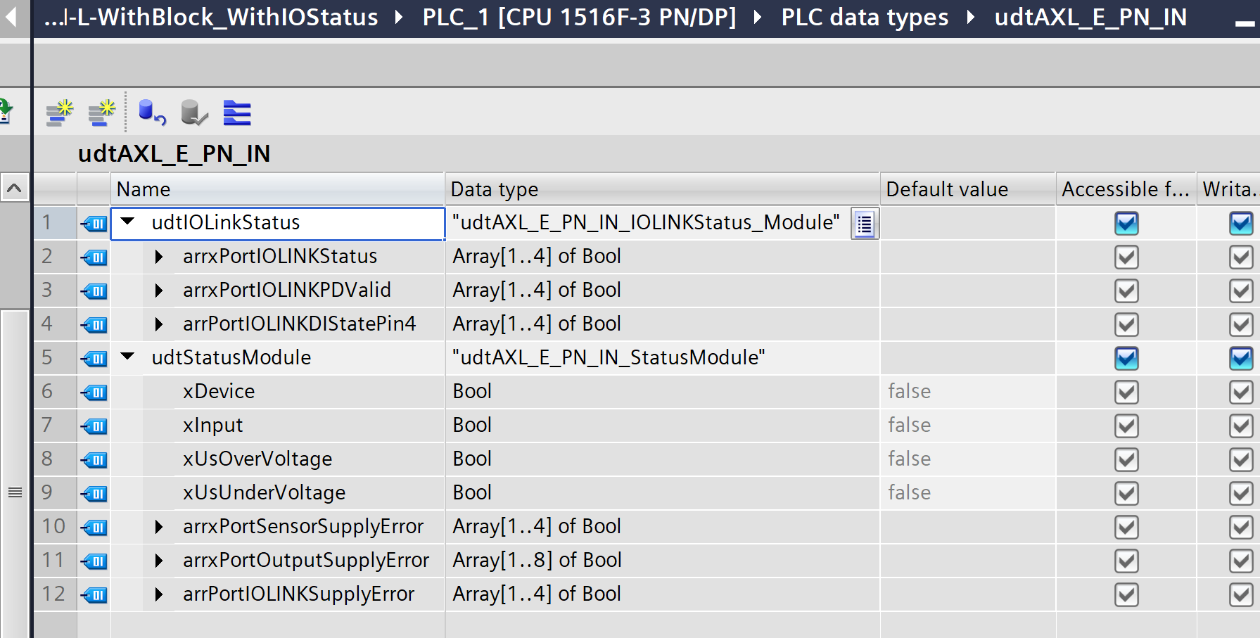
udtAXL_E_PN_IN
This UDT encompasses the two status UDTs we have seen so far and serves as a data type for treating the entire state of the AXL E PN IN module as a single structure.
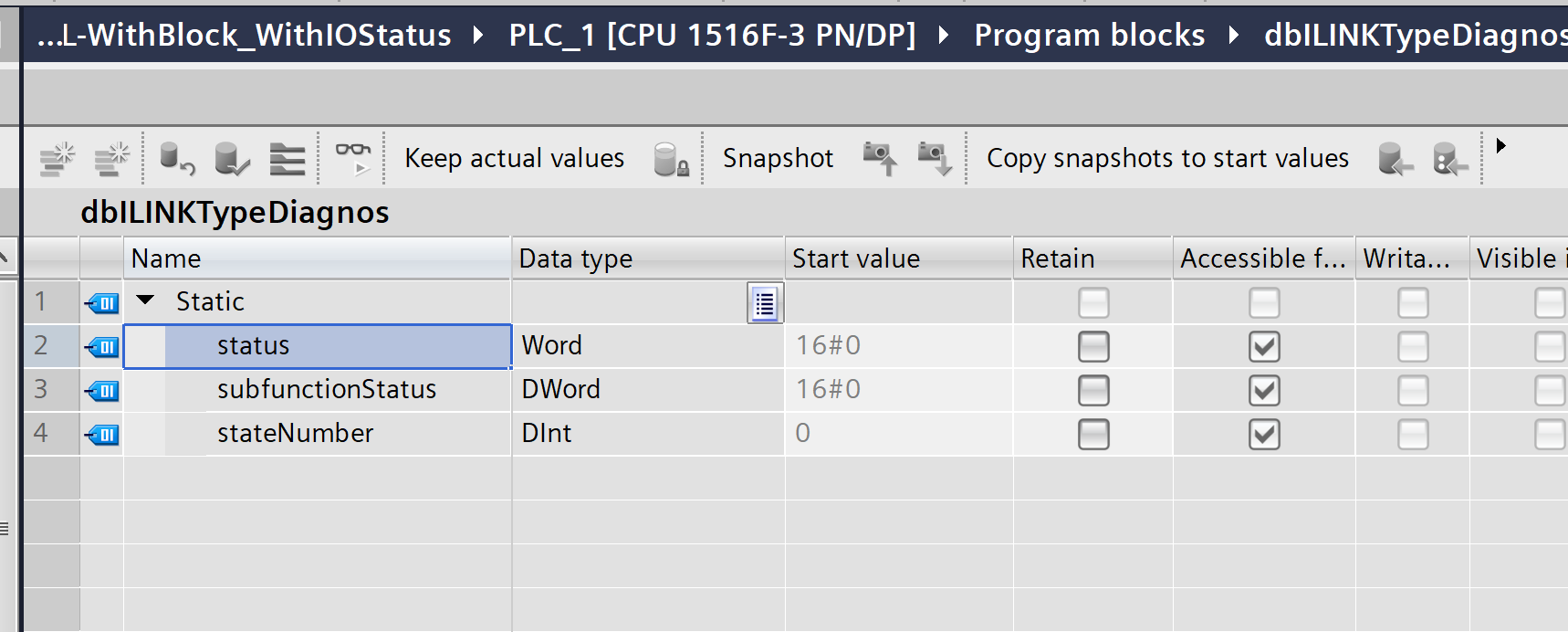
dbILINKTypeDiagnos
Create a Data Block and set the Type to LIOLink_typeDiagnostics.
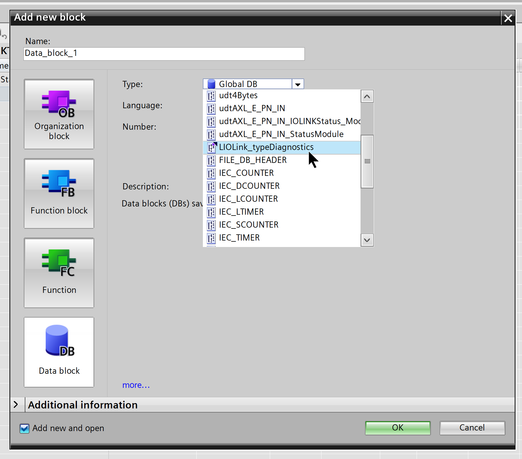
Done!
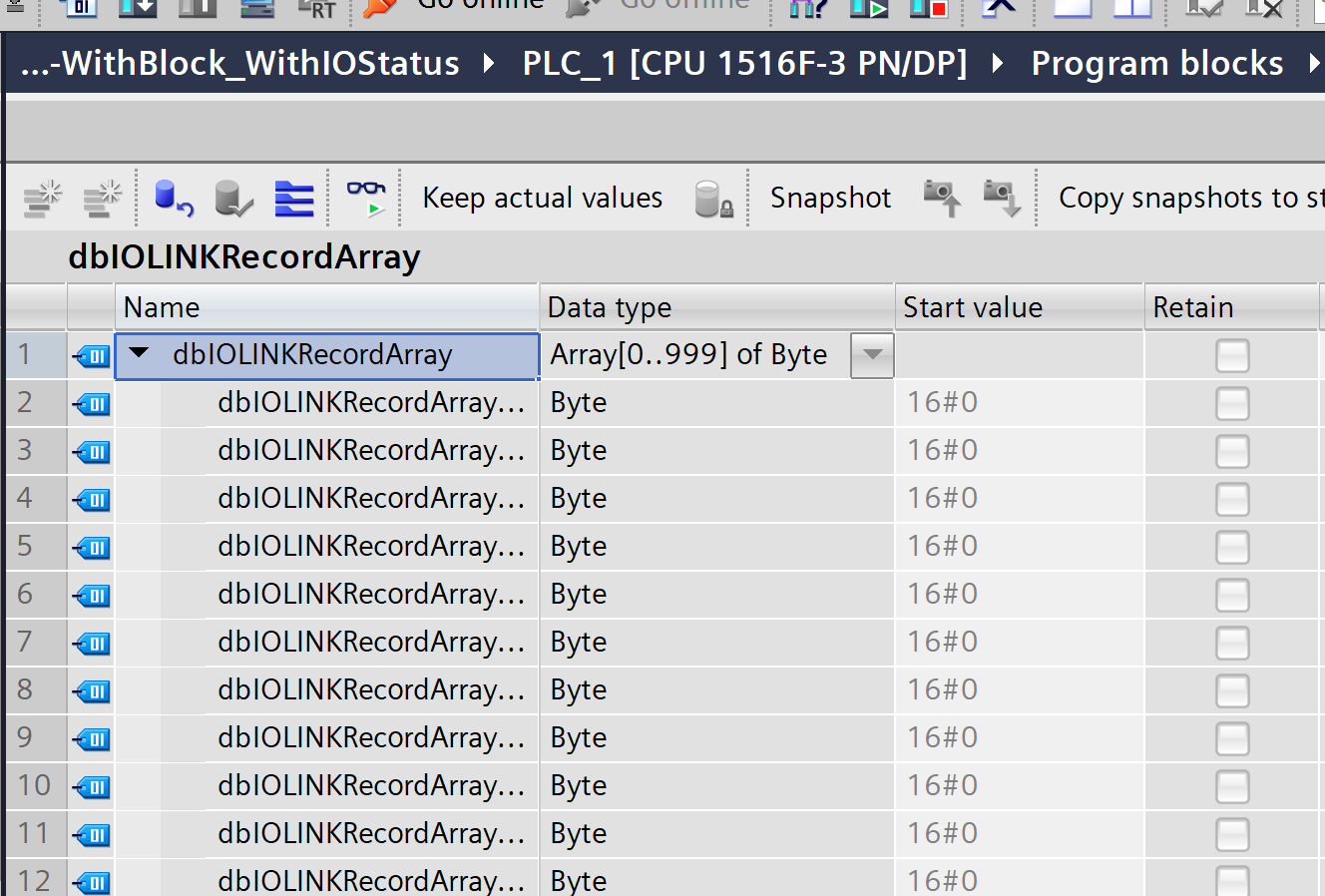
dbIOLINKRecordArray
This is a database that defines a byte array of length 1000.
dbSt136InData
This is the database that parses and stores input data for the AXL E IOL DIO8 M12 3M.
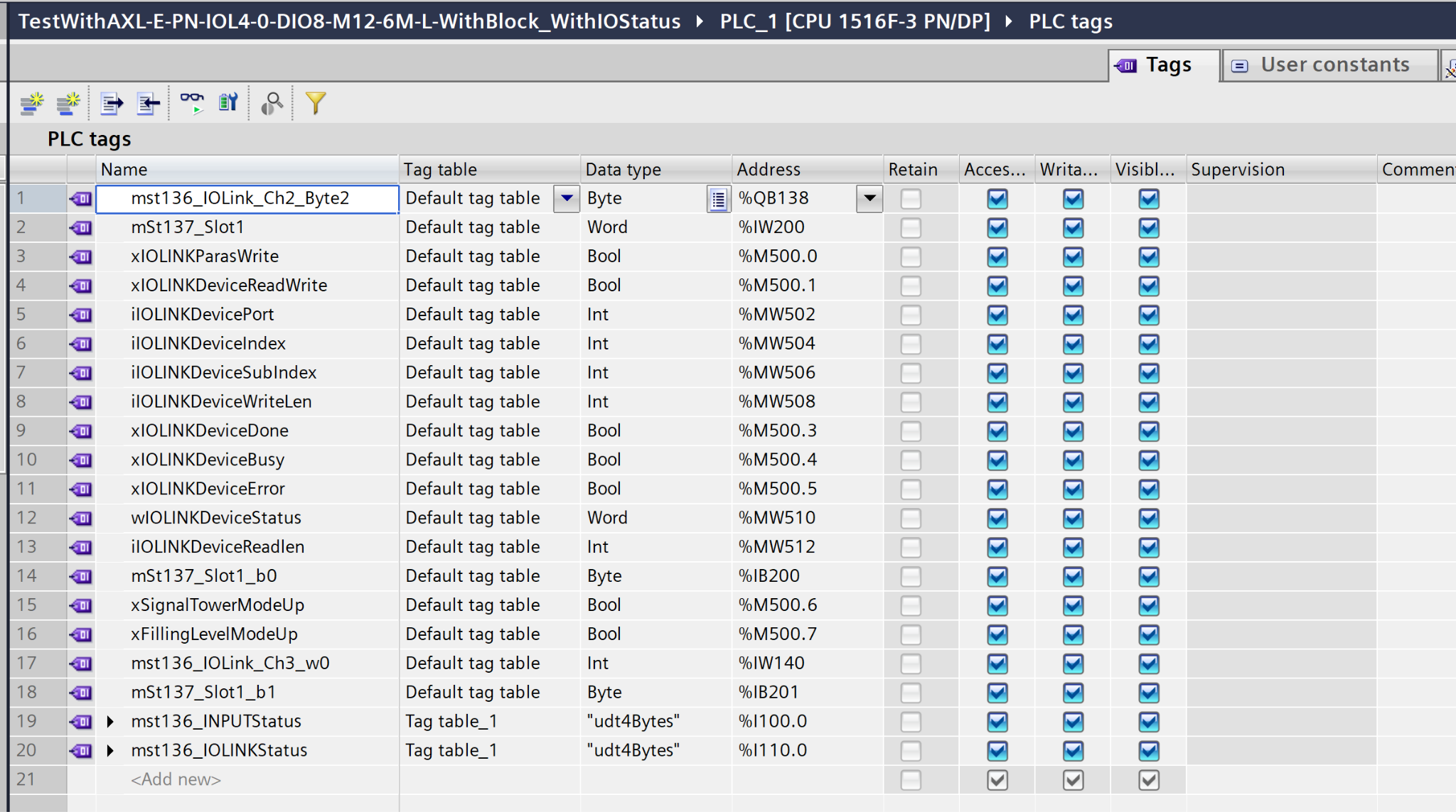
PLC Tags
These are the tags defined in this article.
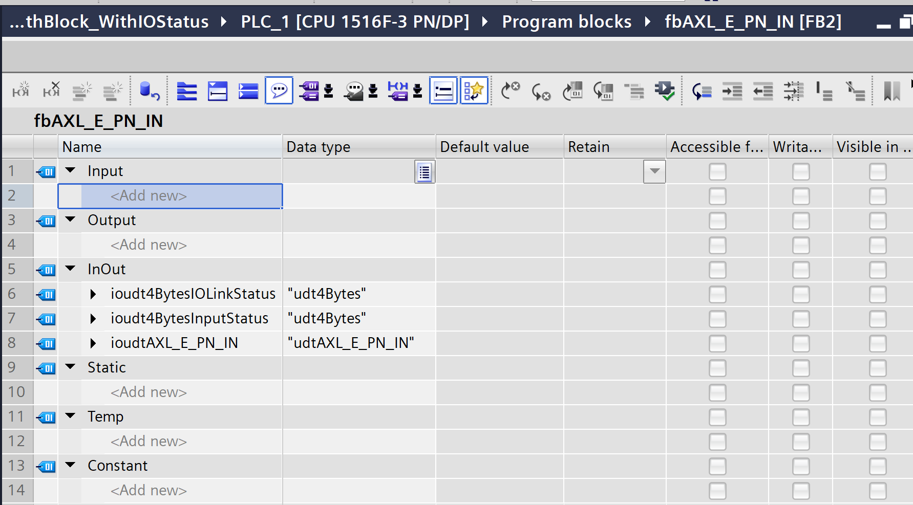
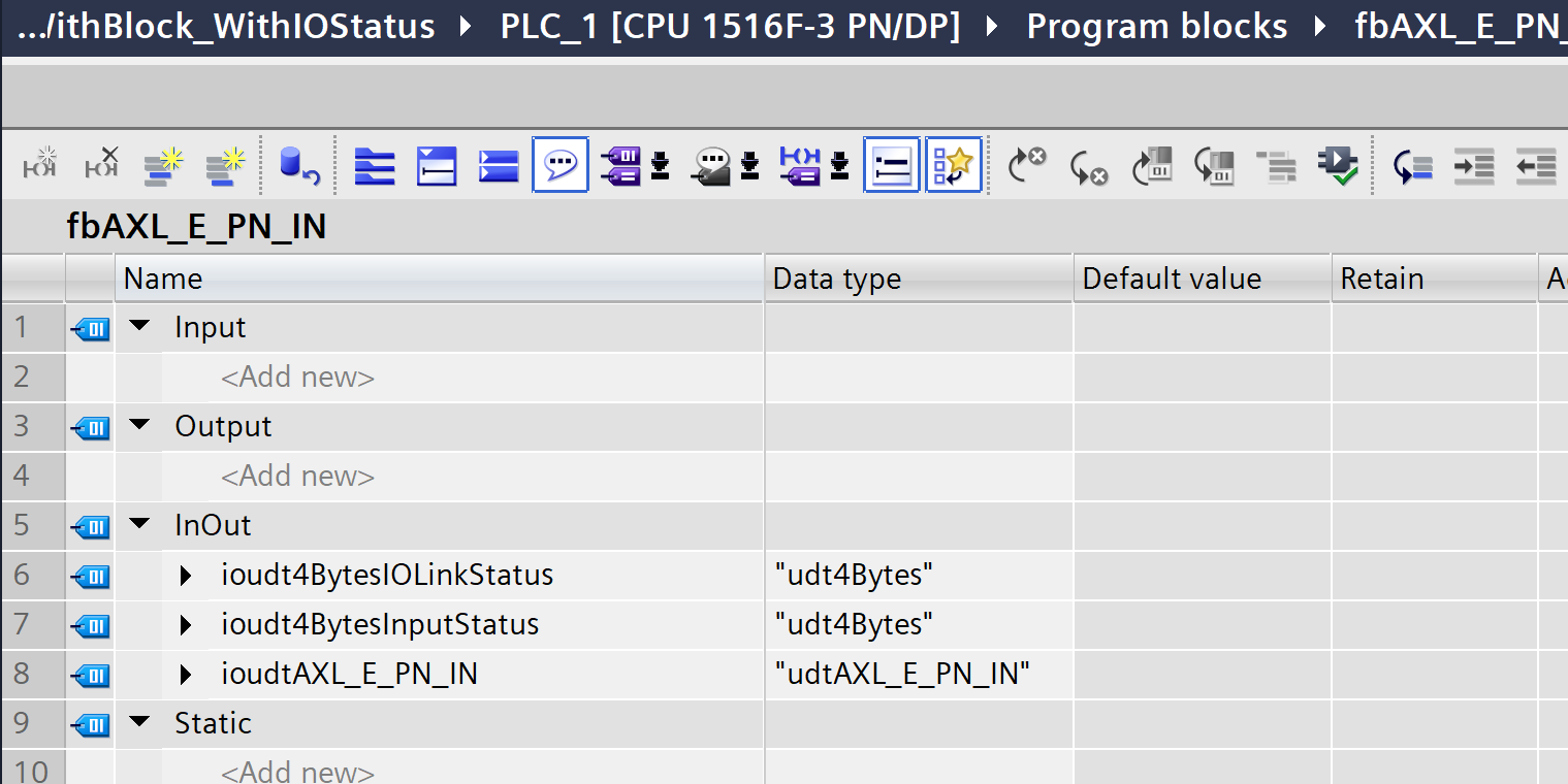
fbAXL_E_PN_IN
This FB parses and stores the input data from the AXL E IOL DIO8 M12 3M.
It accepts the raw status data (IOLinkStatus/InputStatus) received from IO-Link as input, converts it into the structured status (udtAXL_E_PN_IN) for the AXL E PN IN module, and outputs it.
VAR
This is the Block interface.
Prgoram
Next, let’s write a program.
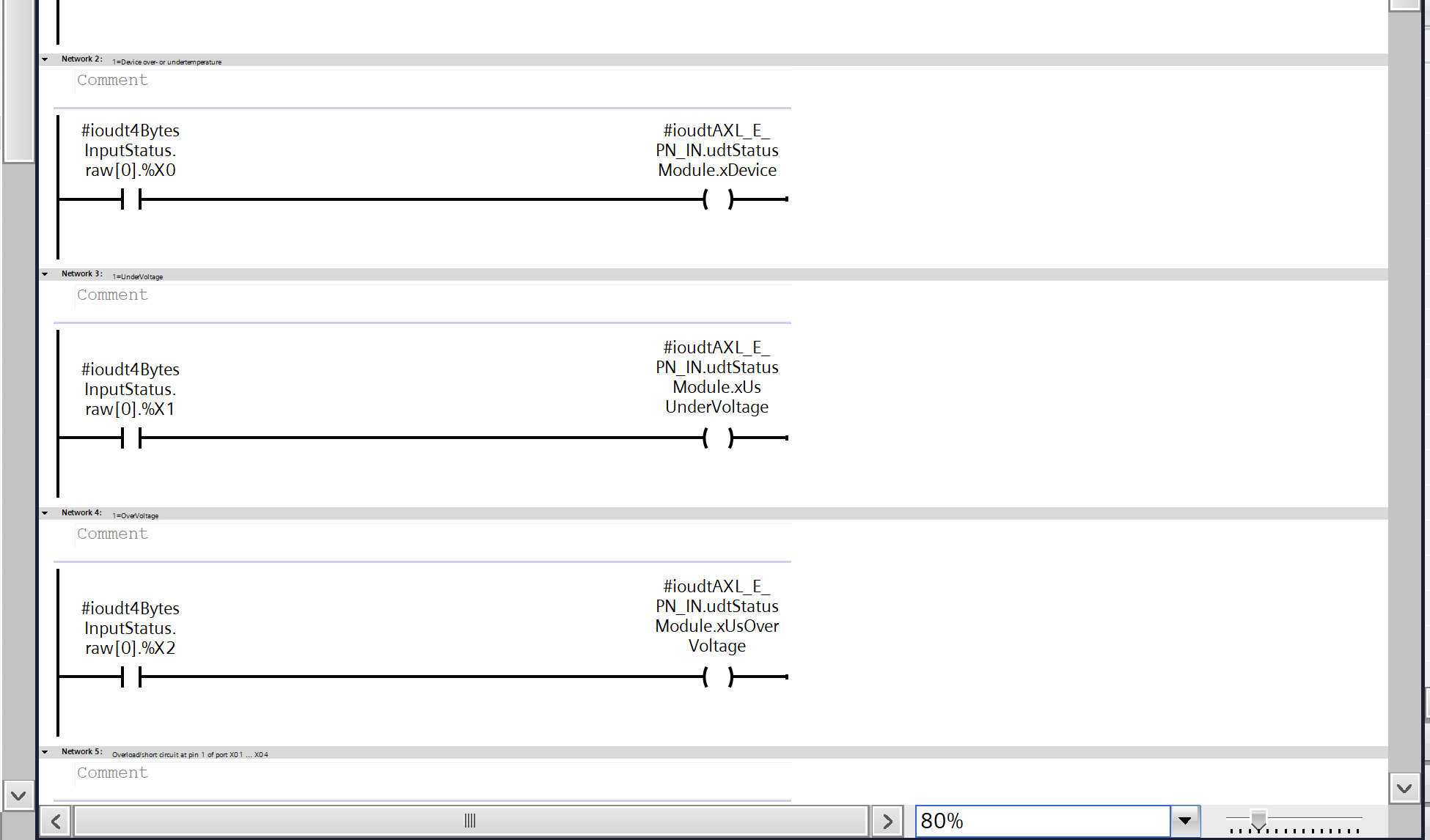
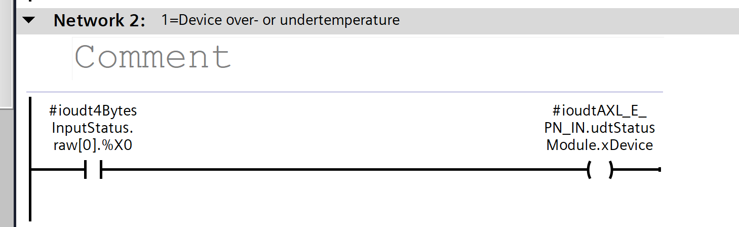
Network2
The first byte and first bit of the raw status data received via IO-Link (raw000.%X0) are converted into the device’s over-temperature/under-temperature fault flag.
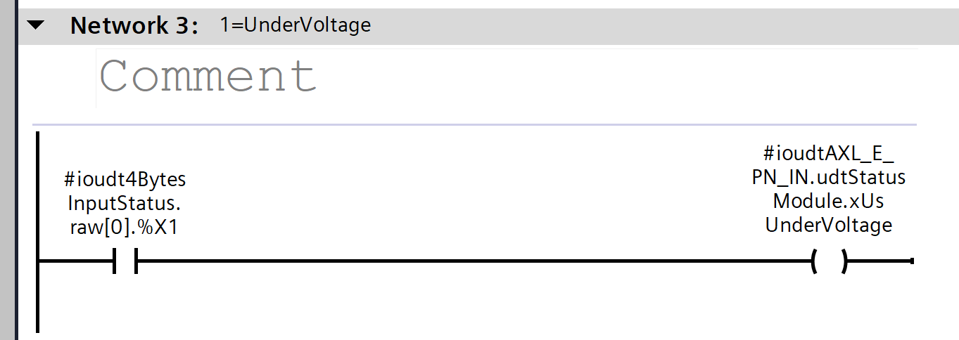
Network3
The first byte and first bit of the raw status data received from IO-Link (raw[0].%X1) are converted into a low-voltage (UnderVoltage) fault flag for the sensor power supply.
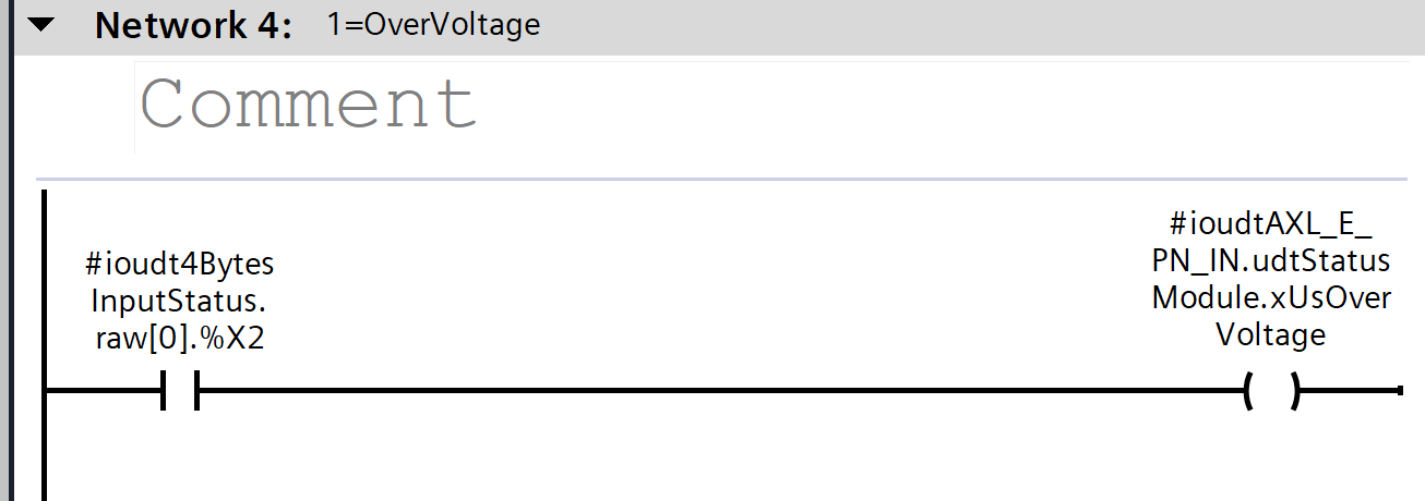
Network4
The 0th and 2nd bits of the raw status data received from IO-Link (raw[0].%X2) are converted into an overvoltage fault flag for the sensor power supply.
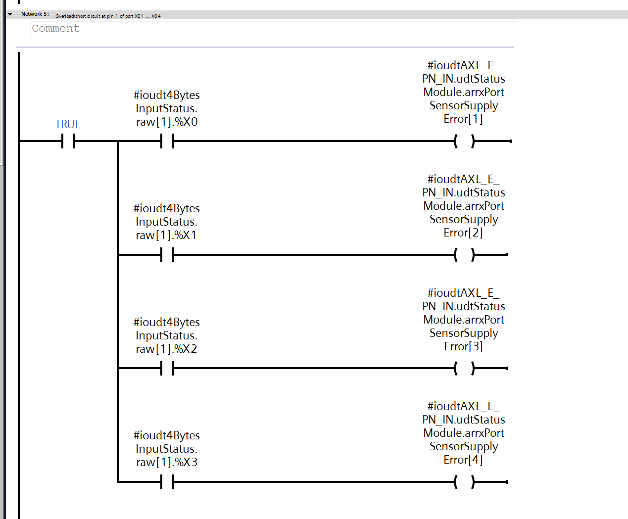
Network5
Each bit of the first byte of raw status data received via IO-Link (raw[1].%X0–%X3) is converted into the sensor power supply error flag (SensorSupplyError) for ports 1 through 4, respectively.
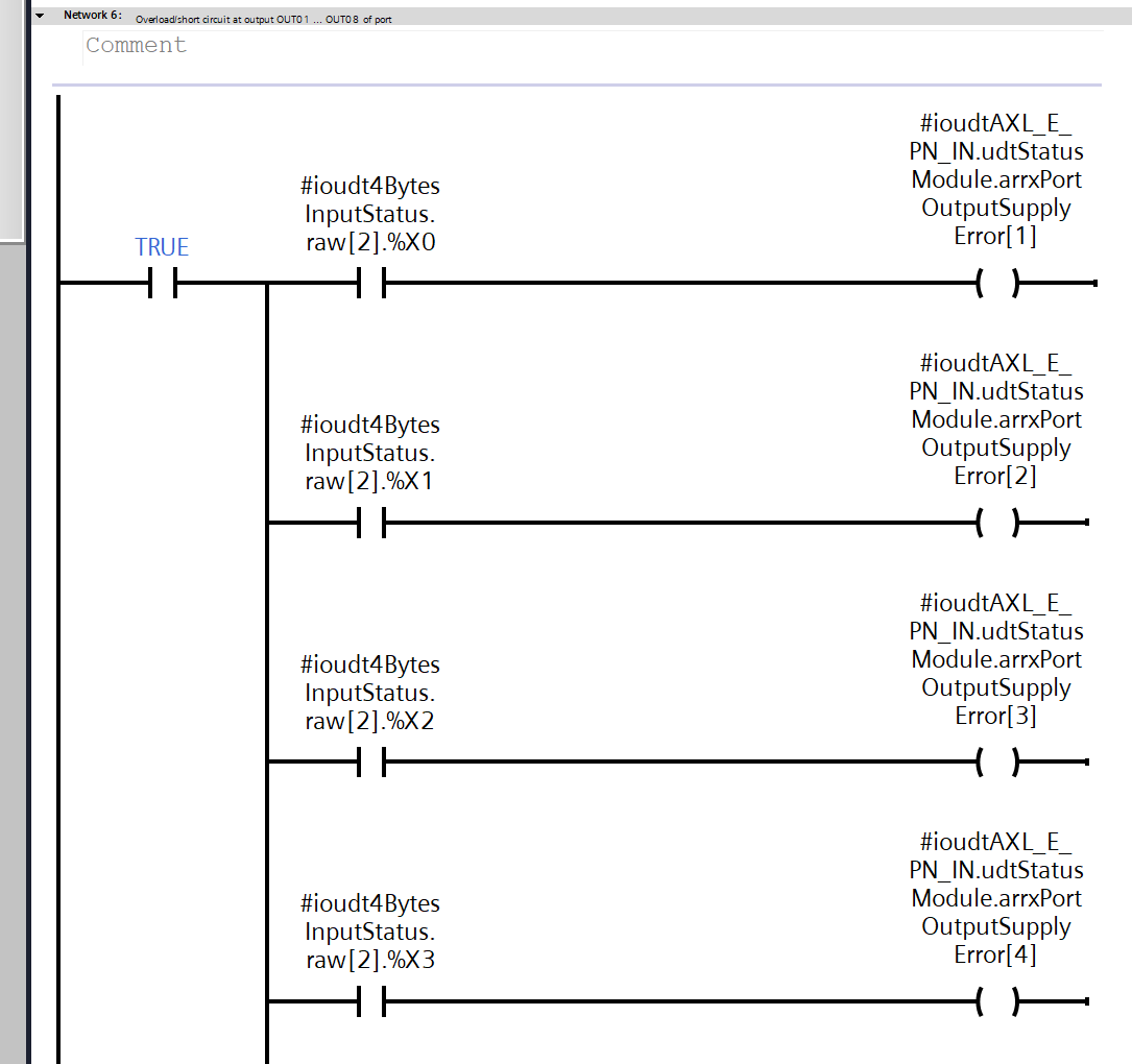
Network6
Each bit of the second byte of the raw status data received via IO-Link (raw[2].%X0–%X3) is converted into the output power supply error flag (OutputSupplyError) for ports 1–4.
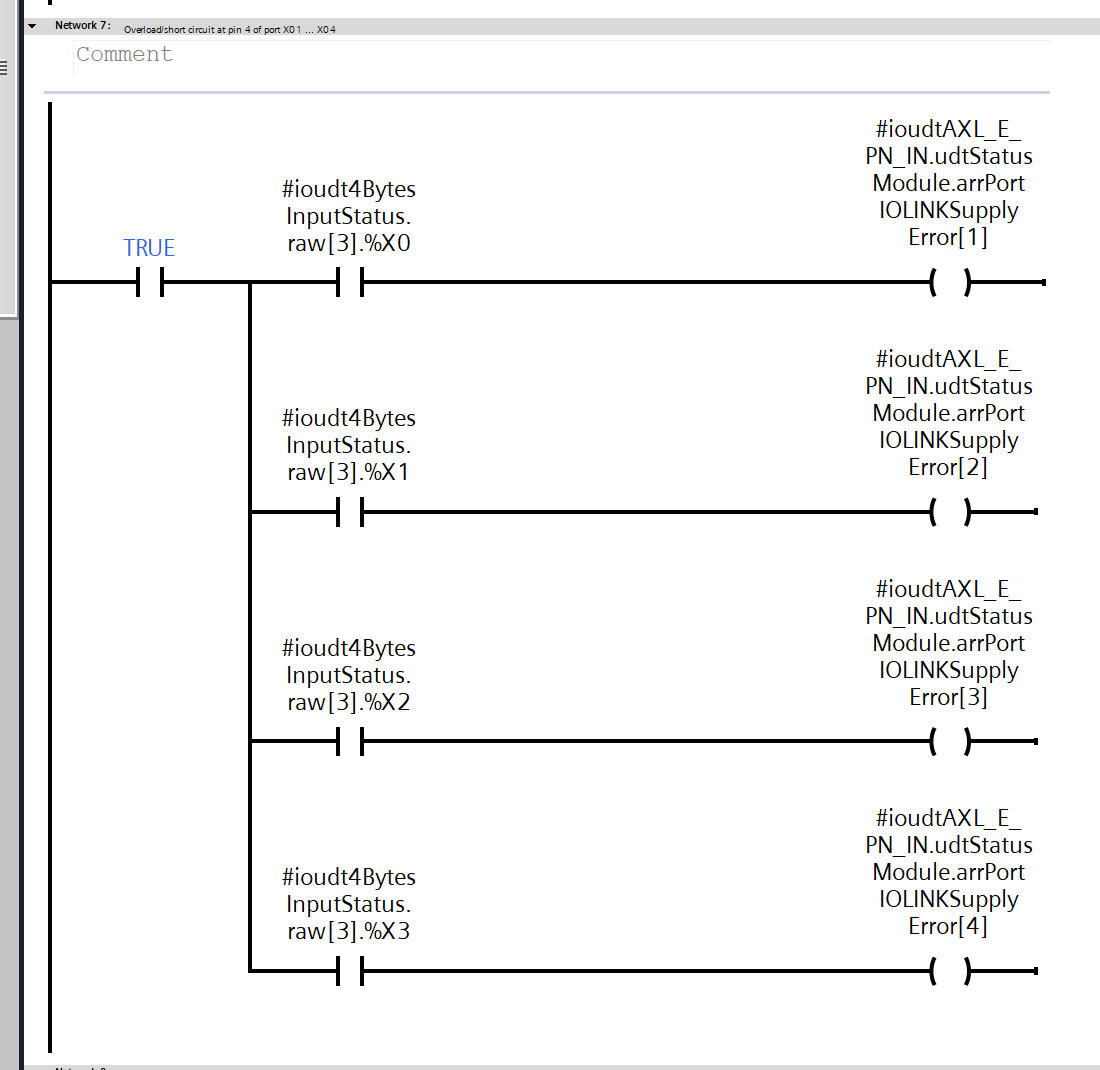
Network7
Each bit of the third byte of the raw status data received via IO-Link (raw[3].%X0–%X3) is converted into the IO-Link power supply error flag (IOLINKSupplyError) for ports 1–4.
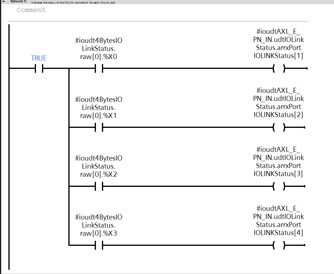
Network9
Each bit of the first byte of the raw link status data received via IO-Link (raw[0].%X0–%X3) is converted into the IO-Link connection status flag (IOLINKStatus) for ports 1 through 4, respectively.
Network10
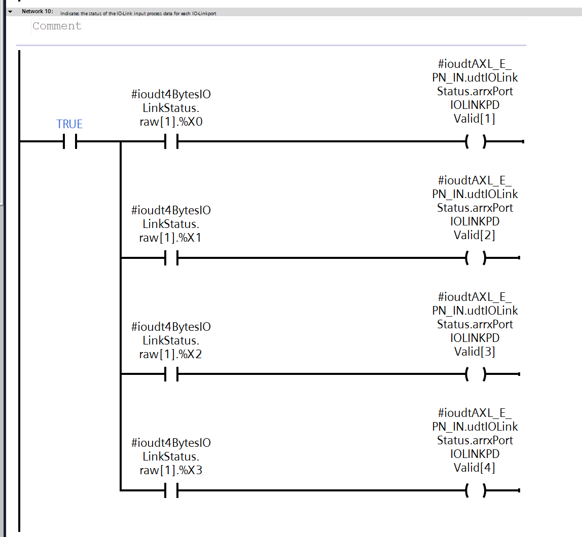
Each bit of the first byte of the raw link status data received via IO-Link (raw[1].%X0–%X3) is converted into the IO-Link process data valid flag (IOLINKPDValid) for ports 1 through 4, respectively.
Network11
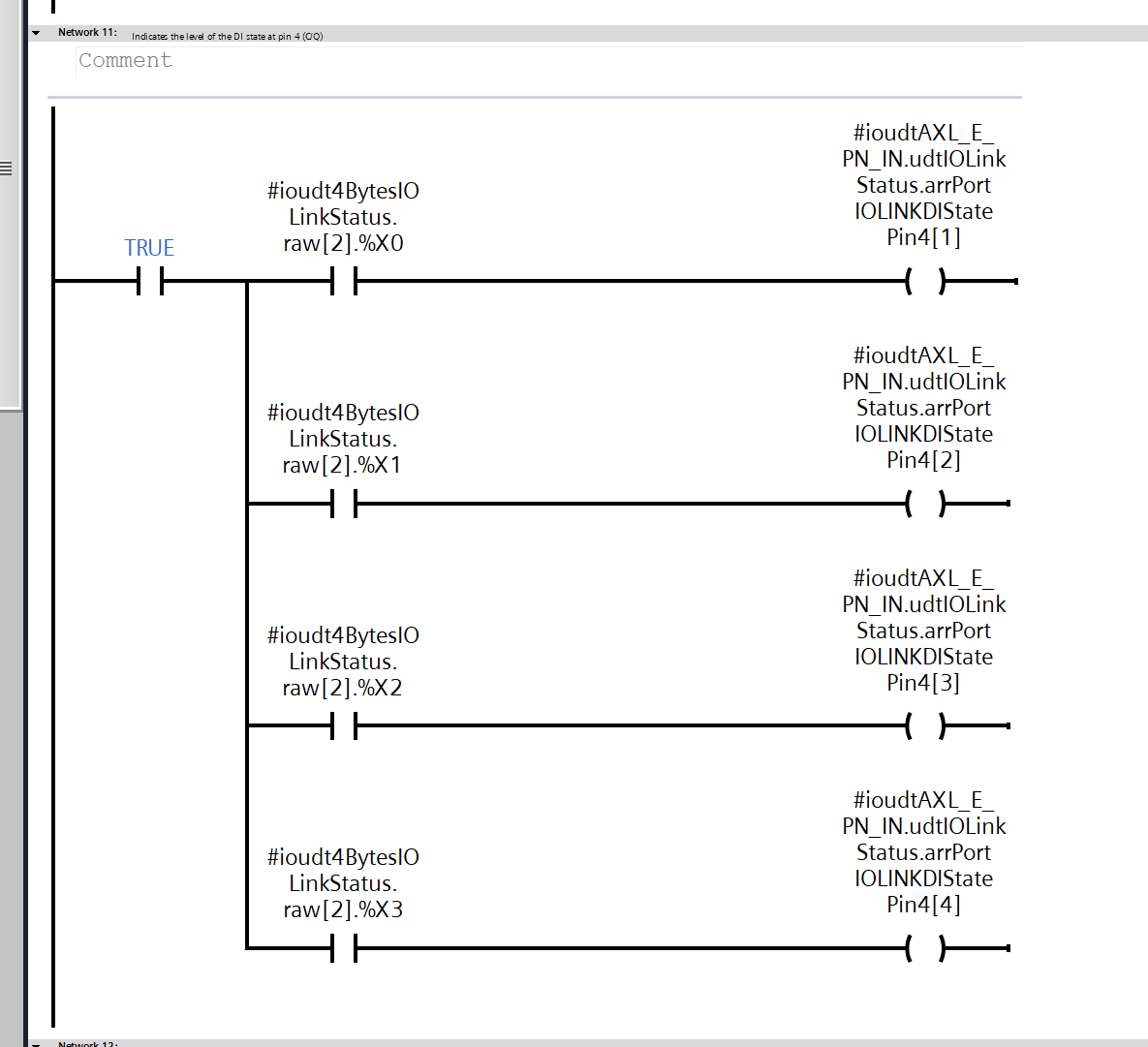
Each bit of the second byte of the raw link status data received via IO-Link (raw[2].%X0–%X3) is converted into the DI status flag (IOLINKDIStatePin4) for Pin 4 of each of ports 1 through 4.
OB1
Finally, we will create the OB1 program.
VAR
These are the variables defined in OB1.
Program
Next, we’ll create a ladder program.
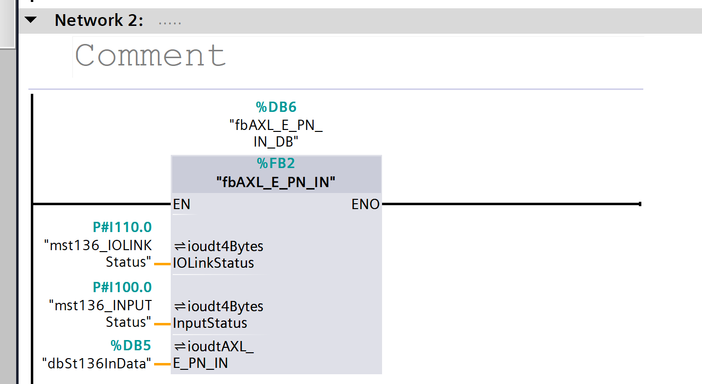
Network2
The raw IO-Link status data (IOLinkStatus) and raw input status data (InputStatus) obtained from the IO-Link master are passed to the FB, where they are converted and aggregated into the structured status (udtAXL_E_PN_IN) for the AXL E PN IN module.
Network3
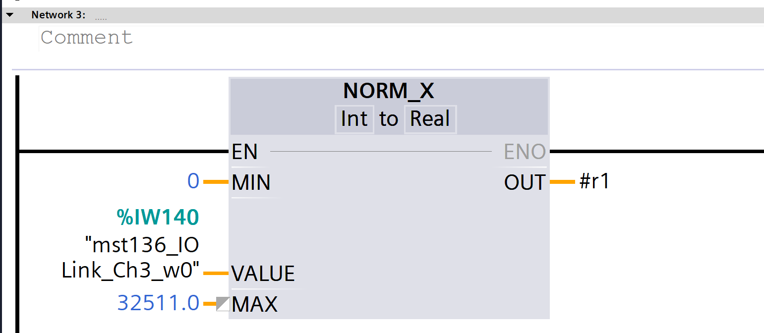
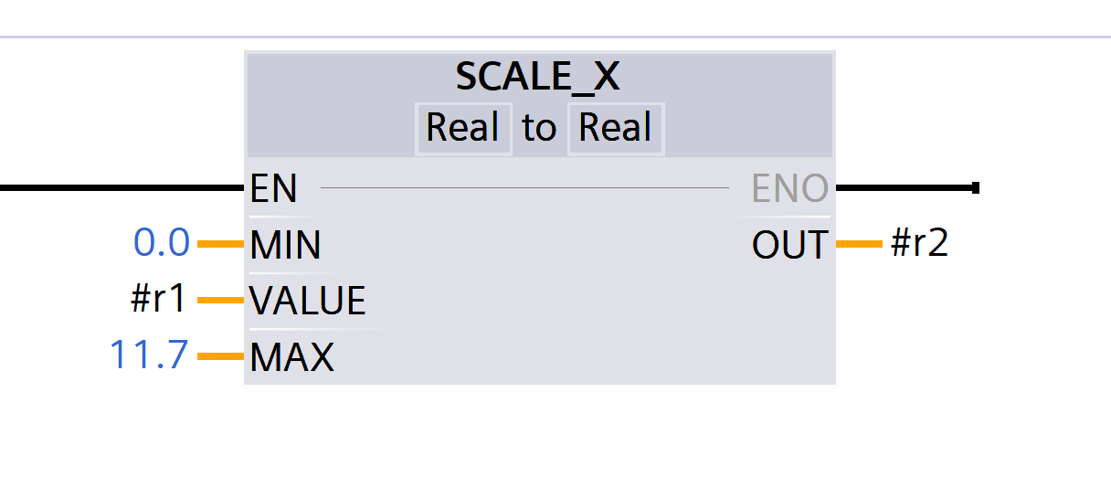
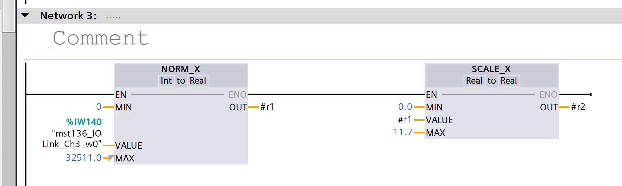
The raw analog value (Int) obtained from the Murrelektronik 5000-00501-1300001 analog-to-IOLINK converter is normalized to a range of 0 to 1 using NORM_X, and the result is then converted to a real-scale value ranging from 0.0 to 11.7 using SCALE_X.
Network4
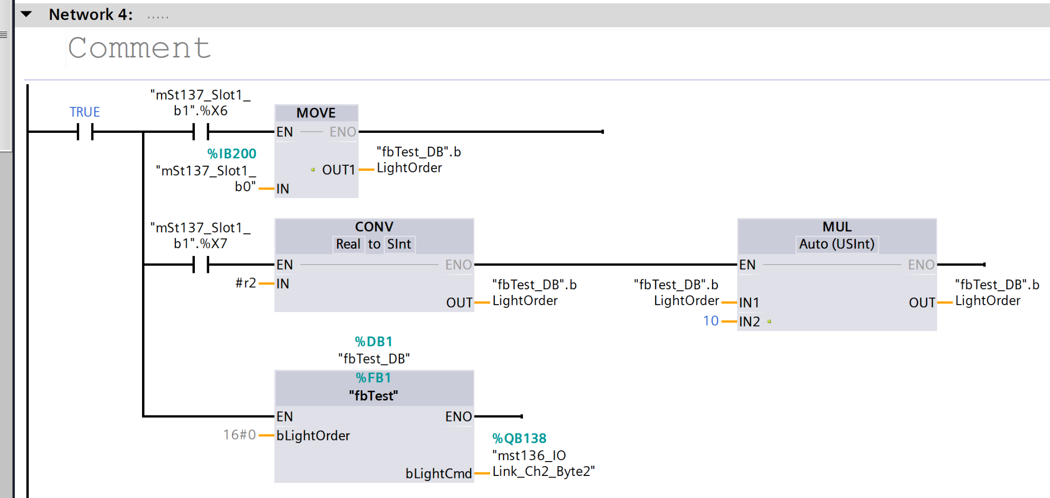
The system converts the number of lit segments (LightOrder) based on the state of the input bits, multiplies that value by 10, and uses it to calculate the illumination level command value (byte data) for IO-Link.
Network5
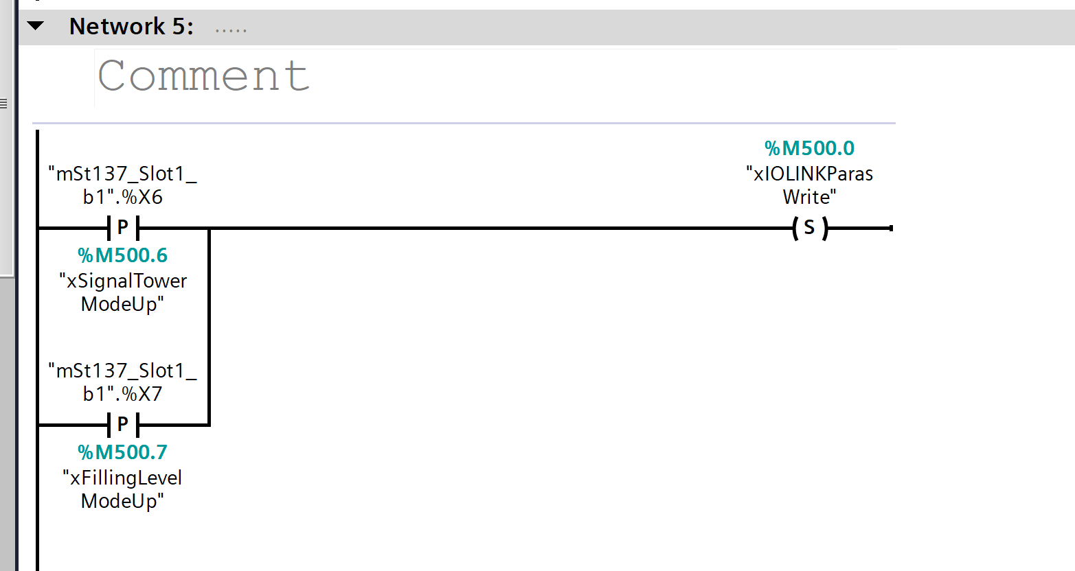
The system detects the input (b1.%X6/b1.%X7) used to switch between Signal Tower mode and Fill Level mode, and sets the IO-Link parameter write request flag (xIOLINKParasWrite).
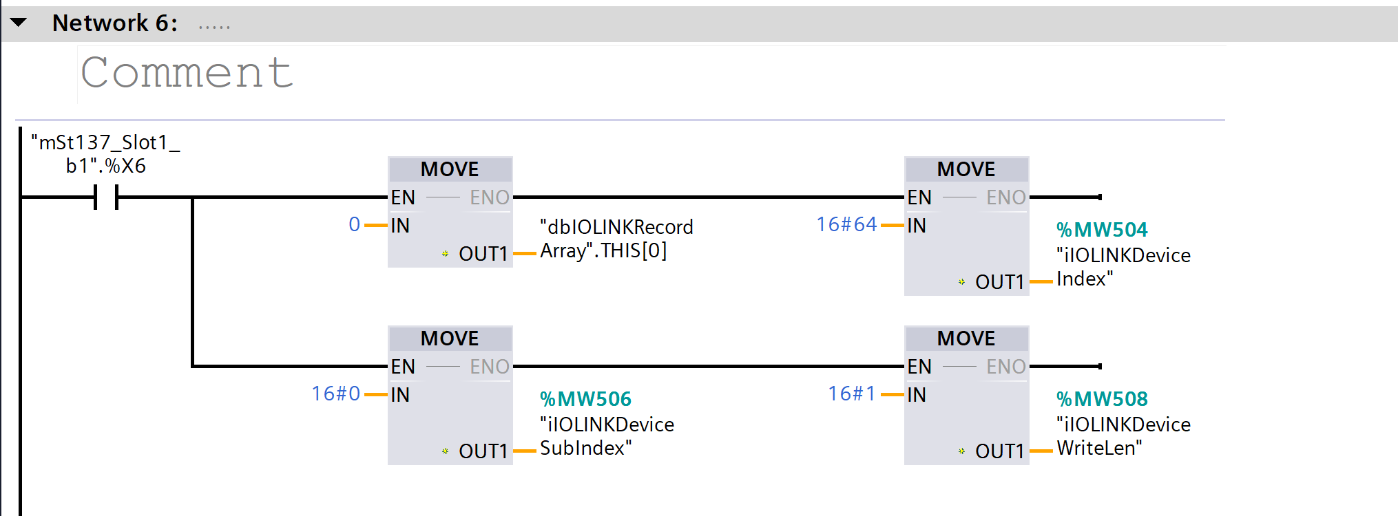
Network6
When the mode switch bit (b1.%X6) is ON,
the “Index, SubIndex, WriteLen, and Record value (16#64)” are set for writing IO-Link parameters.
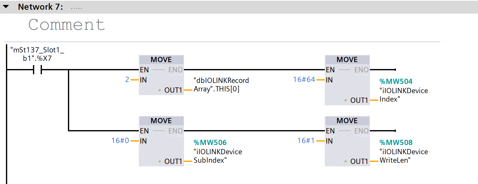
Network7
When the mode switch bit (b1.%X7) is ON,
the “Index, SubIndex, WriteLen, and Record value (16#64)” are set for writing IO-Link parameters.
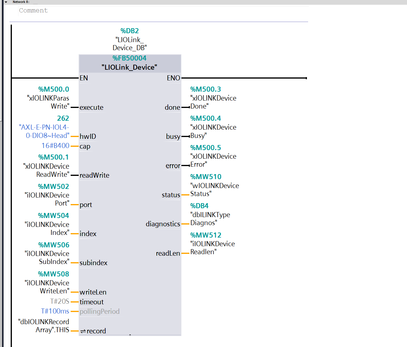
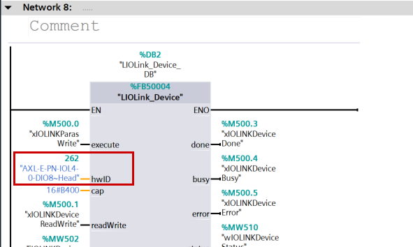
Network8
Using the specified Index, SubIndex, and data, the IO-Link_Device FB is executed to read and write parameters to the IO-Link device and retrieve the results (completed, busy, error, or status).
How to Use LIOLink
Just to clarify, using the LIOLink library is the same as performing standard Facebook operations.
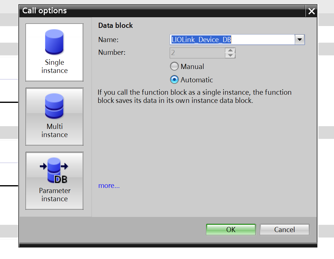
Specify the instance type.
Cap input variable
The “cap” parameter is hidden under “Default”; please click the arrow button at the bottom of the “Block” section.
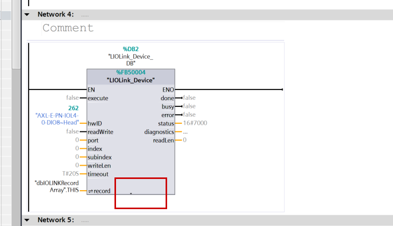
The cap parameter is displayed.
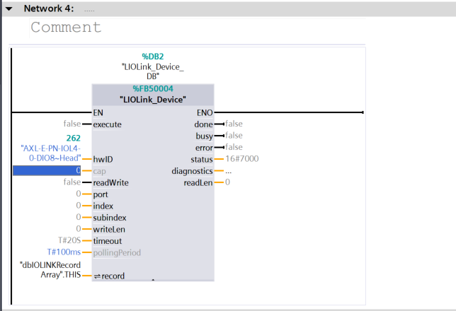
Please enter 16#B400 there.

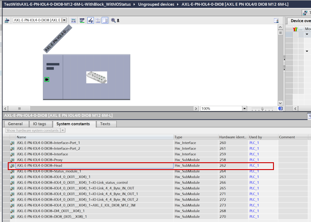
hwID
To use the LIOLink_Device library, another required parameter is the hwID.
Switch to Device View for AXL E IOL DIO8 M12 3M → open Properties → System constants, then select “AXL-E-PN-IOL4-0-DIO8~Head” from the list.
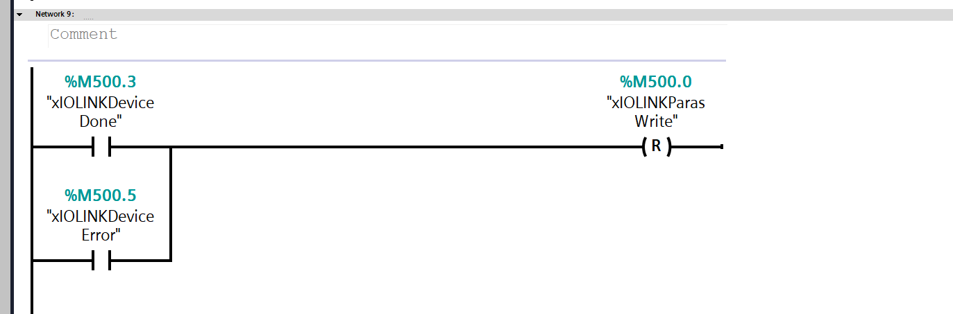
Network9
When IO-Link communication is marked as “Done” or “Error,” the parameter write request flag (xIOLINKParasWrite) is reset.
Download
Finally, let’s download the project to the S7-1500.
Results
Done!The Profinet communication was established without errors.
You can see it in action in this video.