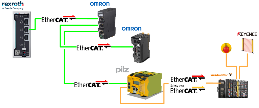
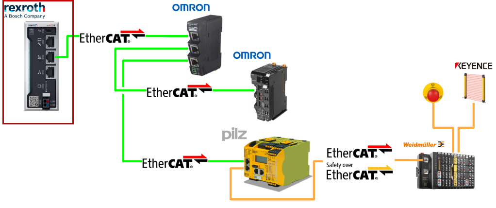
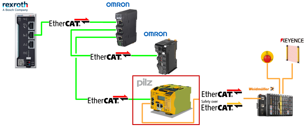
In this article, we will set up an EtherCAT network using ctrlX and the EtherCAT app, and also build an FSoE network in cooperation with Pilz’s PNOZ m EF EtherCAT FSoE. The FSoE Slave devices used are from Weidmuller.
Let’s enjoy Factory Automation (FA).
Reference Link
Reference Video
Implementation
Download ESI File
First, download the ESI files for each EtherCAT Slave.
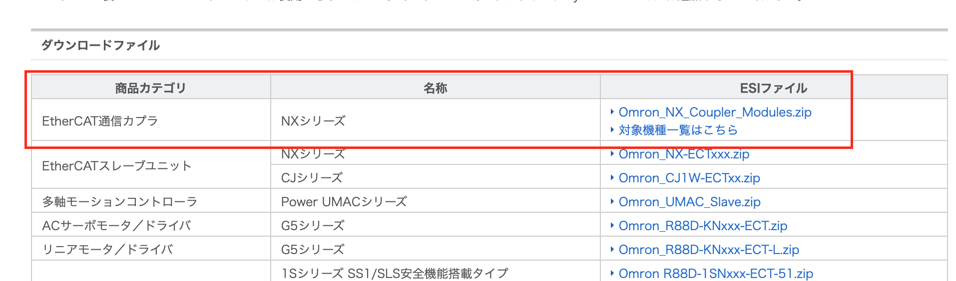
OMRON NX EtherCAT Coupler
Please download the OMRON NX EtherCAT Coupler ESI File from this link.
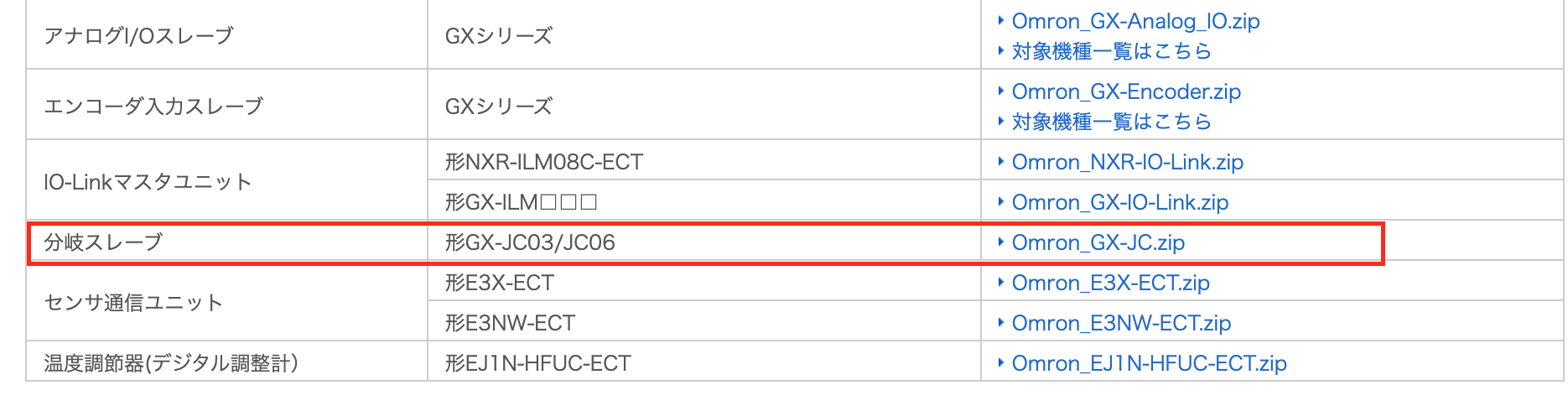
OMRON GX-JC03/JC06 Junction Coupler
Please download the OMRON GX-JC03/JC06 Junction Coupler ESI File from this link.
https://www.fa.omron.co.jp/member/product/tool/23/esi/download.htm
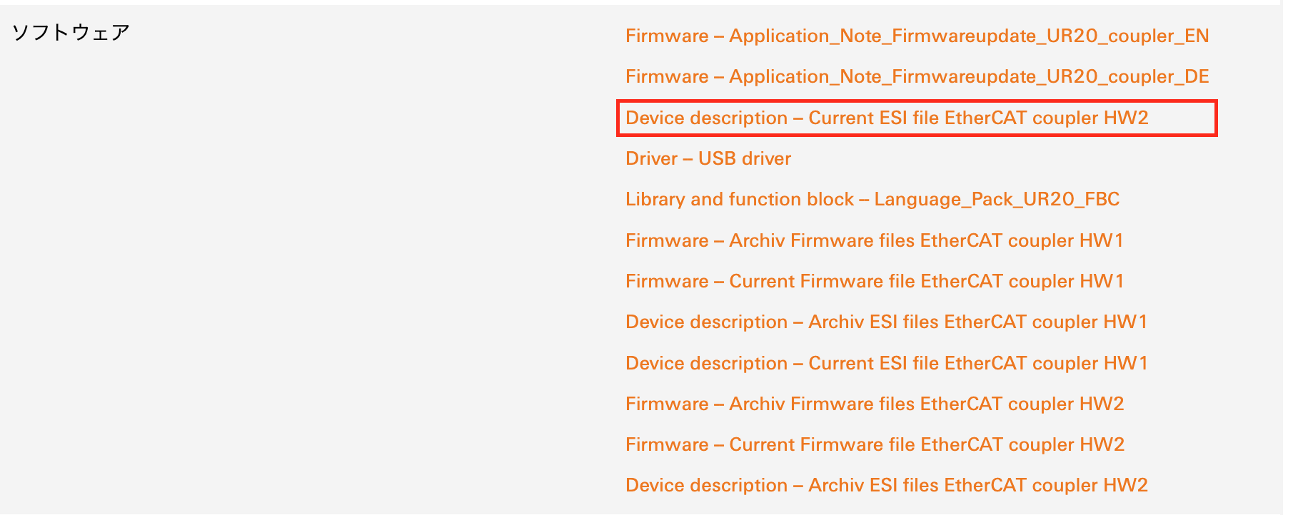
Weidmuller EtherCAT Coupler
Please download the Weidmuller EtherCAT Coupler ESI File from this link.
https://eshop.weidmueller.com/ja/ur20-fbc-ec/p/1334910000
Pilz PNOZ m EF EtherCAT FSoE
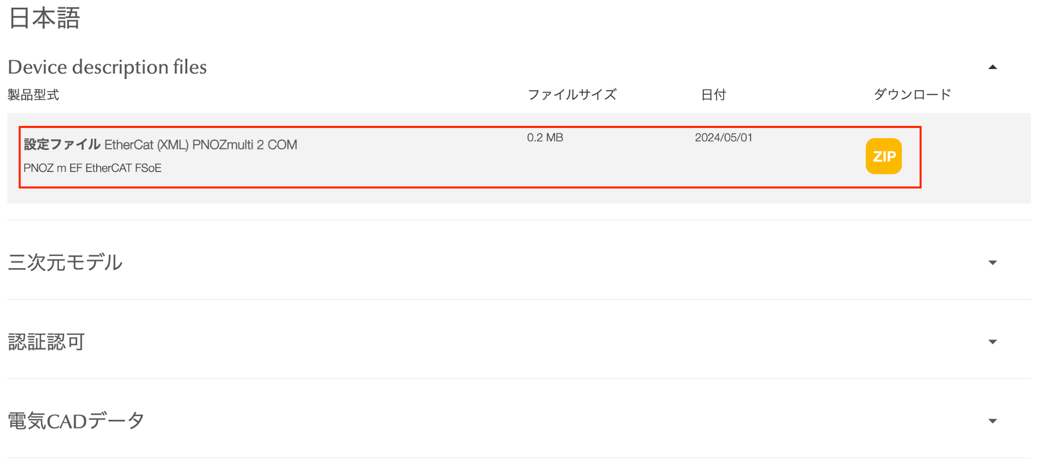
Please download the Pilz PNOZ m EF EtherCAT FSoE ESI File from this link.
Wiring
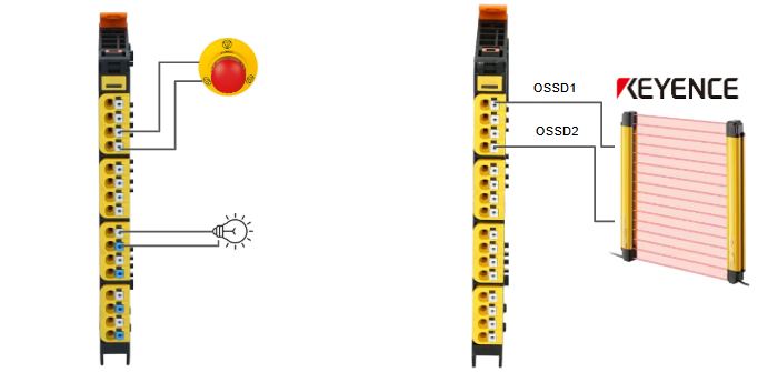
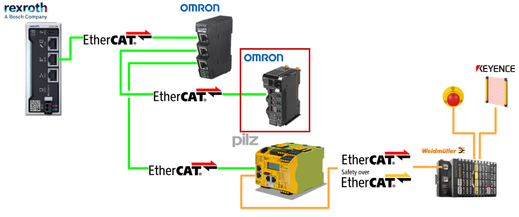
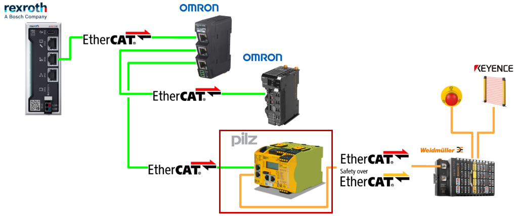
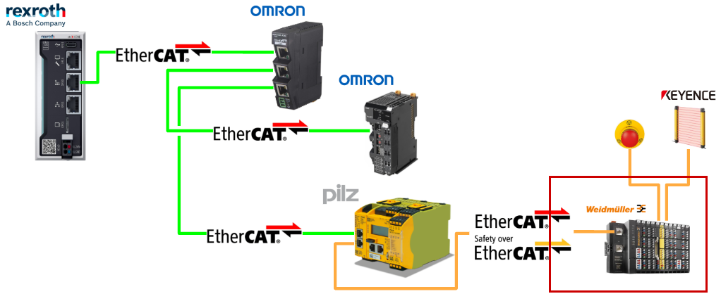
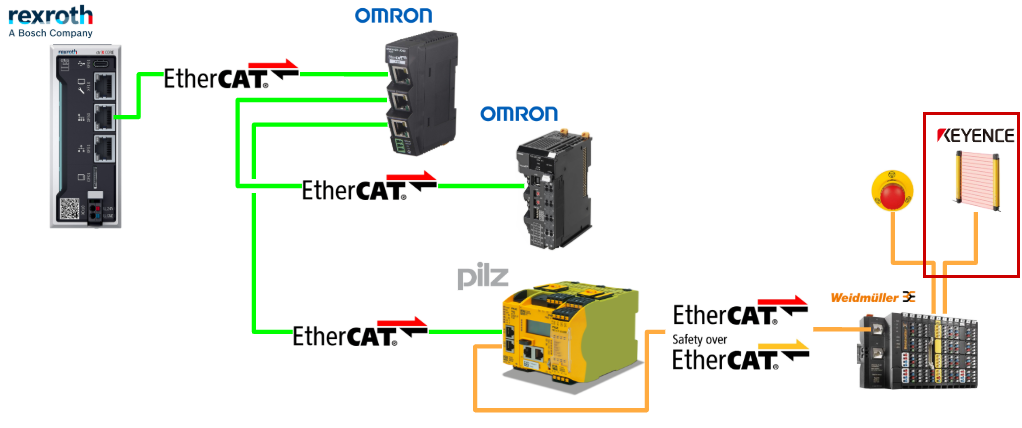
Here is the wiring diagram for the Weidmuller FSoE Slave used in this article.
Ctrlx Side
First, we will configure the ctrlX side.
EtherCAT Master
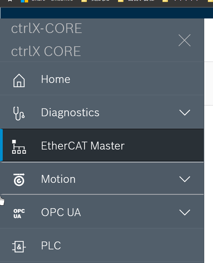
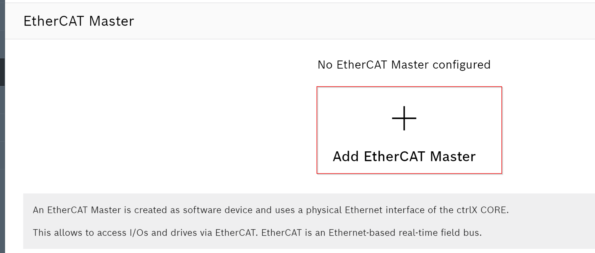
Since we will build the EtherCAT network from the EtherCAT Master Apps, access the ctrlX PLC Web Server and click on EtherCAT Master.
Click Add EtherCAT Master to add an EtherCAT Master.
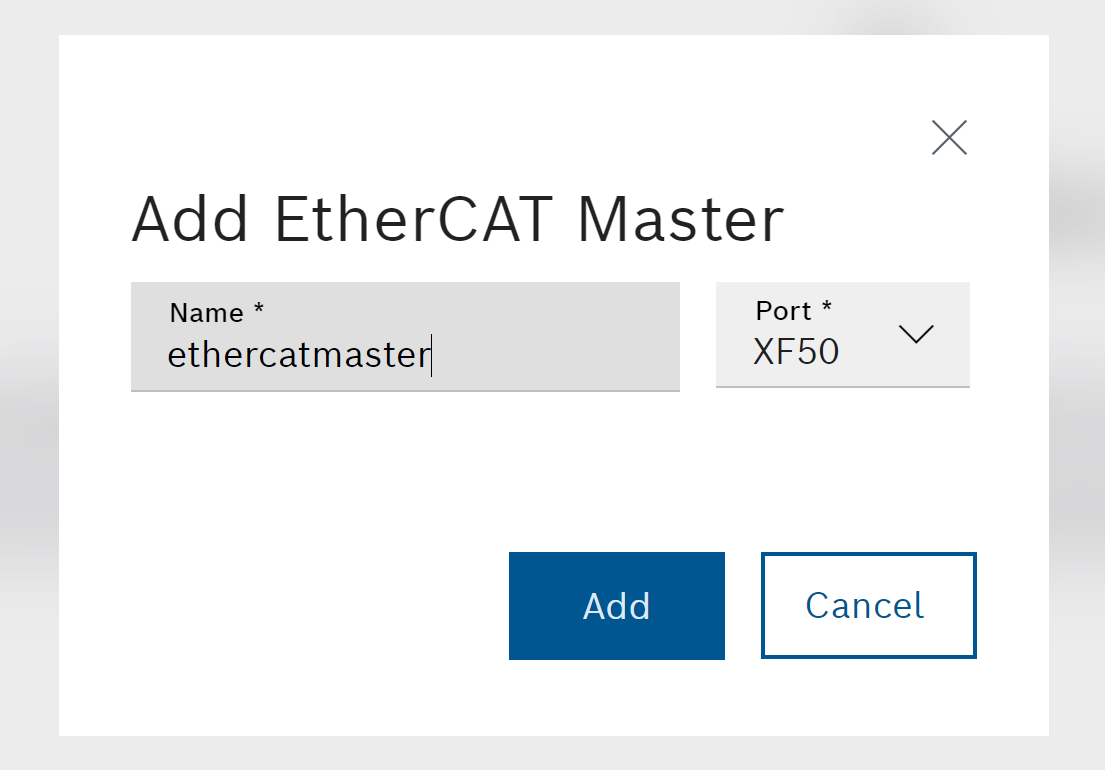
Set the EtherCAT Master name and the Port to use.
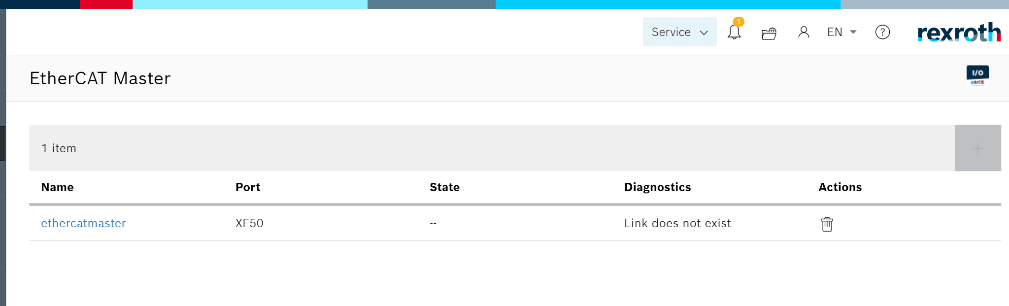
Done! The EtherCAT Master has been added.
Configure EtherCAT
To configure the EtherCAT network, you need to use ctrlX IO Engineering.
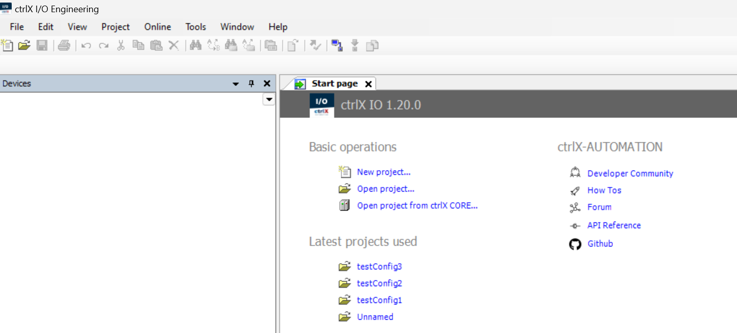
This is the initial screen of ctrlX IO Engineering.
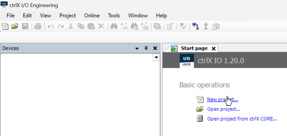
New Project
Click New Project to create a new project.
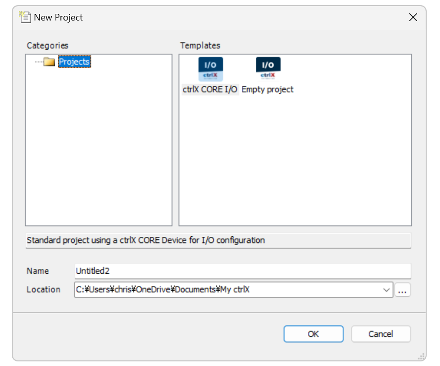
Select ctrlX CORE I/O > Create Project.
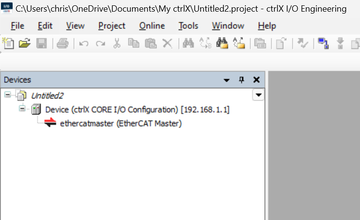
Done! A new project has been created.
Install ESI File
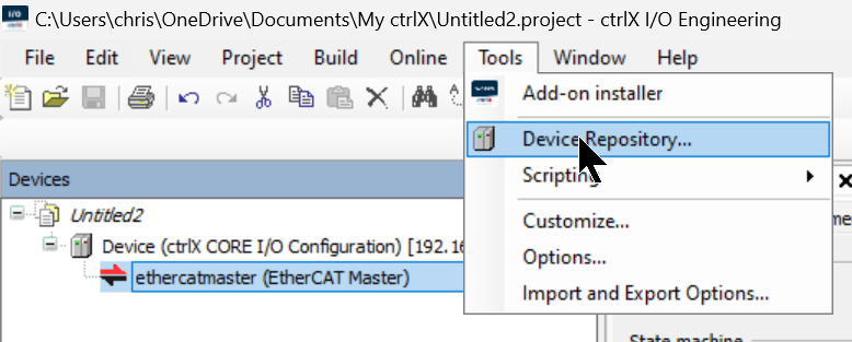
Import the ESI Files downloaded from the manufacturer’s website earlier via Tools > Device Repository.
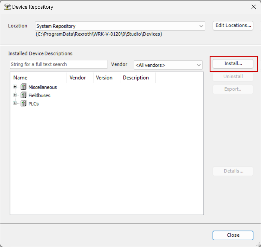
Click the Install button to import the ESI File.
Configure EtherCAT Slave
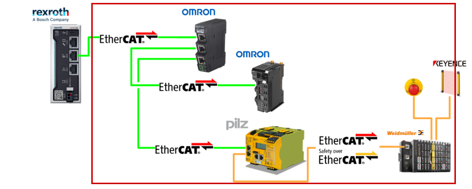
Now let’s configure the EtherCAT network in ctrlX.
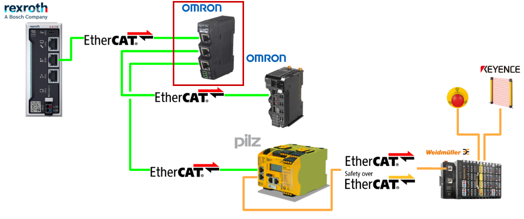
Add OMRON junction
Of course, you can search for EtherCAT Slaves using the ctrlX Scan function, but this time, let’s add the Slaves one by one manually.
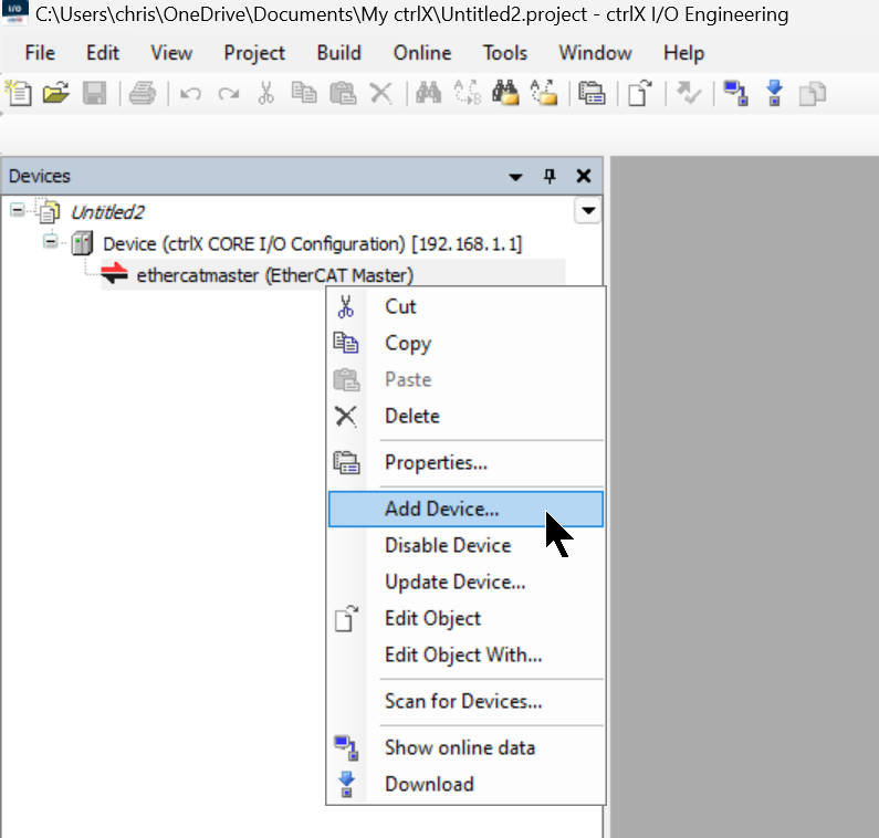
Right-click on ethercatmaster > Add Device.
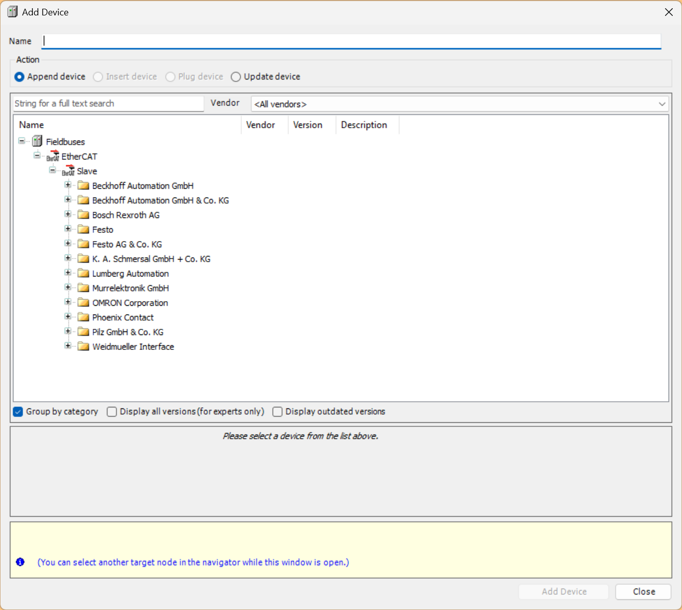
This is the EtherCAT Slave addition screen.
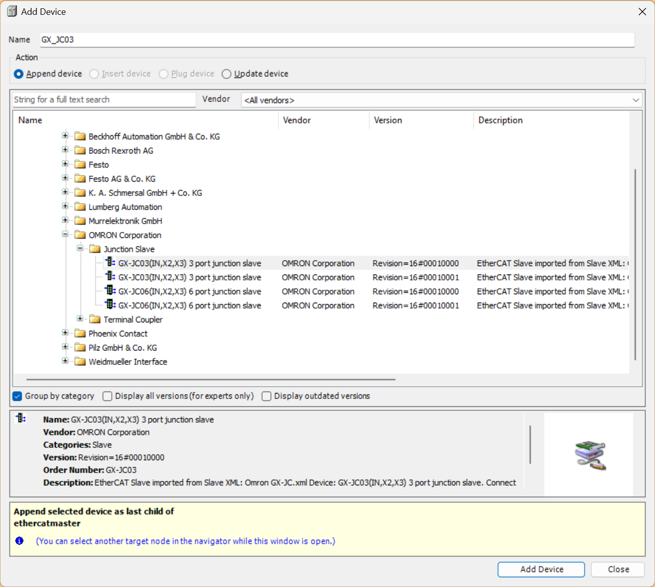
Select OMRON > Junction Slave > GX-JC03 > Add Device to add it.
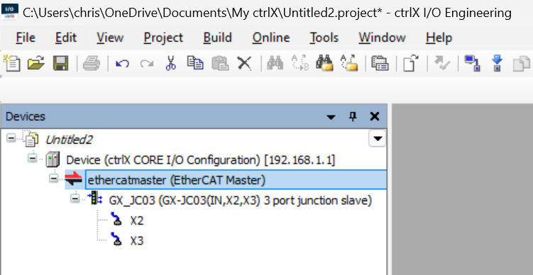
Done! OMRON’s GX-JC03 has been added to the EtherCAT network.
Add OMRON Coupler
Next, let’s add the OMRON NX-ECC203 EtherCAT Coupler.
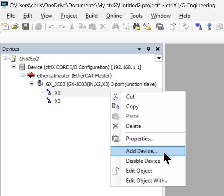
Since the OMRON EtherCAT Coupler NX-ECC203 is connected to the X2 port of the GX-JC03, right-click on X2 > Add Device.
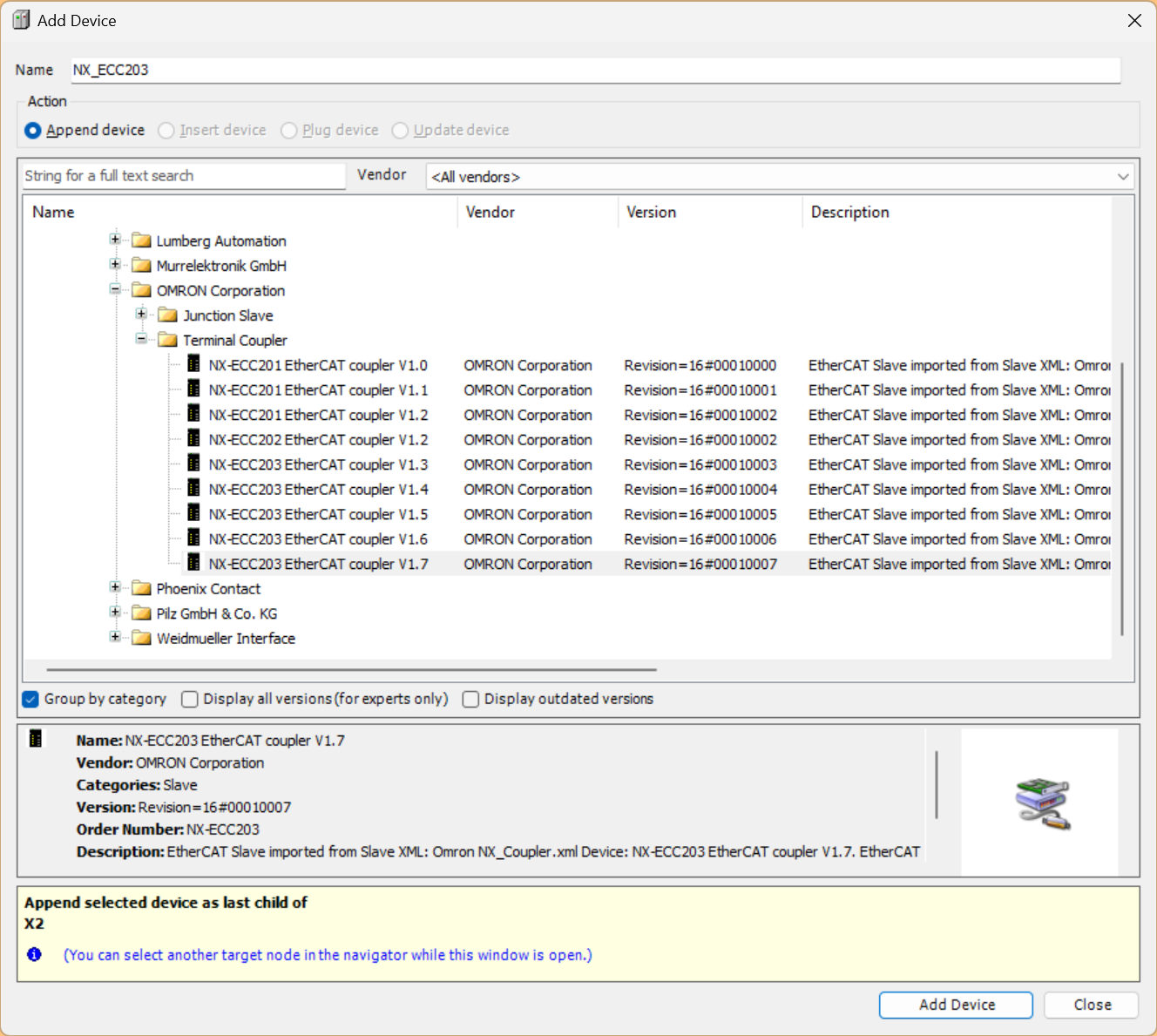
Select OMRON > Terminal Coupler > NX-ECC203 EtherCAT Coupler > Add Device to add it to the EtherCAT network.
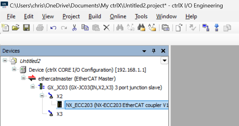
Done! OMRON’s NX-ECC203 has been added.
Add NX-ID5442
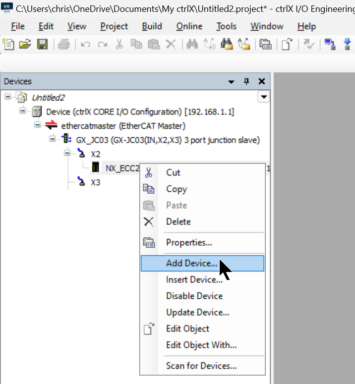
Since the 16-point PNP input module NX-ID5442 is installed in Slot1 of the NX-ECC203, right-click on NX-ECC203 > Add Device.
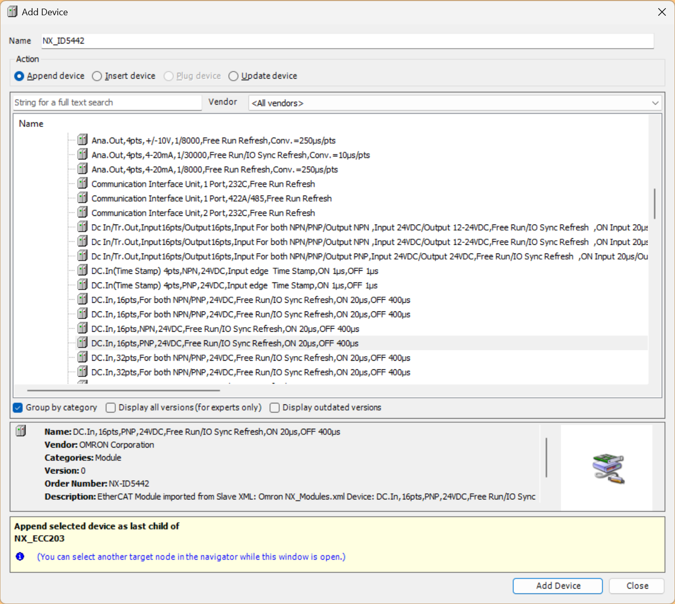
Select NX-ID5442 > Add Device to add the module.
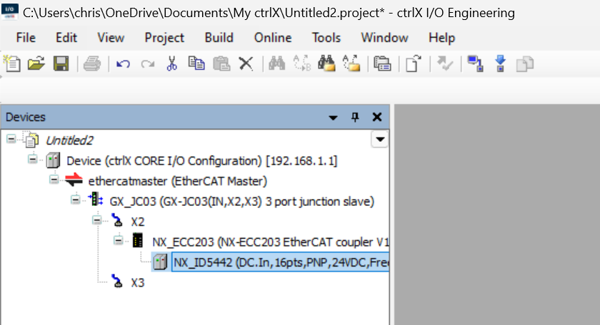
Done!
Add NX-OD5256
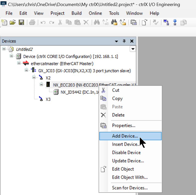
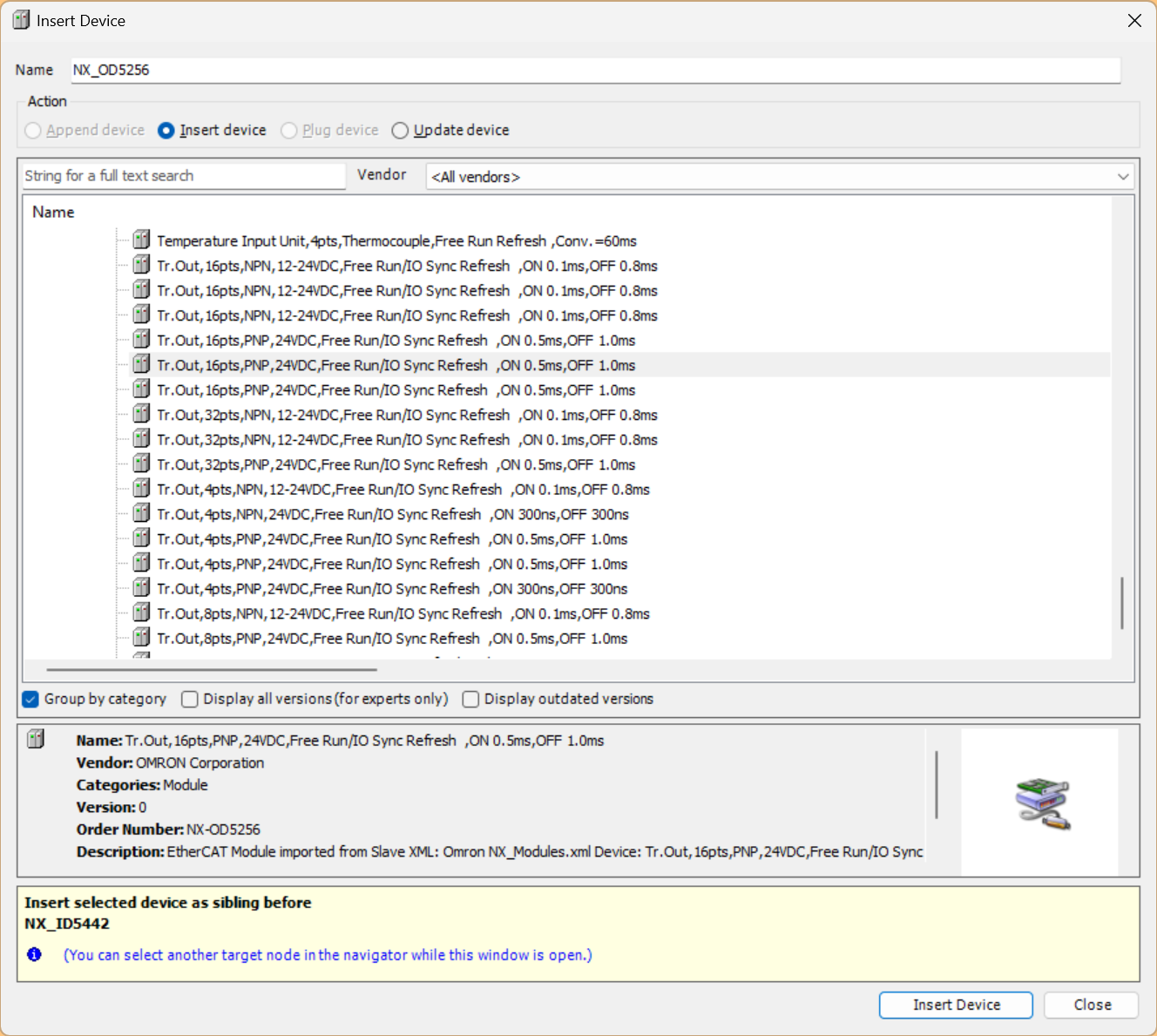
Since the 16-point output module NX-OD5256 is installed in Slot2 of the NX-ECC203, right-click on NX-ECC203 > Add Device.
Select NX-OD5256 > Add Device to add the module.
Done!
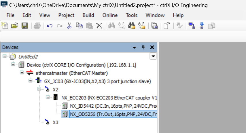
Add ILM400
Since the IO-Link module NX-ILM400 is installed in Slot3 of the NX-ECC203, right-click on NX-ECC203 > Add Device.
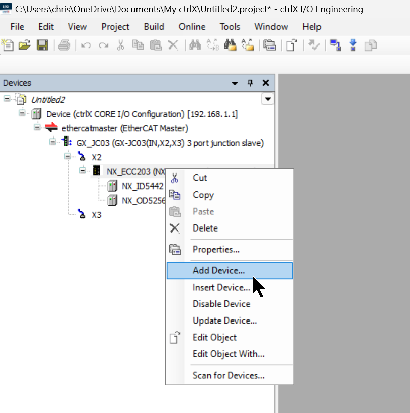
Select NX-ILM400 > Add Device to add the module.
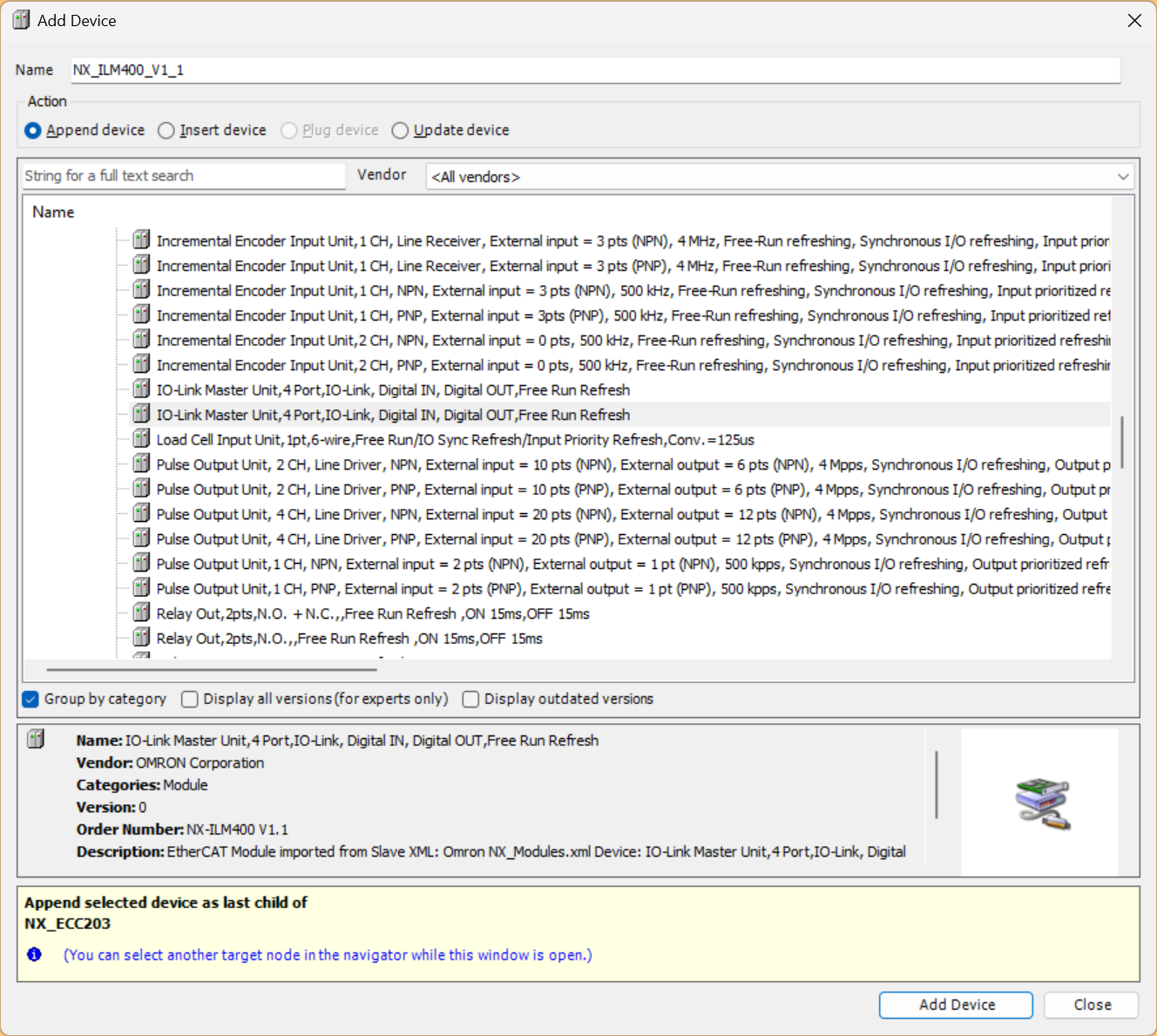
Done!
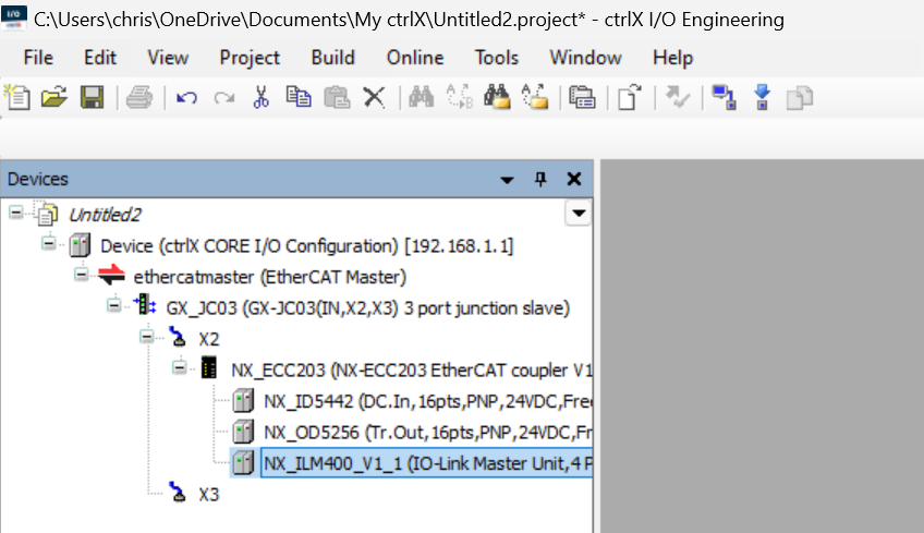
Result
This completes the configuration of the OMRON EtherCAT Coupler NX-ECC203.
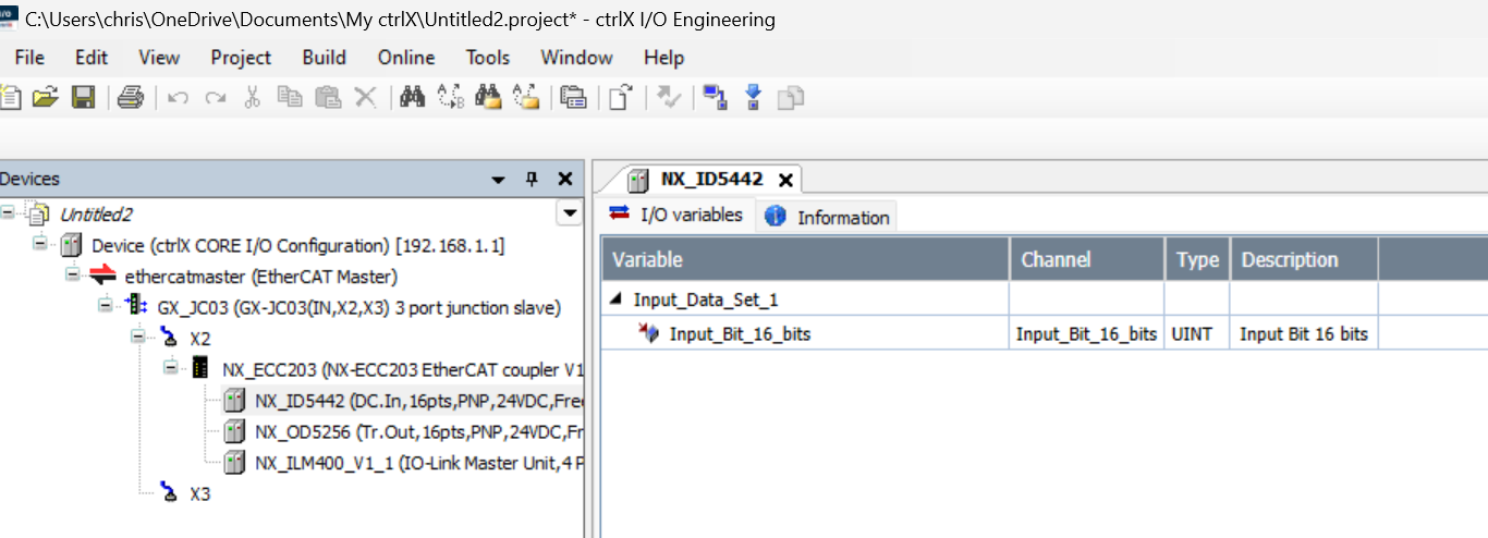
Add PNOZ m EF EtherCAT FSoE
Next, let’s add the Pilz PNOZ m EF EtherCAT FSoE, which is connected to the X3 port of the OMRON EtherCAT junction.
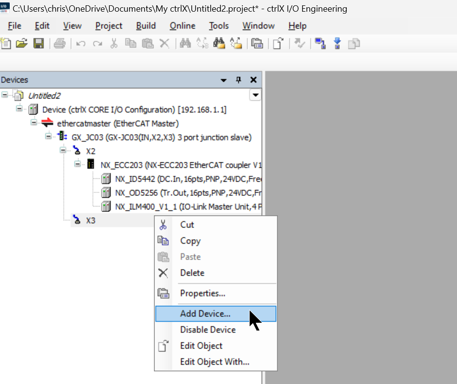
Right-click on X3 of the OMRON GX-JC03 Junction Box > Add Device.
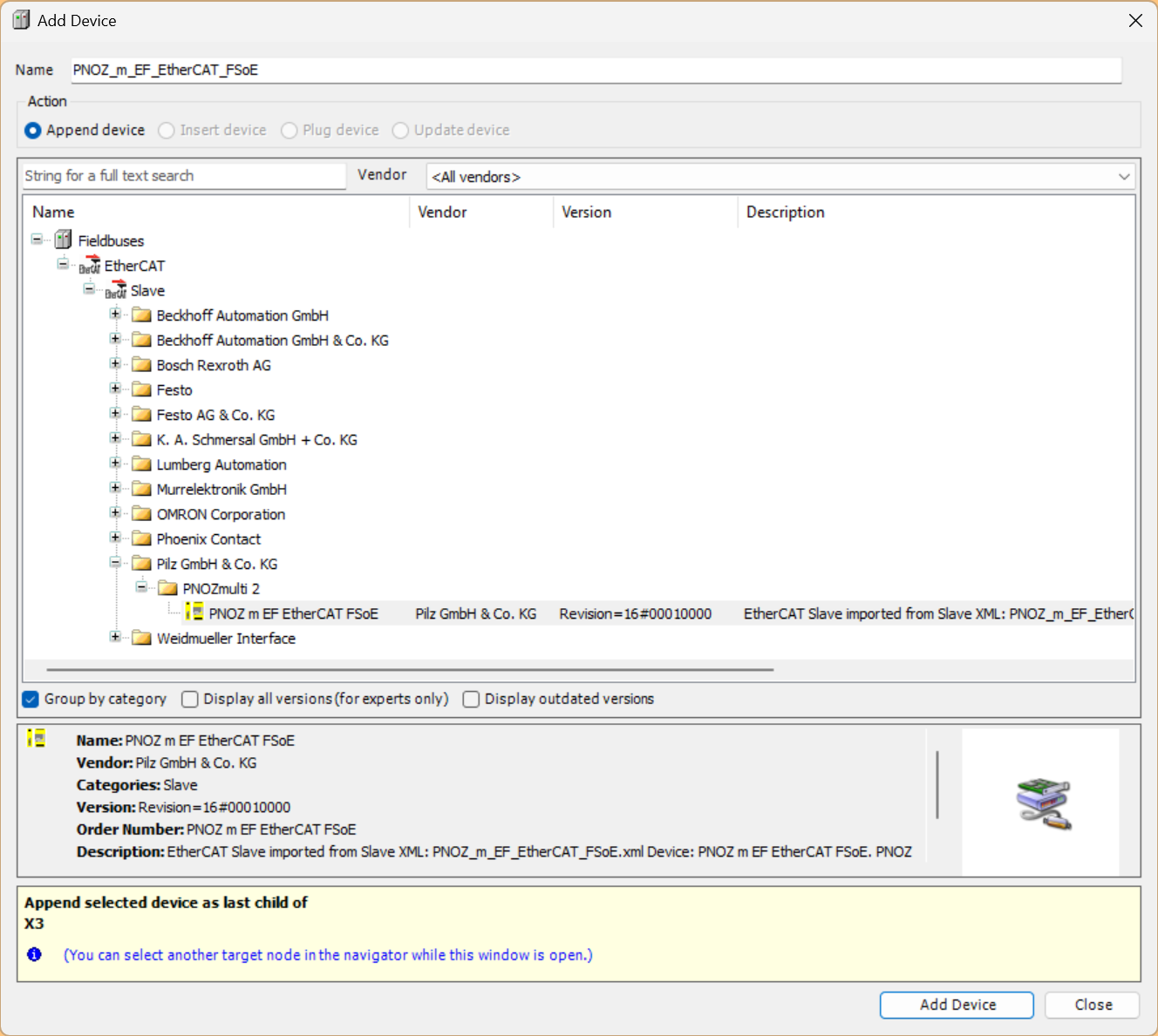
Select Pilz > PNOZmulit 2 > PNOZ m EF EtherCAT FSoE, and click Add Device to add the device.
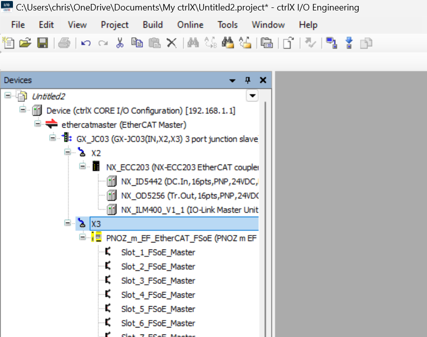
Done! The Pilz PNOZ m EF EtherCAT FSoE module has been added to X3.
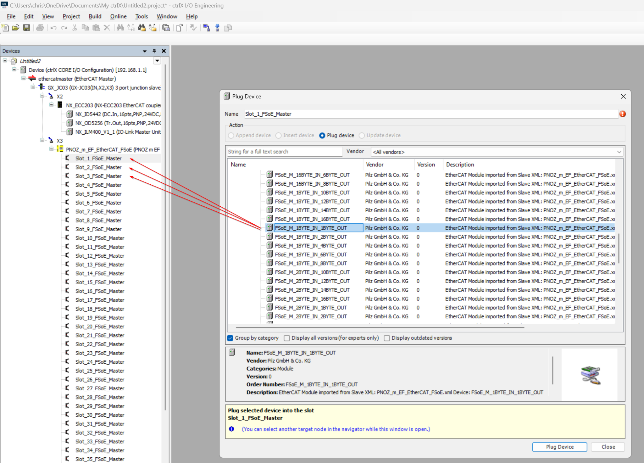
Add FSoE 1 Byte IN 1 Byte Out
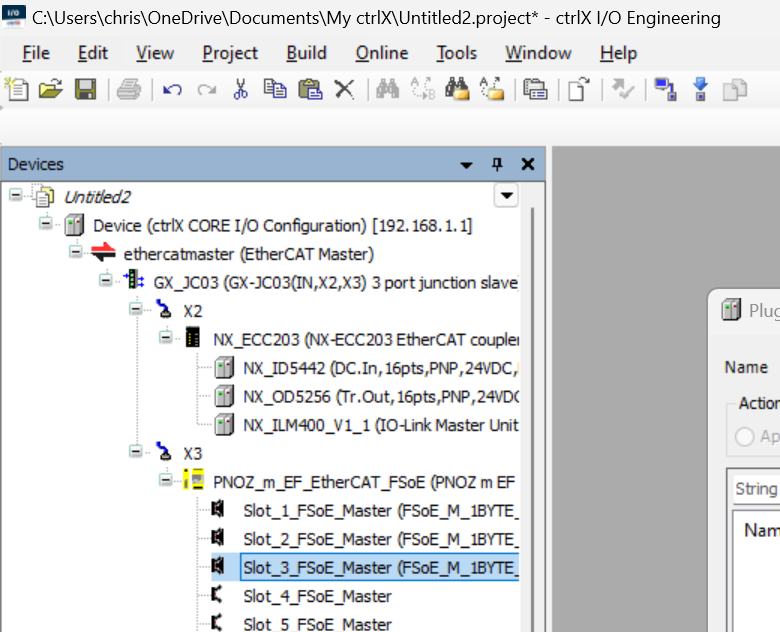
Since we will use three Weidmuller FSoE Slaves in this article, please add FSoE_M_1BYTE_IN_1BYTE_OUT to Slot1/Slot2/Slot3.
Done!
Add Weidmuller EtherCATCoupler
Next, we will add the Weidmuller EtherCAT Coupler.
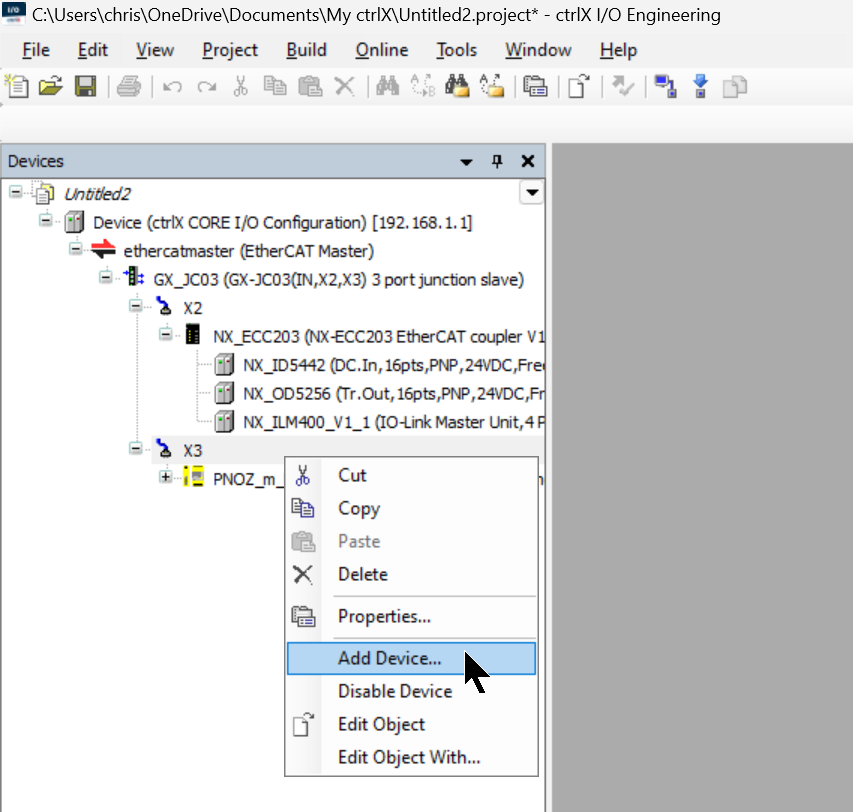
Right-click on X3 of the OMRON GX-JC03 Junction Box > Add Device.
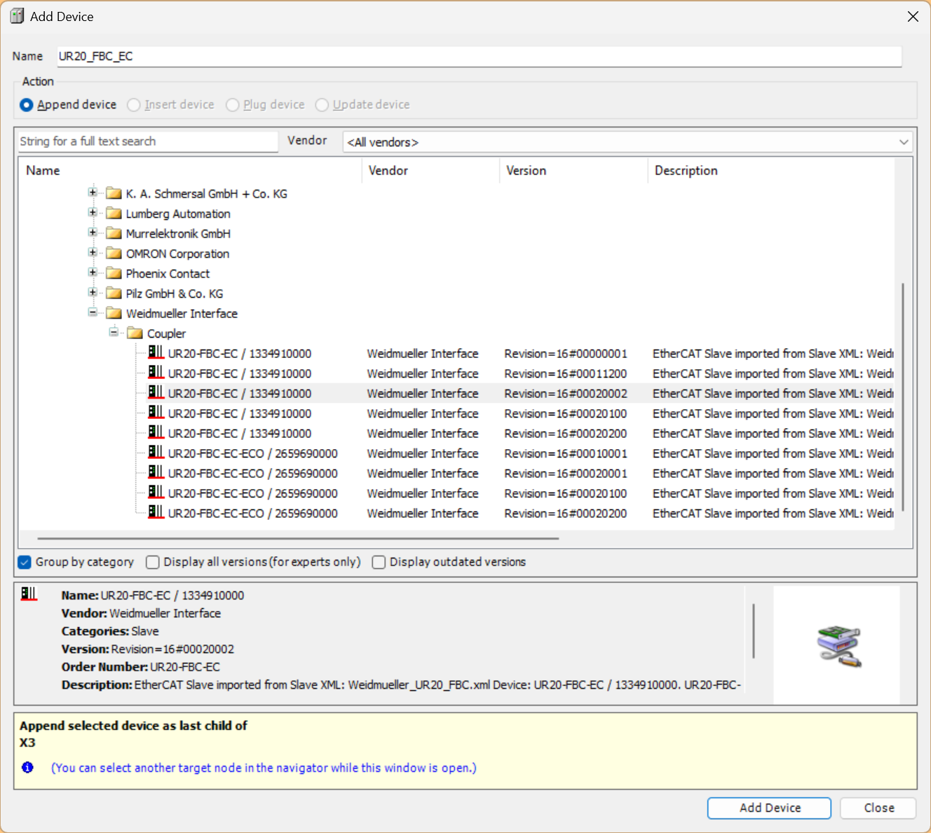
The one used in this article is UR20-FBC-EC/1334910000.
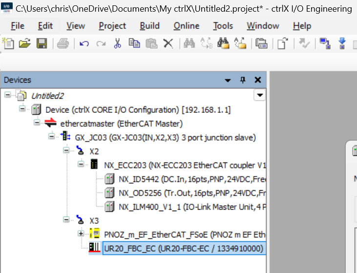
Done! The Weidmuller EtherCAT Coupler UR20-FBC-EC/1334910000 has been added.
Add Slot1 – UR20‐4DI‐4DO‐PN-FSOE-V2
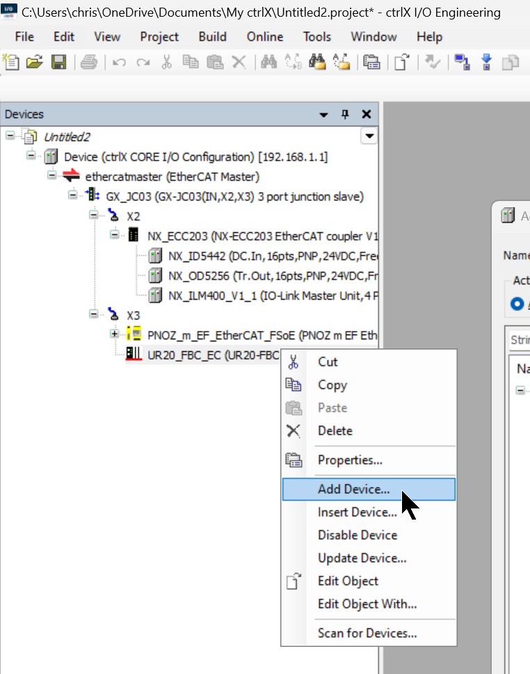
To add the UR20‐4DI‐4DO‐PN-FSOE-V2 installed in Slot1 of the Weidmuller EtherCAT Coupler, right-click on UR20-FBC-EC/1334910000 > Add Device.
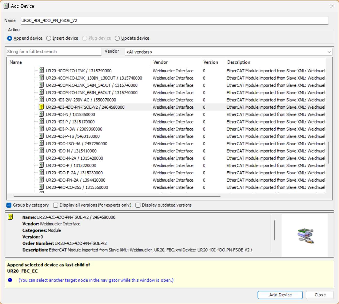
Let’s add UR20‐4DI‐4DO‐PN-FSOE-V2.
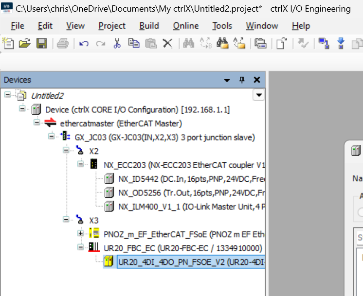
Done!
Add Slot2/3 – UR20‐8DI‐PN-FSOE-V2
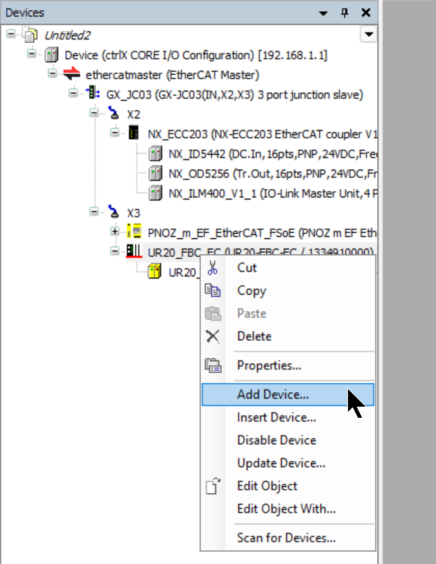
To add the UR20‐8DI‐PN-FSOE-V2 installed in Slot2 and Slot3 of the Weidmuller EtherCAT Coupler, right-click on UR20-FBC-EC/1334910000 > Add Device.
Let’s add UR20‐8DI‐PN-FSOE-V2.
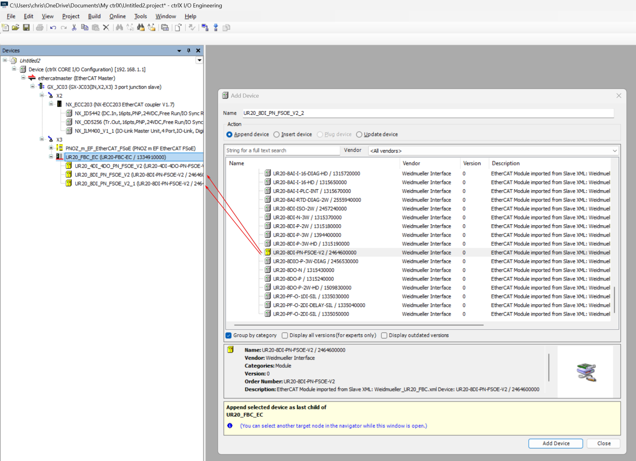
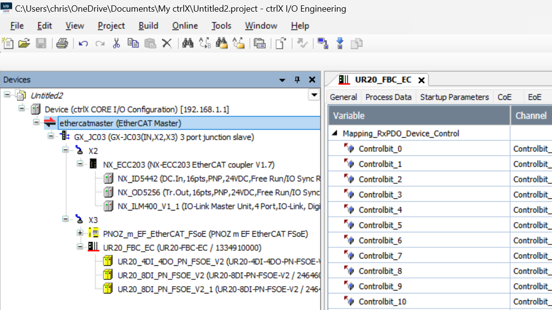
Result
Done! All Slaves in the EtherCAT network have now been added.
Configure Slave to Slave Connection
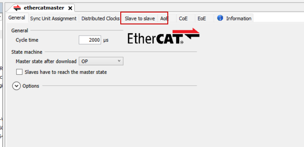
The inputs and outputs of the PNOZ m EF EtherCAT FSoE and the Weidmuller FSoE Slaves need to be loopbacked to each other. We used to write programs in Codesys, but ctrlX has a feature called “Slave to Slave” that allows data to be passed directly between Slaves.
Open the EtherCAT > Slave to slave Tab.
This is the Slave to slave feature screen in ctrlX IO Engineering.
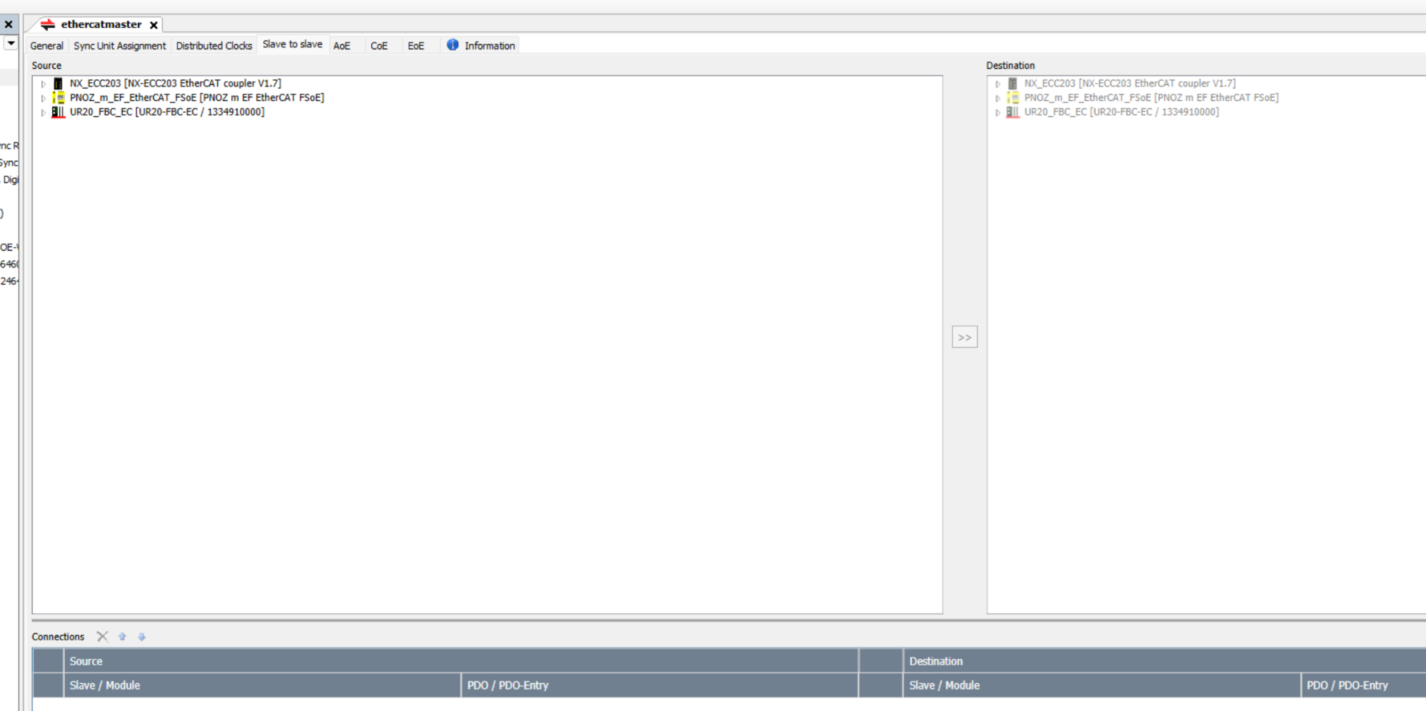
PNOZ m EF EtherCAT FSoE Slot1→Slot1 UR20_4DI-4DO_PN_FSOE-1
To transfer the 0x1A00 TxPDO input data of Slot1 of PNOZ m EF EtherCAT FSoE to the 0x1600 output data of Slot1 of UR20_4DI-4DO_PN_FSOE-1:
- In the Source side, select Slot1 > 0x1A00 of PNOZ m EF EtherCAT FSoE.
- In the Destination side, select Slot1 > UR20_4DI-4DO_PN_FSOE-1 > 0x1600 of UR20-FBC-EC/1334910000.
- Finally, click the >> arrow button.
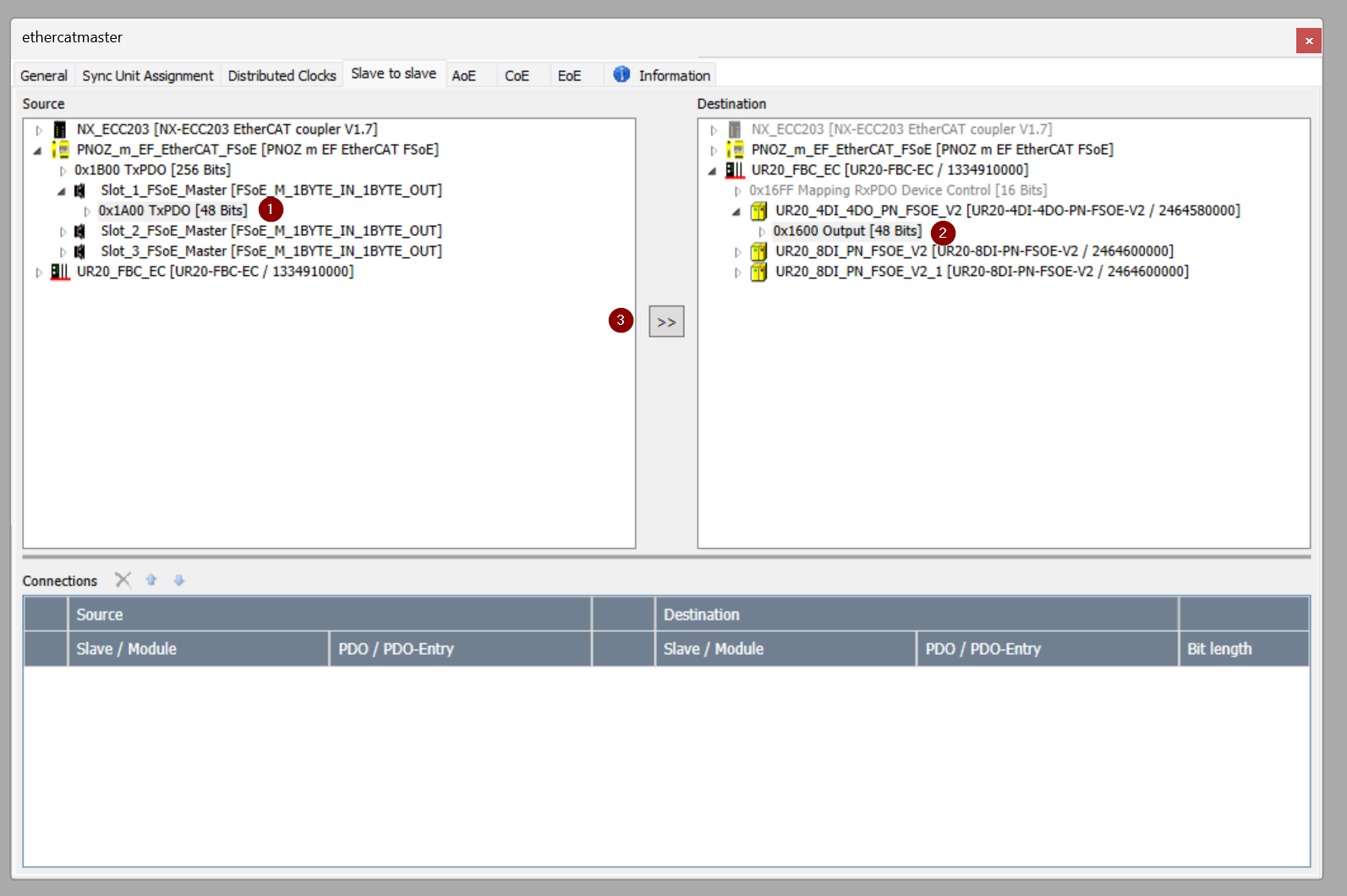
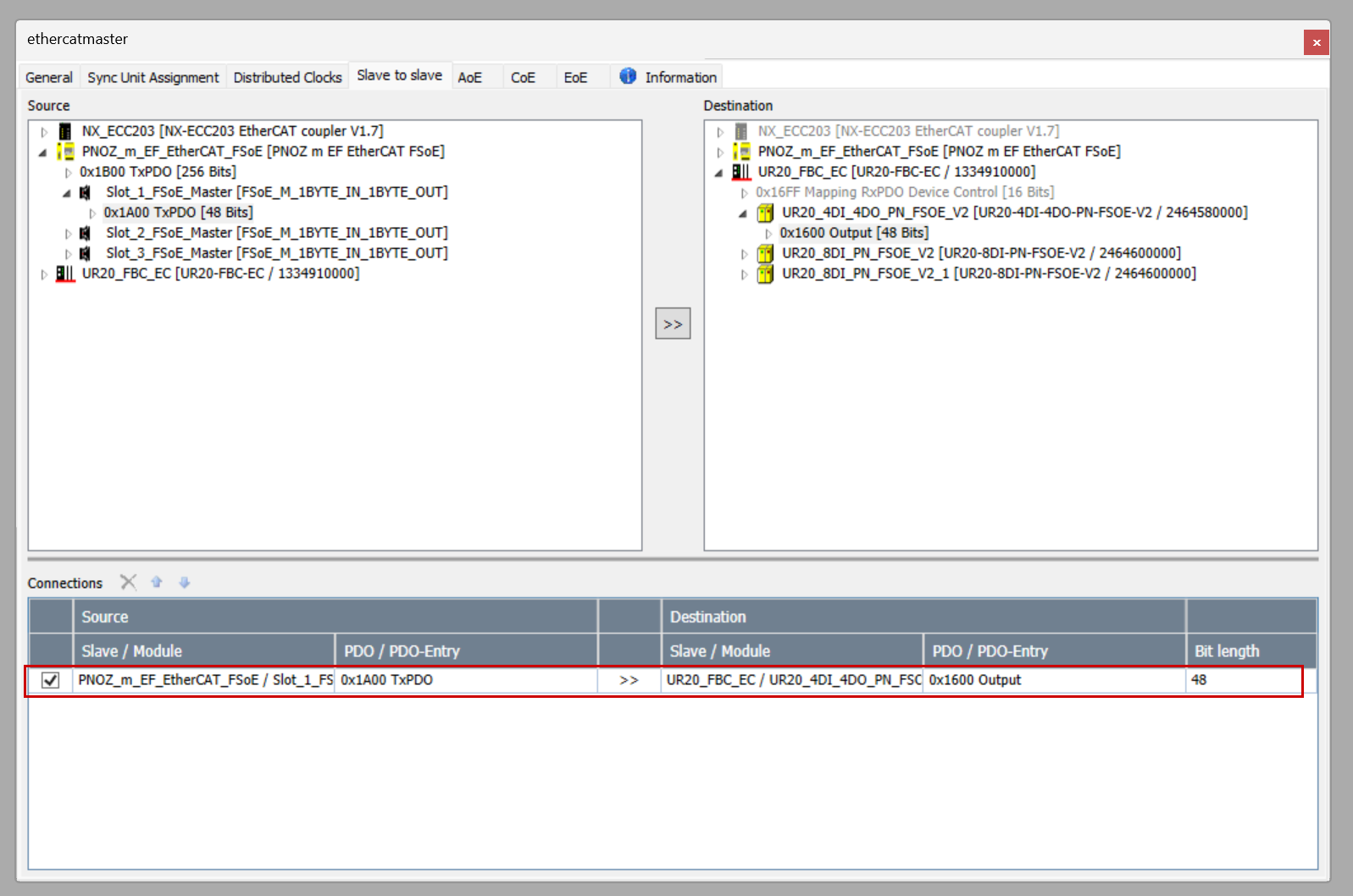
Done! Data transfer between Slaves is now possible with this alone.
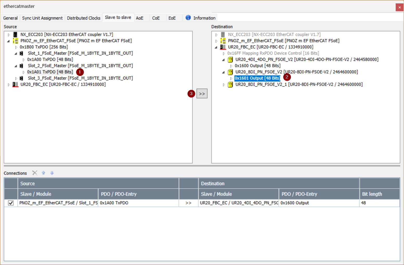
PNOZ m EF EtherCAT FSoE Slot2→Slot2 UR20_8DI_PN_FSOE
To transfer the 0x1A01 TxPDO input data of Slot2 of PNOZ m EF EtherCAT FSoE to the 0x1601 output data of Slot2 of UR20_4DI-4DO_PN_FSOE-1:
- In the Source side, select Slot3 > 0x1A01 of PNOZ m EF EtherCAT FSoE.
- In the Destination side, select Slot2 > UR20_8DI_PN_FSOE-1 > 0x1601 of UR20-FBC-EC/1334910000.
- Finally, click the >> arrow button.
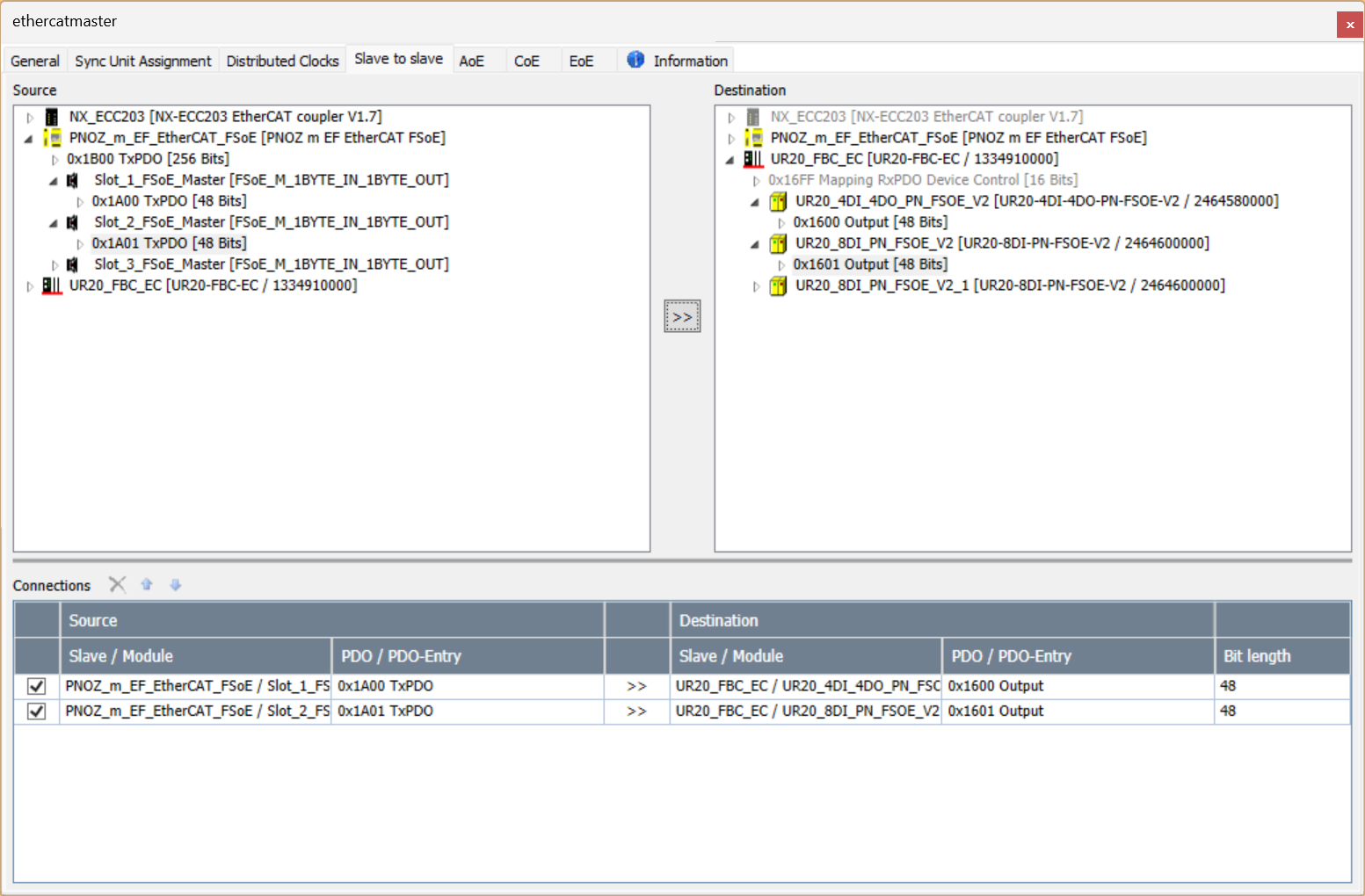
Done!
PNOZ m EF EtherCAT FSoE Slot3→Slot3 UR20_8DI_PN_FSOE
To transfer the 0x1A01 TxPDO input data of Slot of PNOZ m EF EtherCAT FSoE to the 0x1602 output data of Slot3 of UR20_4DI-4DO_PN_FSOE-2:
- In the Source side, select Slot3 > 0x1A02 of PNOZ m EF EtherCAT FSoE.
- In the Destination side, select Slot3 > UR20_8DI_PN_FSOE-1 > 0x1602 of UR20-FBC-EC/1334910000.
- Finally, click the >> arrow button.
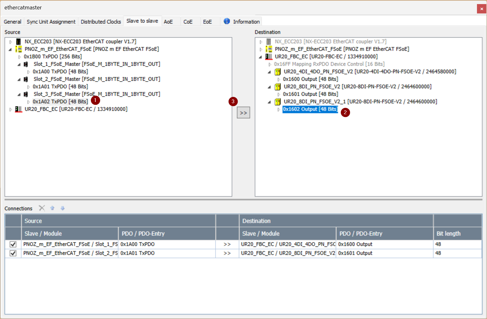
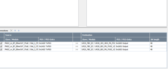
Done!
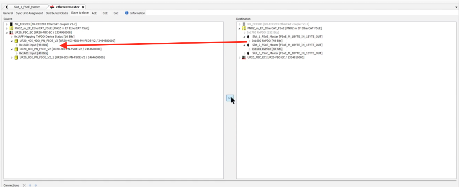
Slot1 UR20_4DI-4DO_PN_FSOE-1→PNOZ m EF EtherCAT FSoE Slot1
Now in the reverse direction.
To transfer the 0x1A00 TxPDO input data of Slot1 of UR20_4DI-4DO_PN_FSOE-1 to the 0x1600 output data of Slot1 of PNOZ m EF EtherCAT FSoE:
- In the Source side, select Slot1 > 0x1A00 of UR20_4DI-4DO_PN_FSOE-1.
- In the Destination side, select Slot1 > 0x1600 of PNOZ m EF EtherCAT FSoE.
- Finally, click the >> arrow button.
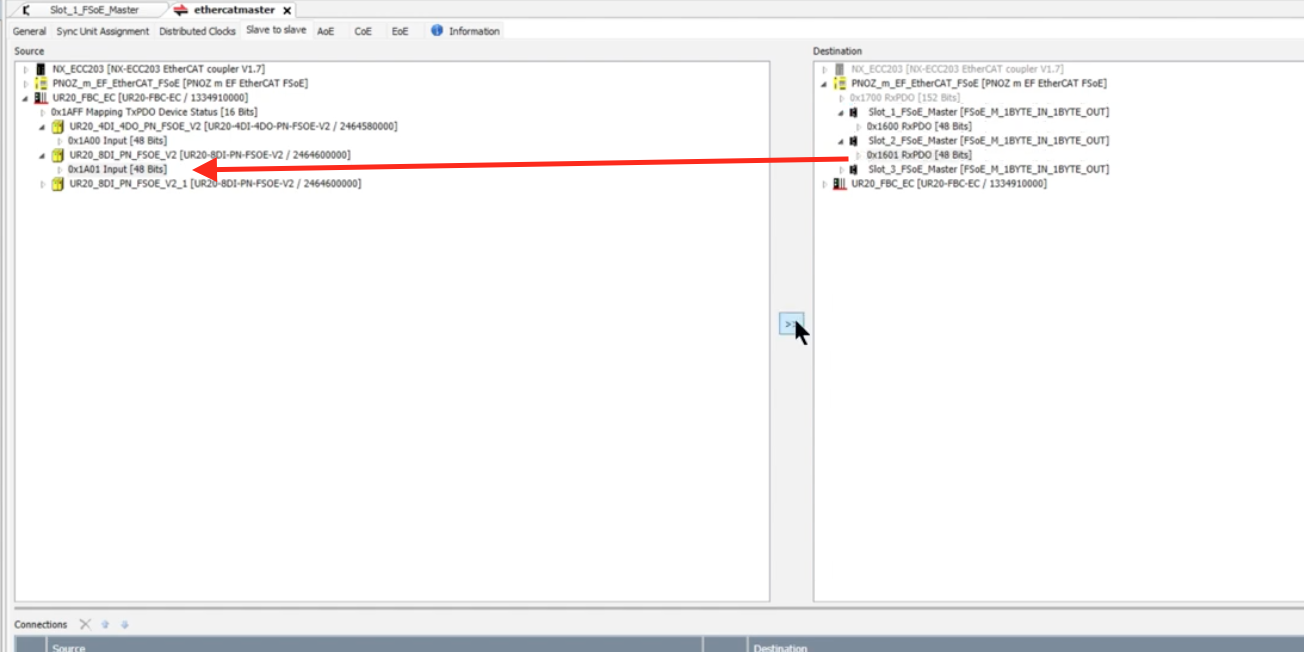
Slot2 UR20_8DI_PN_FSOE→PNOZ m EF EtherCAT FSoE Slot2
To transfer the 0x1A00 TxPDO input data of Slot2 of UR20_8DI_PN_FSOE-1 to the 0x1601 output data of Slot2 of PNOZ m EF EtherCAT FSoE:
- In the Source side, select Slot2 > 0x1A01 of UR20_8DI_PN_FSOE.
- In the Destination side, select Slot2 > 0x1601 of PNOZ m EF EtherCAT FSoE.
- Finally, click the >> arrow button.
Slot3 UR20_8DI_PN_FSOE→PNOZ m EF EtherCAT FSoE Slot3
To transfer the 0x1A00 TxPDO input data of Slot3 of UR20_8DI_PN_FSOE-1 to the 0x1602 output data of Slot3 of PNOZ m EF EtherCAT FSoE:
- In the Source side, select Slot3 > 0x1A02 of UR20_8DI_PN_FSOE.
- In the Destination side, select Slot3 > 0x1602 of PNOZ m EF EtherCAT FSoE.
- Finally, click the >> arrow button.
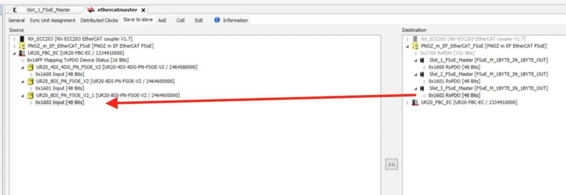
Result
Done!

Download
Finally, download the Configuration to the CPU.
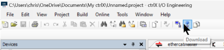
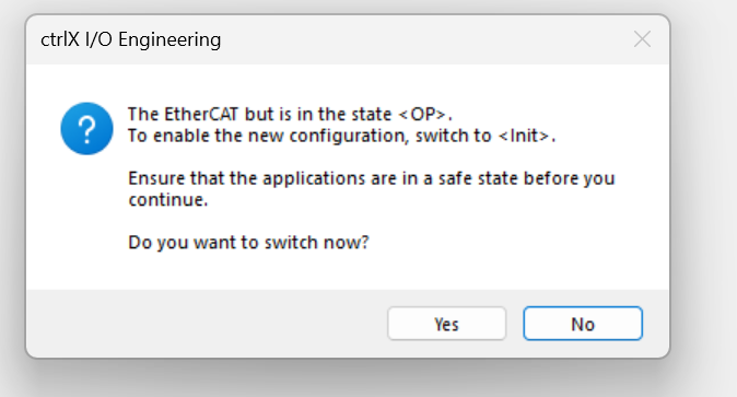
Changing the EtherCAT network configuration requires switching to the Init state. If the EtherCAT Master is already in the OP state, a warning will appear, so proceed with Yes.
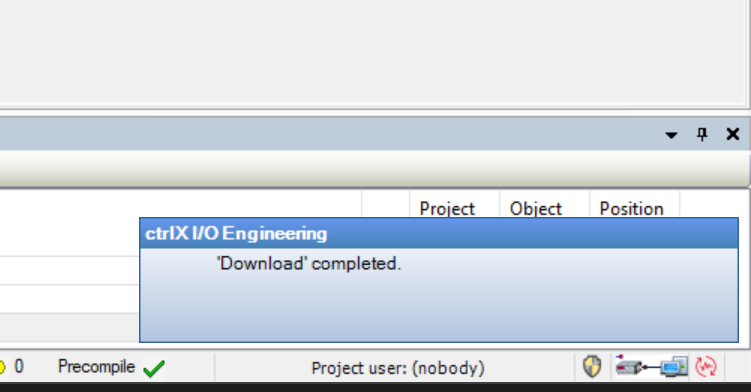
Done!
PLC Project
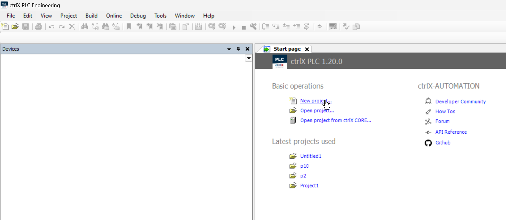
Now, to create a PLC project, open ctrlX PLC Engineering > Click New Project.
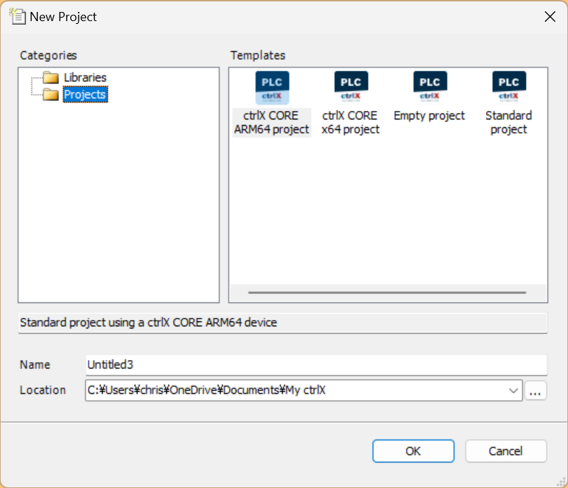
Projects > ctrlX CORE ARM64 project > Proceed with Ok.
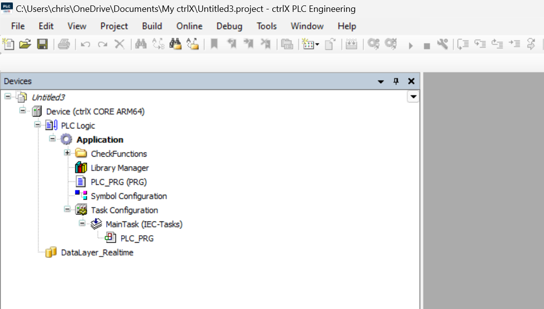
Done! A new PLC project has been added.
Configure RealTime Layer
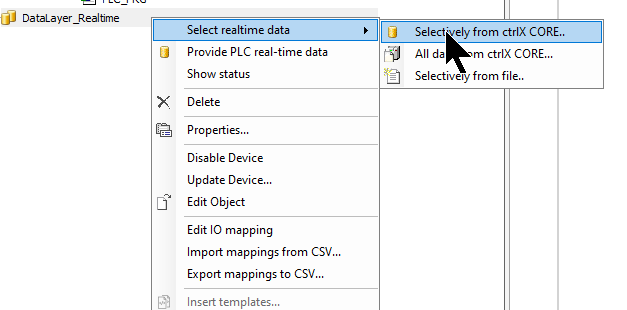
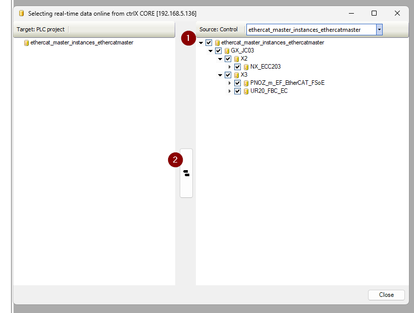
Next, to add the Realtime Data Layer variables (EtherCAT Master App in this article), click DataLayer_Realtime > Selectively from ctrlX CORE.
This is the Realtime Data Layer settings screen.
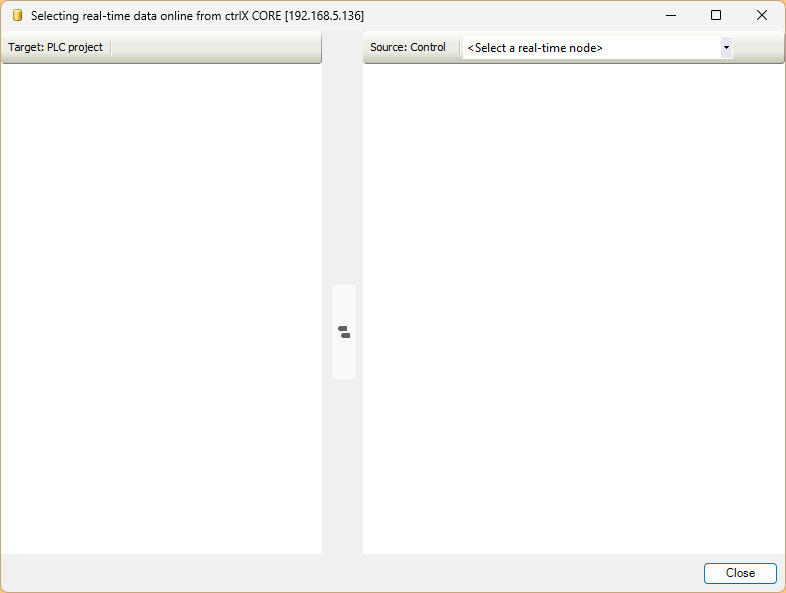
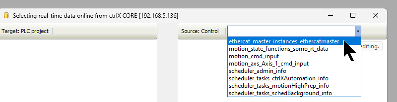
Select Ethercat_master_Instances_Ethercatmaster from the Source Control drop-down list.
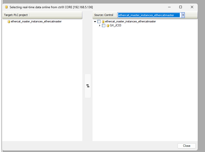
All EtherCAT app variables accessible via the Data Layer are displayed.
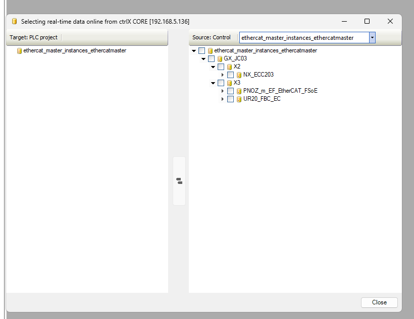
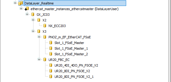
You can also directly access the Weidmuller EtherCAT Coupler and Pilz PNOZ m EF EtherCAT FSoE via DataLayer_Realtime.
Select all variables > Click the button indicated by 2 to import the variables into the project.
Done!
GVL
Define the Global Variable List to map with the EtherCAT Slave data.
{attribute ‘qualified_only’}
|
|---|
Program
This is the program that receives signals such as emergency stop.
PROGRAM PLC_PRG
|
|---|
Mapping
Map the variables defined in the Global Variable List to the DataLayer_Realtime data.
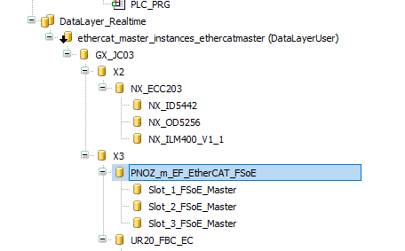
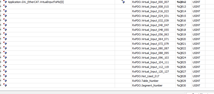
Map the GVL variables to the Pilz FSOE Master.
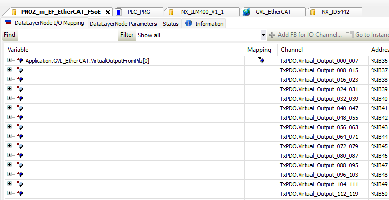
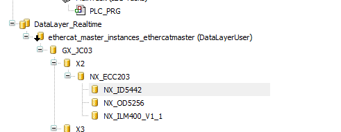
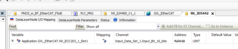
Map the GVL variables to the OMRON EtherCAT Coupler.
Login
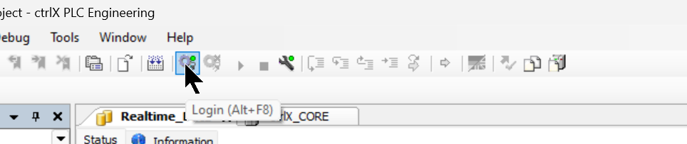
Click the Login button to download the project.
Proceed with OK.
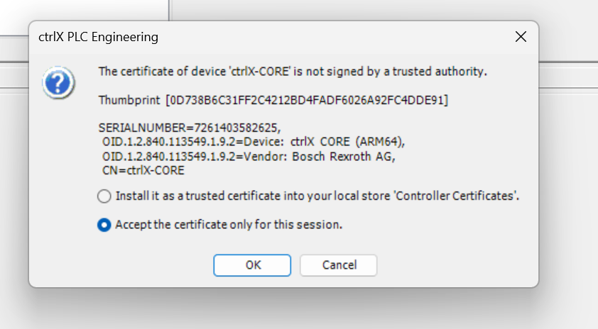
Proceed with Ok again.
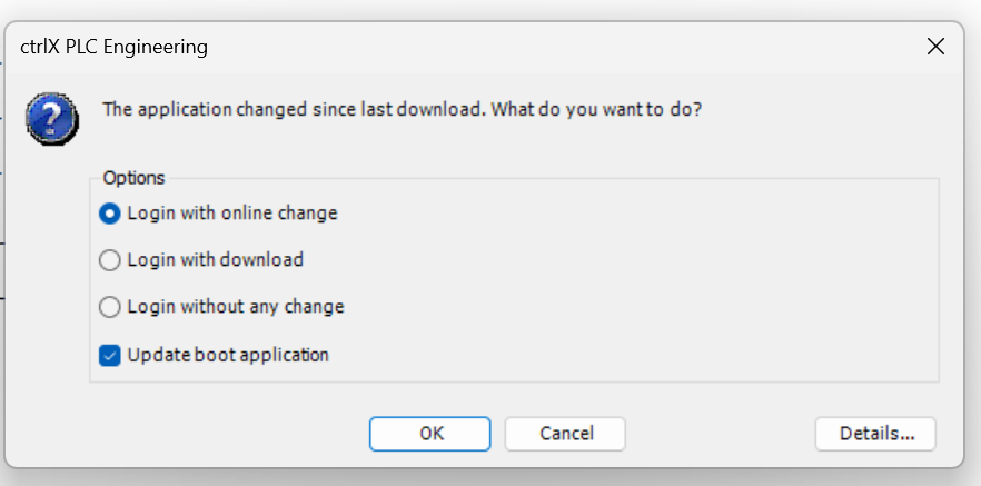
Pilz Side
Next, we will configure the Pilz PNOZ m EF EtherCAT FSoE side. This controller is responsible for the actual FSoE safety communication and safety program.
Import ESI File
Open the EtherCAT/FSoE Tab in PNOZmulti Configurator.
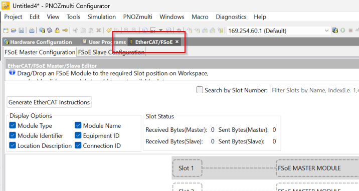
Click “Import ESI Files” from the EtherCAT/FSoE Slave Library on the right to add the ESI File.
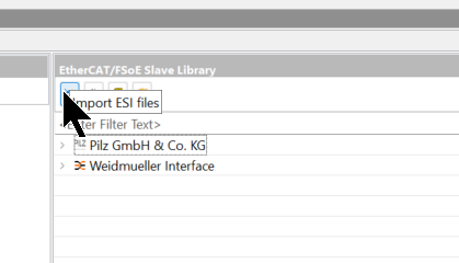
Let’s import the Weidmüller ESI File.
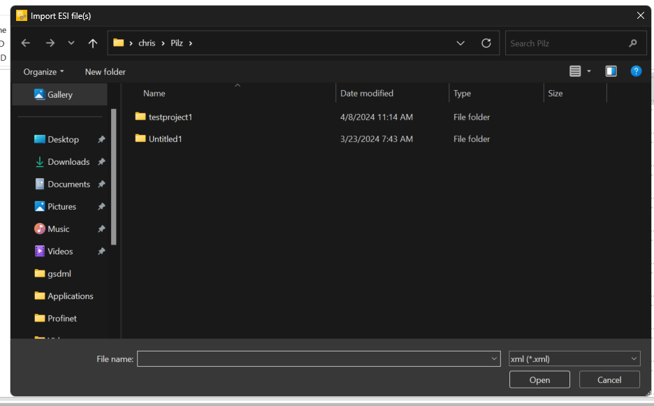
Done!
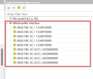
Configure FSOE Connection
Next, configure the FSoE safety communication in Tools > EtherCAT/FSOE > EtherCAT/FSoE Configuration.
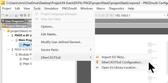
As shown in the figure below, Slot1/Slot2/Slot3 are configured to connect to the Weidmuller FSoE Slaves.
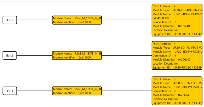
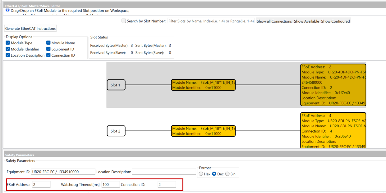
FSoE ConnID/Address
The FSoE Address is set according to the rotary switch on the side of the Weidmuller FSoE Slave. Set the ConnID so that it does not overlap within the network.
Parameter
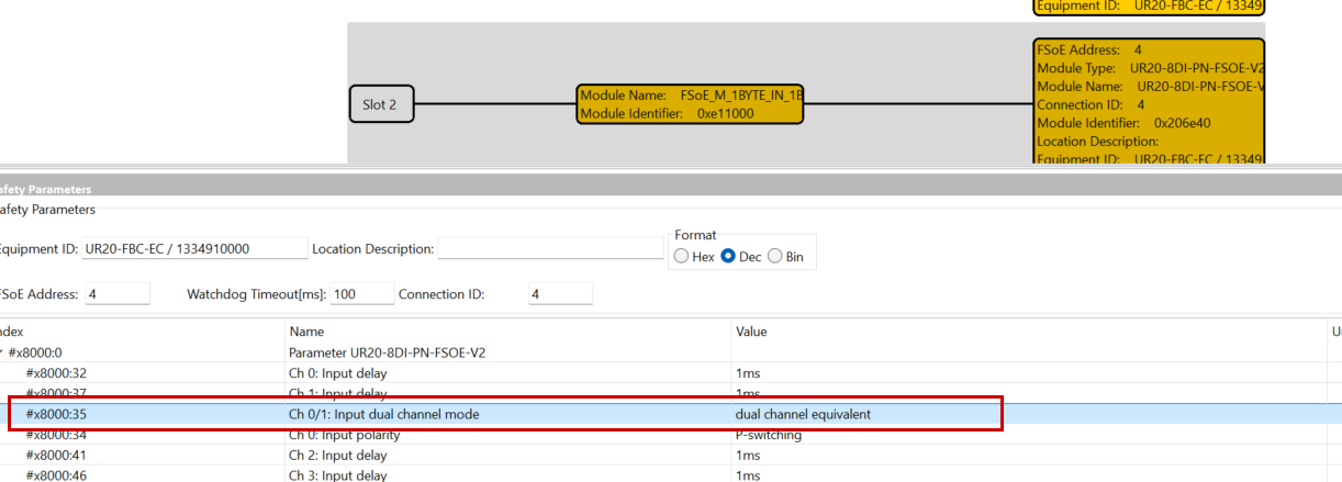
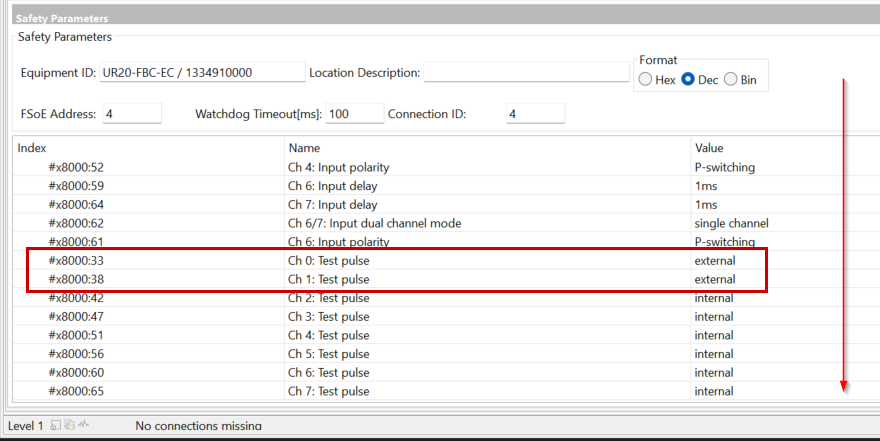
In this article, since the Weidmuller FSoE Slave is connected to a Keyence light curtain, the Pulse Test setting must be disabled for the safety input.
The Keyence light curtain is connected to inputs 0 and 1 of Slot2.
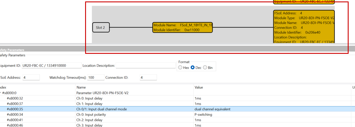
#8000.35 of Input dual channel mode to Dual channel equivalent (since two OSSD inputs come simultaneously).
Next, set the Test pulse of #8000.33 and #8000.38 to External.
Program
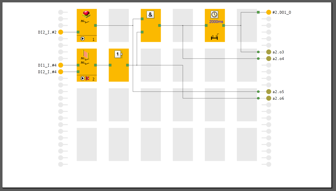
Finally, create a simple safety program. In this program:
- If both emergency stop and light curtain are input simultaneously, wait for a 2-second delay and then set the safety output #2.D01_0 to True.
- If the emergency stop is ON, output to non-safety communication a2.o5 (Bit 5 of Byte 0).
- If the light curtain is input, output to non-safety communication a2.o6 (Bit 6 of Byte 0).
- If both emergency stop and light curtain are input simultaneously, output to non-safety communication a2.o4 (Bit 4 of Byte 0).
- If both emergency stop and light curtain are input simultaneously, output to non-safety communication a2.o3 (Bit 3 of Byte 0) after a 2-second delay has passed.
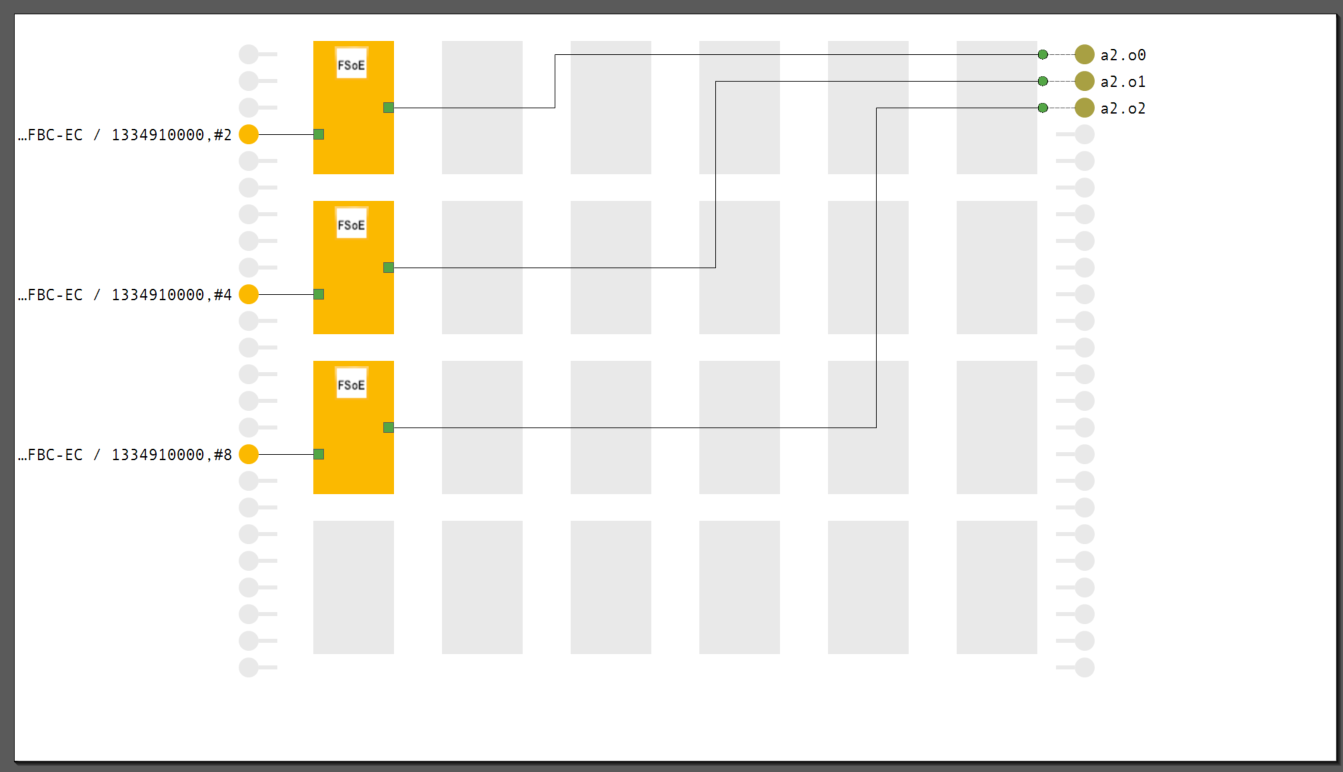
This program sends feedback on the safety communication status of each FSoE Slave to ctrlX via EtherCAT.
- If the FSoE Slave with FSoE Address=2 is safety communication OK, output to non-safety communication a2.o0 (Bit 0 of Byte 0).
- If the FSoE Slave with FSoE Address=4 is safety communication OK, output to non-safety communication a2.o1 (Bit 1 of Byte 0).
- If the FSoE Slave with FSoE Address=8 is safety communication OK, output to non-safety communication a2.o2 (Bit 2 of Byte 0).
Download
To download the project, click PNOZmulit > Project Manager.
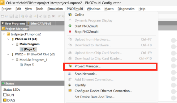
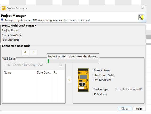
The Download screen will be displayed.
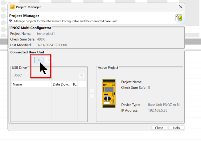
Click the button in the red frame to download the project.
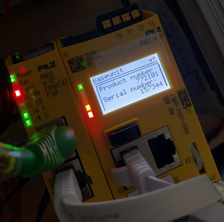
Enter the Order Number and Serial Number of the CPU.
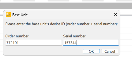
The Order Number and Serial Number can be confirmed on the CPU screen.
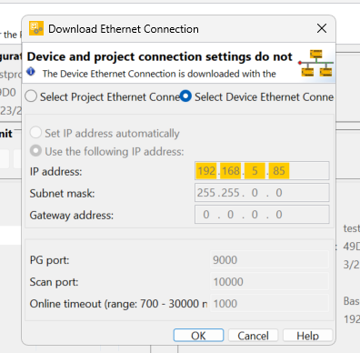
Since we want to change the Ethernet Connection, click “Select Device Ethernet Connection” and proceed with OK.
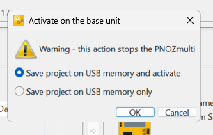
Select “Save project on USB Memory and activate” and proceed with Ok.
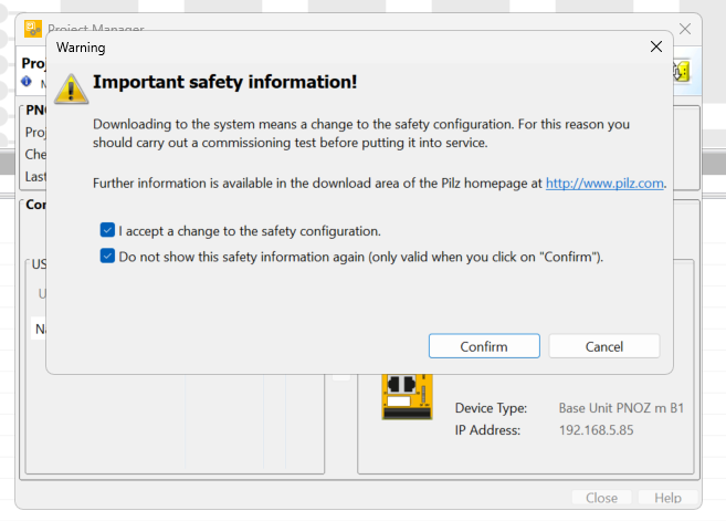
Confirm the notes and proceed with Confirm.
The download will start, so please wait for a while.
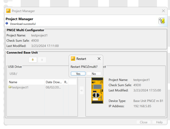
A confirmation screen appears asking if you want to restart the PNOZmulit CPU from the tool, proceed with Yes.
Result
The PLC program successfully received the emergency stop and OSSD signals.
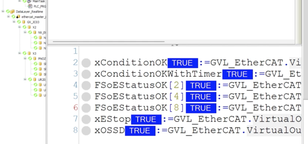
Operation confirmation can be seen in this video.