This is a new article series where we conduct various verifications using UNITRONICS’ UniStream® series and UniLogic. In Episode 3, we will create a screen and display program variables from UniStream’s HMI+PLC integrated device.
The following device is used in Episode 3:
- UNITRONICS’ US5-C10-TA30
Now, let’s enjoy FA!

Reference Link
Implementation 1 – Screen Creation
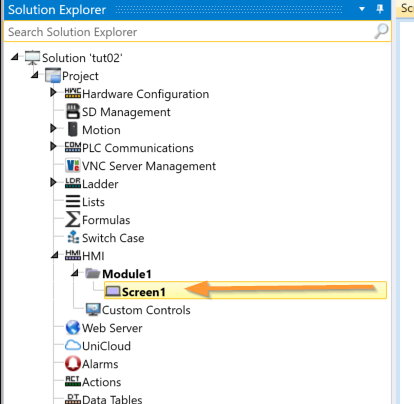
This time, let’s try creating a screen from UniLogic. Click HM → Module1 → Screen1.
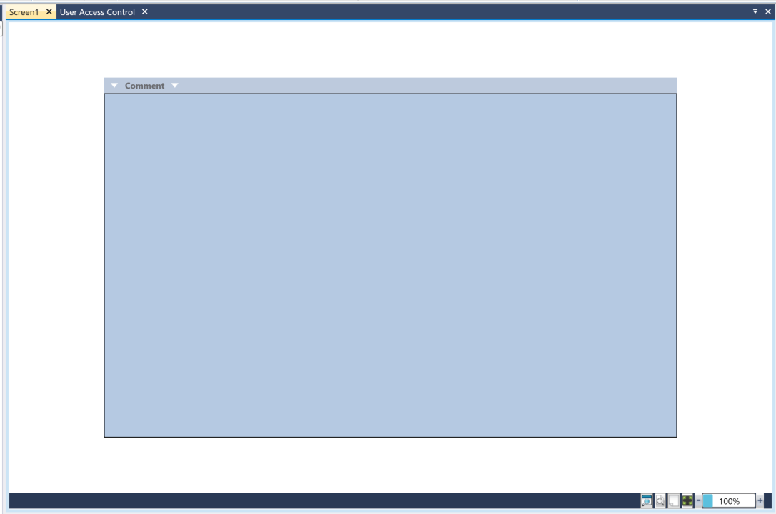
This is the UniLogic Screen Editor.
Adding a Button
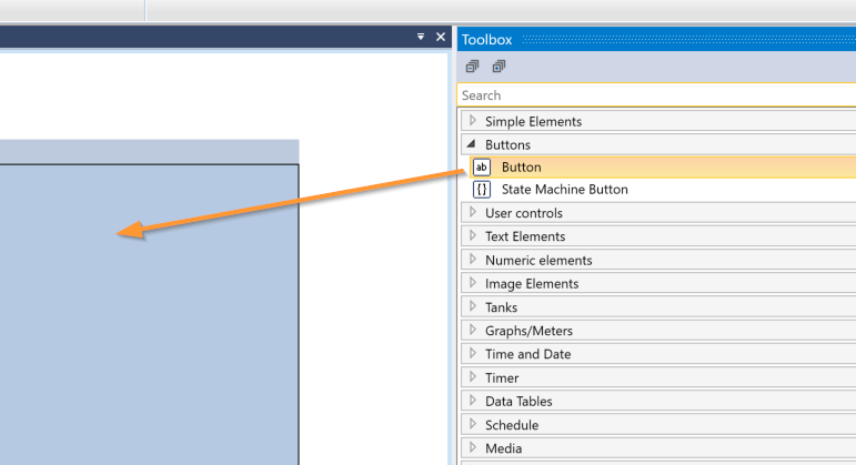
First, we will add a simple button to the screen. Click Toolbox → Buttons → Button.
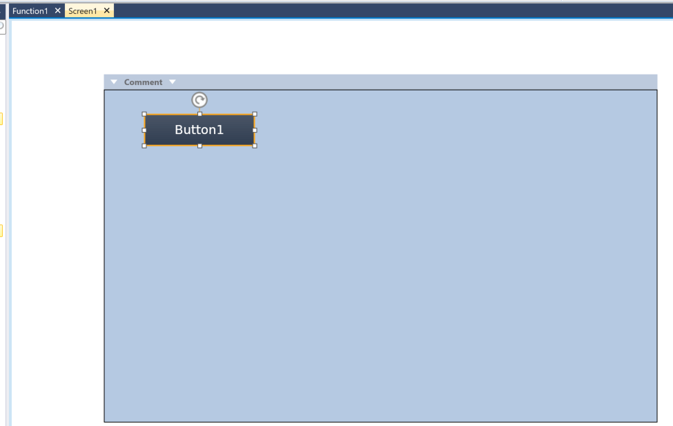
Done! The button has been added.
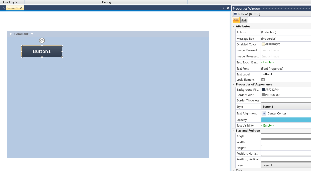
The Properties Window is on the right side of UniLogic, where you can change the settings of the component.
Button Text
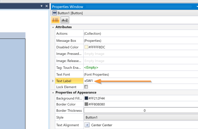
First, change the button text from Properties Window → Text Label.
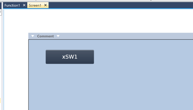
Done!
Action
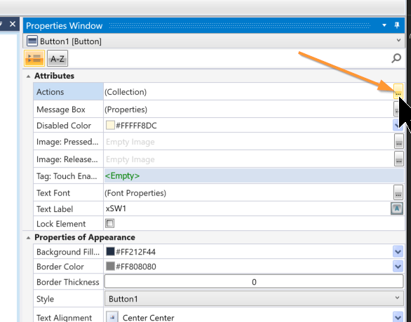
Next, add the action that occurs when the HMI button is pressed. Click the … button next to Properties → Actions.
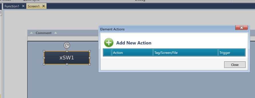
This is the action addition screen.
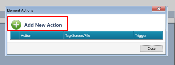
Click “Add New Action” shown in the figure below.
A new action is added.
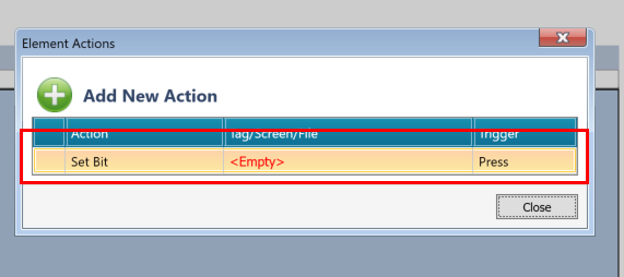
The action that occurs when the button is pressed can be set from the Action Drop-list.
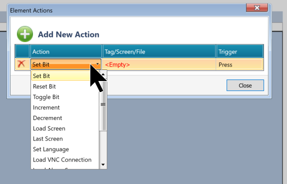
First, set it to Set Bit.
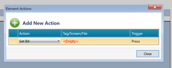
Next, assign the Bit variable to be set when the button is pressed in the Tag/Screen/File field.
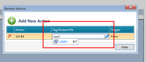
Done!
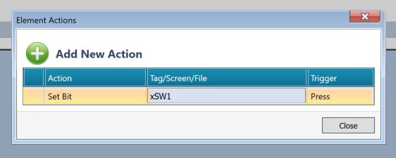
Finally, set the action to be triggered in the Trigger field.

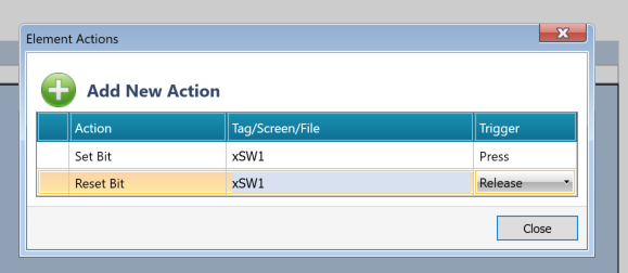
Done! In this example, when the button is pressed, xSW1 is set to True, and when the button is released, xSW2 is set to False.
Adding Binary Text Variable
Next, we will change the displayed text based on the False/TRUE value of the Bool variable.
Add a Binary Text Variable from the Toolbox.
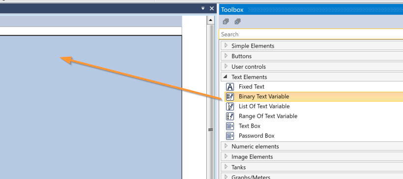
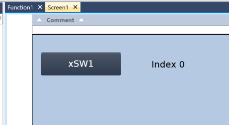
Done! The Binary Text Variable component has been added.
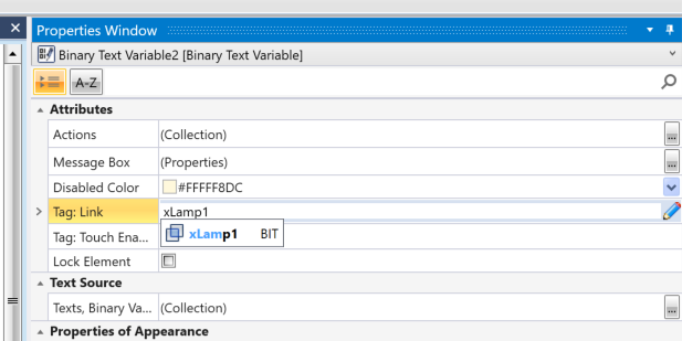
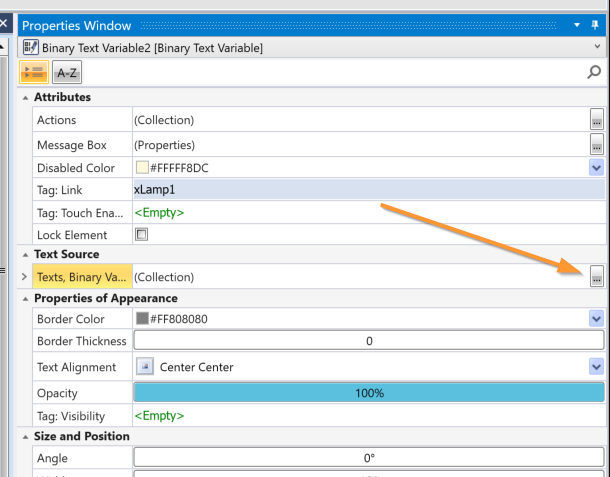
Next, assign it to a program variable using Properties → Tag:Link.
Next, click the button shown in the figure below to set the text to be displayed.
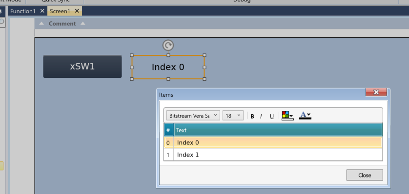
The settings screen is displayed.
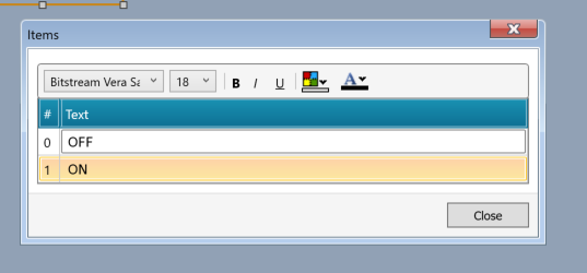
Set it to display 0=OFF and 1=ON as shown in the figure below.
Next, you can also change the color based on the Bool value.
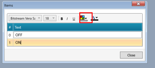
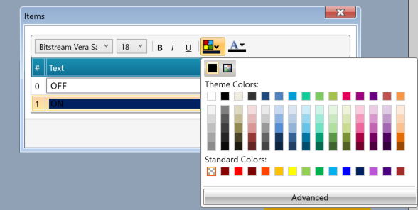
Done! Currently, 0=gray OFF and 1=orange ON.
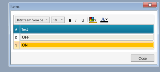
Result
You can check the operation from this video.
Implementation 2 – Message Box
In Implementation 3, we will add a message box to the screen. This allows you to display a reconfirmation POPUP screen before performing an action such as a button press. Click the … button in the Properties Window → Message Box of the button.
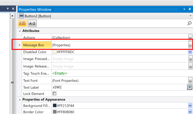
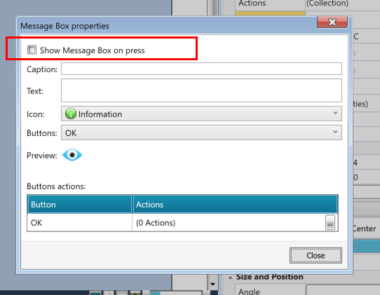
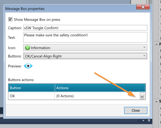
This is the message box settings screen.
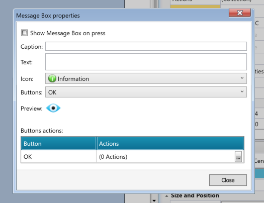
Check “Show Message Box On Press” in the figure below.
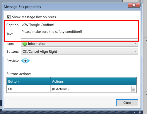
Next, set the title and displayed text of the message box.
Set the button items to be displayed in the corresponding message box from the Button Drop-list.
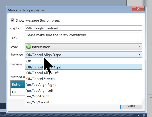
In this article, we set the display on the right side with OK/Cancel.
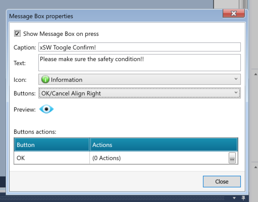
Next, set the action to be triggered when OK is pressed in the Button Actions section.
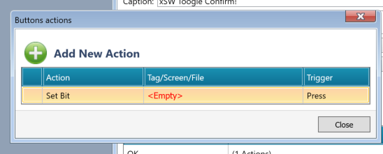
The same action setting screen as before is displayed.
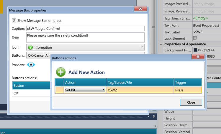
This time, we set the action to set xSW2 to TRUE when the OK button is pressed.
Result
You can check the operation from this video.
Implementation 3 – VNC Server
Next, we will enable the VNC server function of the US5-C10-TA30 from UniLogic.
Enabling VNC Server Function
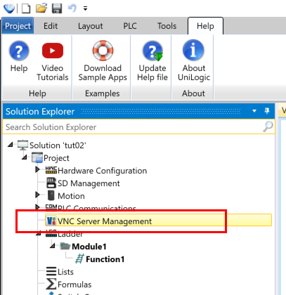
Project → VNC Server Managementをクリックします。
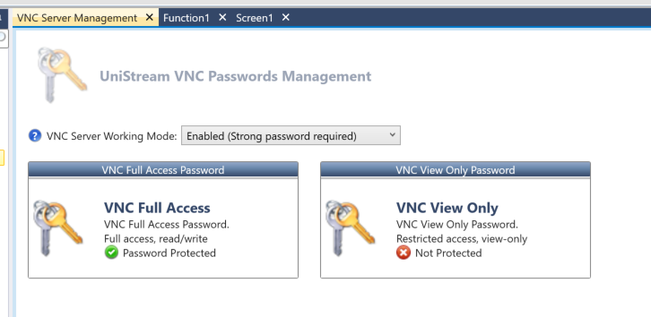
This is the UniLogic VNC Server settings screen.
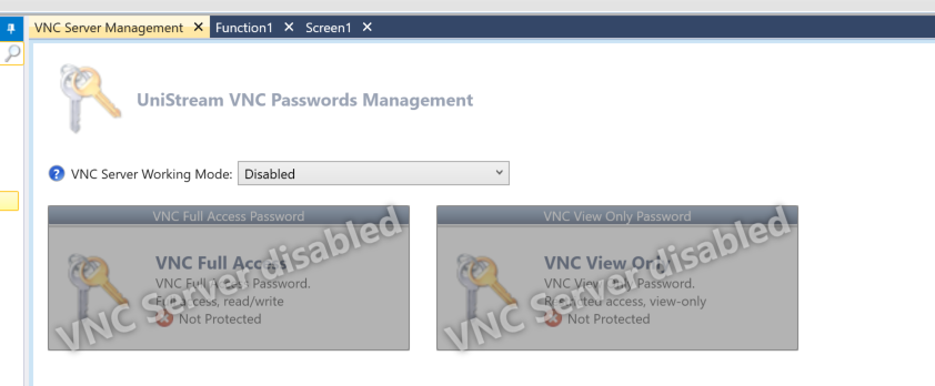
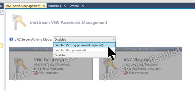
Select Enable(Strong password required) from the VNC Server Working Mode Drop-List.
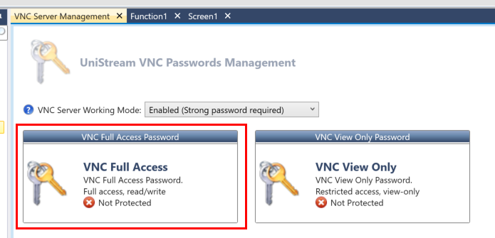
Next, click VNC Full Access Password.
Set the Password.
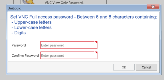
You can check the password currently entered from the eye mark in the Password field.
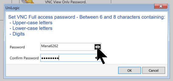
Done!
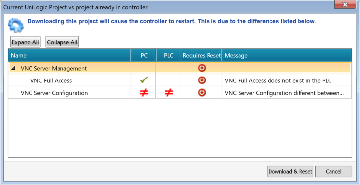
Note that enabling the VNC Server requires a download reset of the PLC.
IP Settings
Next, set the IP address of the US5-C10-TA30.
Project → PLC Communications → Physical → Panel Etherentをクリックします。
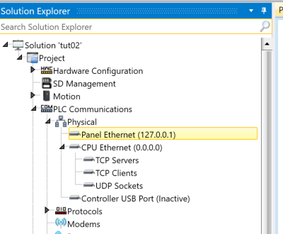
This is the device’s network settings screen.
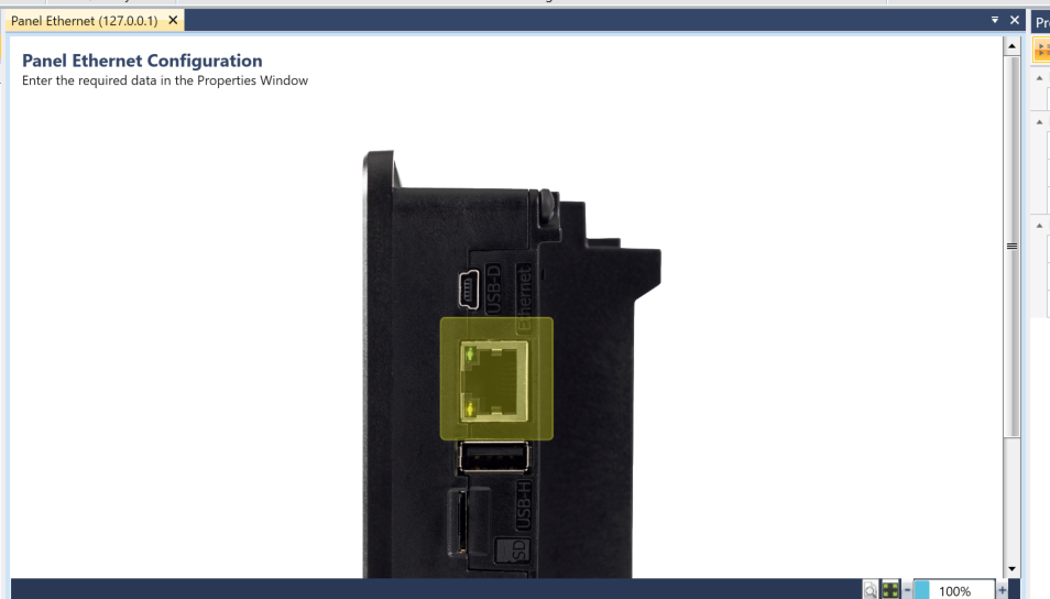
You can set the device’s IP address from the Properties Window.
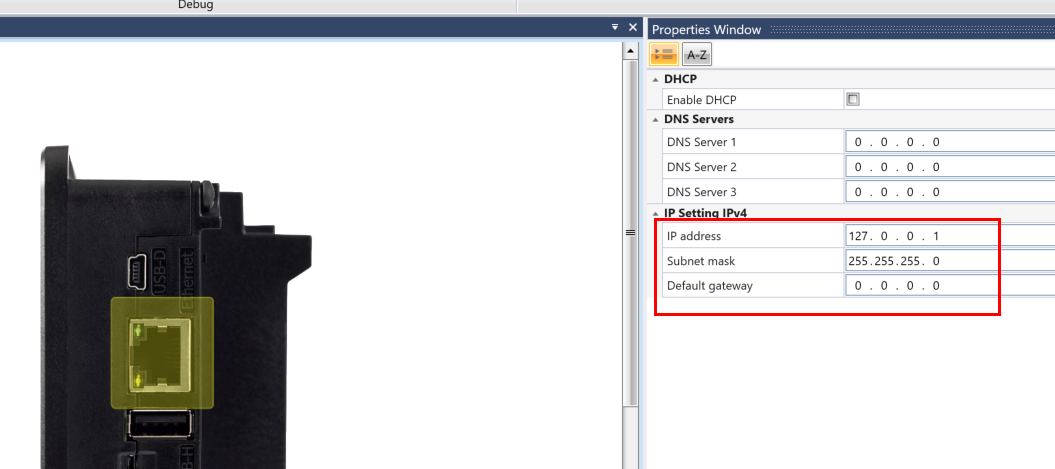
Result
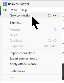
Click File → New Connection.
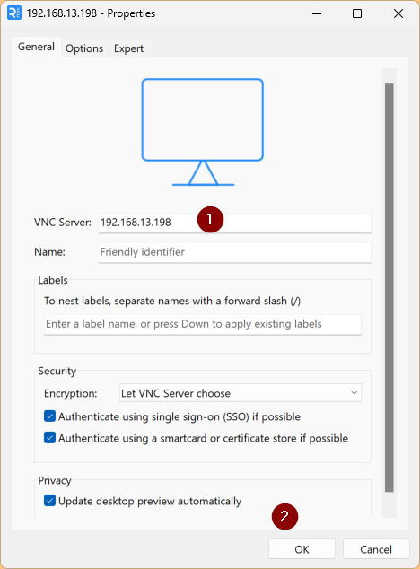
Enter the IP address in the VNC Server and click OK.
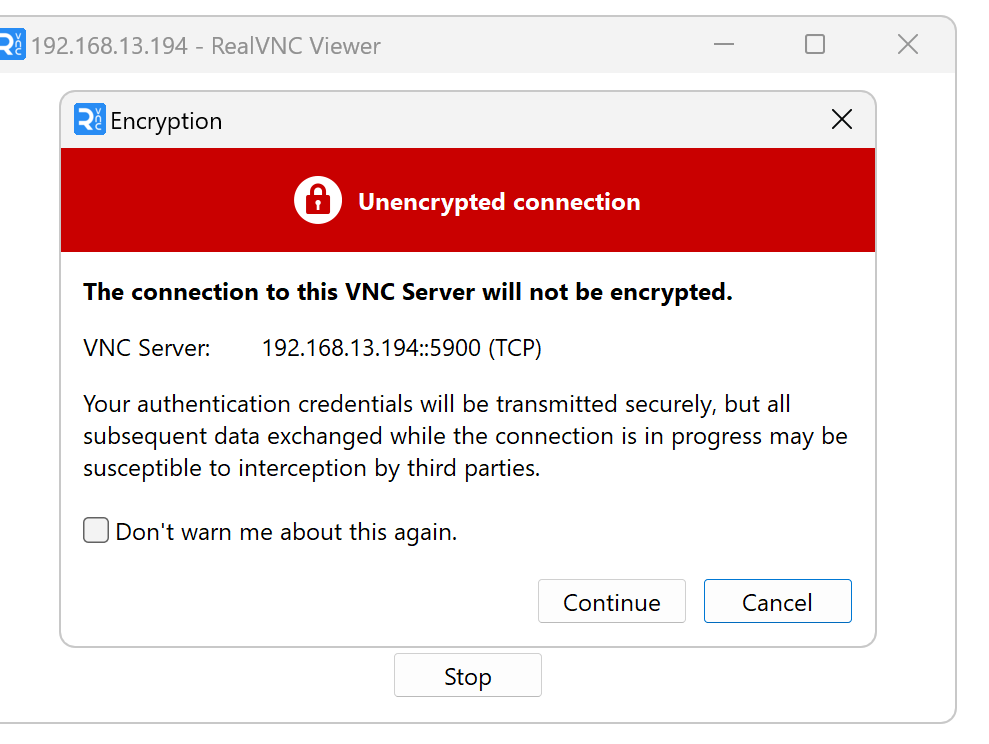
Click Continue.
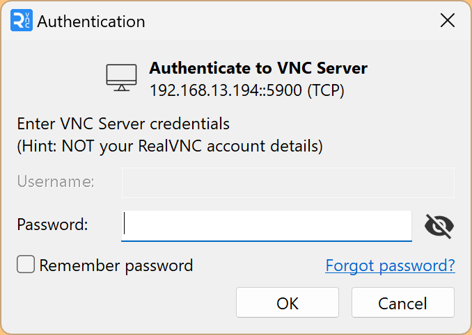
If you enter the Password you set earlier and click OK, you can access the VNC Server of the US5-C10-TA30.
Implementation 4 – Numeric Display
Next, let’s try adding a numeric display. Drop Numeric Box from Toolbox → Numeric elements onto the screen.
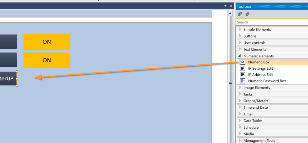
Done! The Numeric Box has been added.
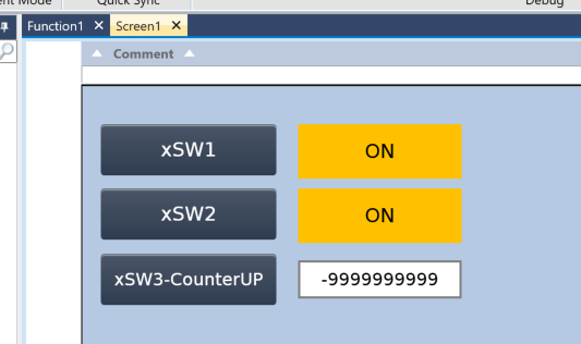
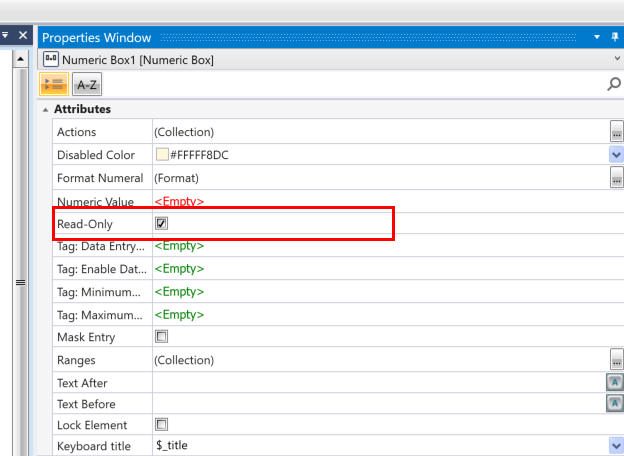
In Implementation 4, we want the component added earlier to be read-only, so uncheck the “Read Only” checkbox in Properties.
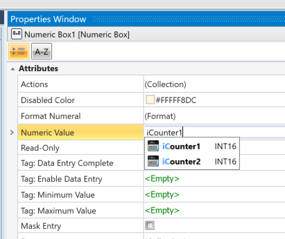
Next, assign the variable to be displayed in the Numeric Value field.
Result
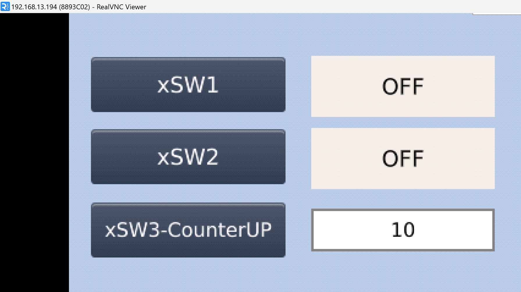
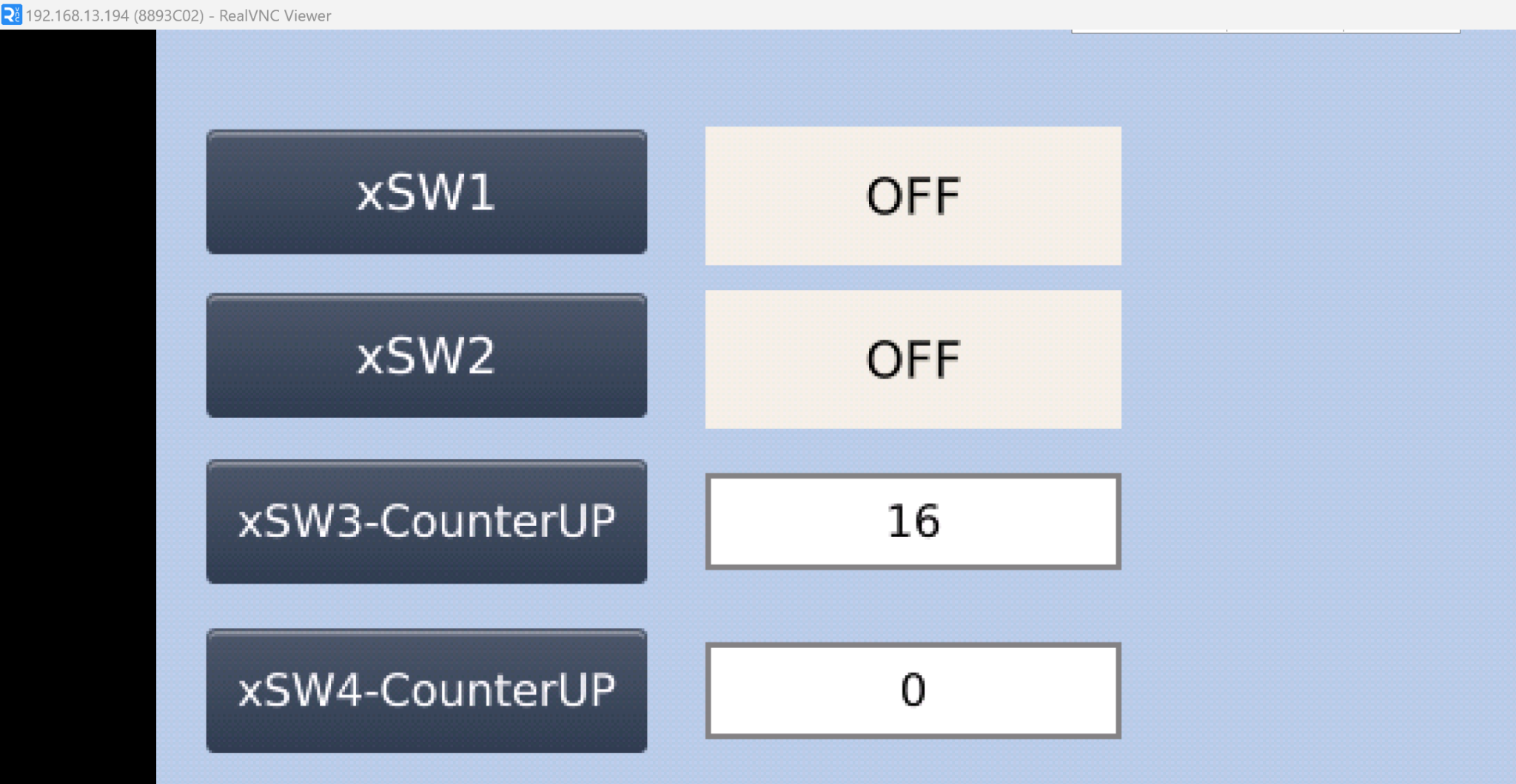
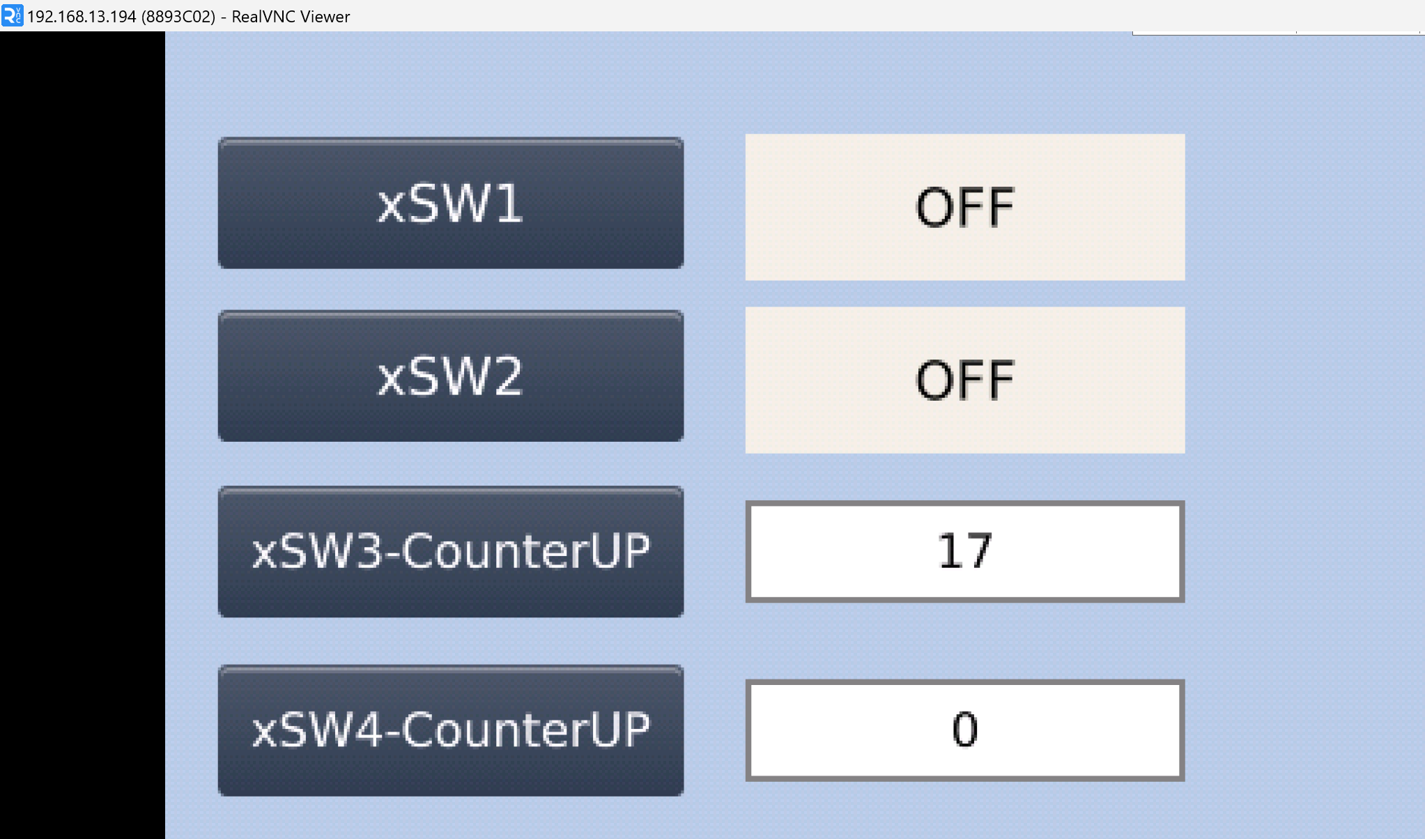
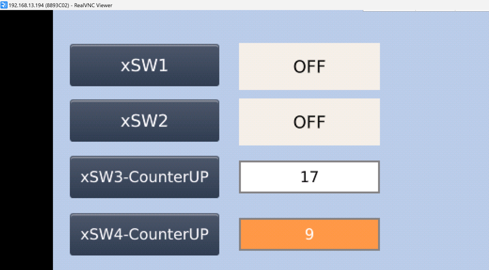
As shown in the figure below, every time xSW3-CounterUP is pressed, the numeric display increases by 1.
Implementation 5 – Numeric Box Write
This time, we will use the same Numeric Box, but we will make it possible to change the current value of the variable from the screen.
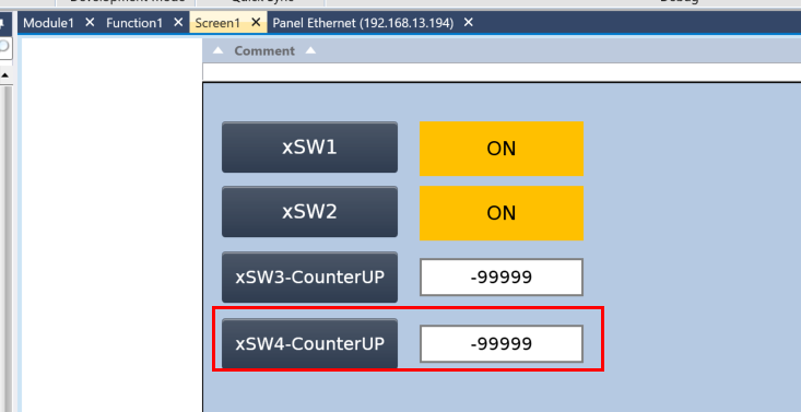
The setting method is very simple: uncheck the Read Only checkbox in the Properties Window.
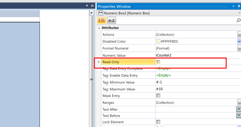
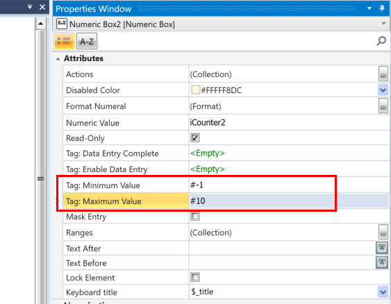
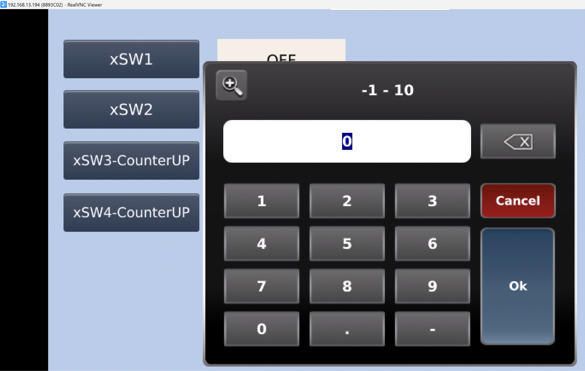
Also, to prevent operator error, let’s set limits for the input.
- Minimum Value is the minimum input; this time, we set it to -1.
- Maximum Value is the maximum input; this time, we set it to 10.
Also, you can change the display color based on the current Tag range using the Ranges setting.
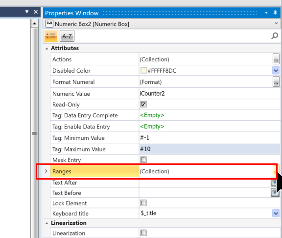
This is the Numeric Box range setting screen.
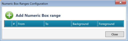
Click the plus button.
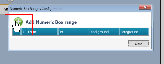
Done! A new range setting has been added.
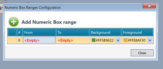
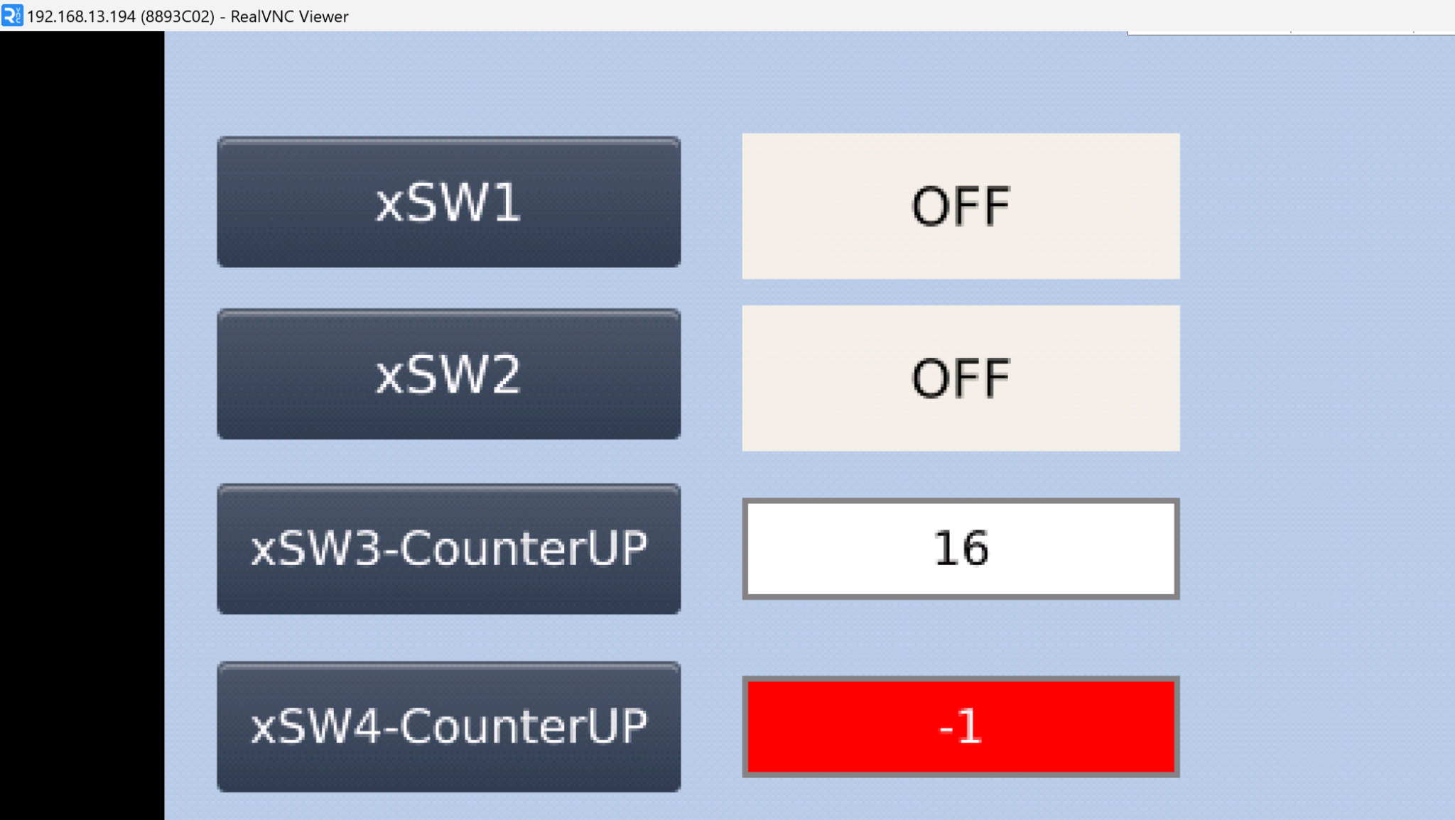
For example, as shown in the figure below, you can set the background color to red and the text color to white when the current value is from -99 to -1.
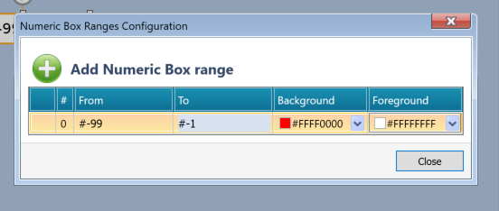
Done!
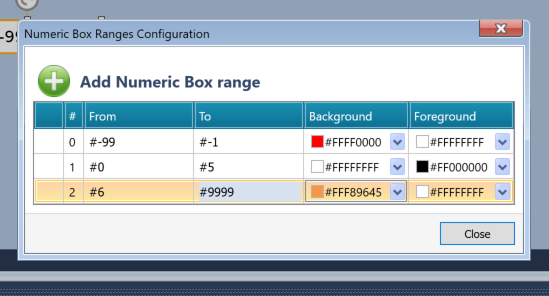
Result
Now, let’s actually look at the result.
When entering a value in the Numeric Box, the Min/Max values are also displayed in the Popup.
If the current value is -1, the background will be red and the text will be white according to the previous setting.
If the current value is 0, the background will be white and the text will be black according to the previous setting.
If the current value is 9, the background will be orange and the text will be white according to the previous setting.
Implementation 6 – Timer Box
Finally, we introduce the Timer Box component. It’s one of my favorite components. Displaying the current timer value on the HMI is quite troublesome, but with UniLogic, using the Timer Box easily solves this.
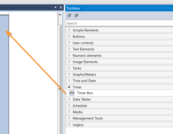
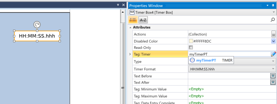
Assign the Timer variable in the program to Properties → Tag:Timer.
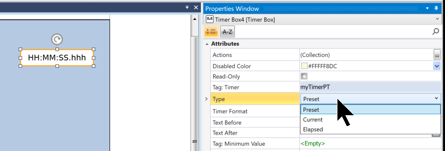
Properties → Type, you can set the display items of the Timer variable.
- Preset: Set value
- Current: Current value
- Elapsed: Accumulated measurement time
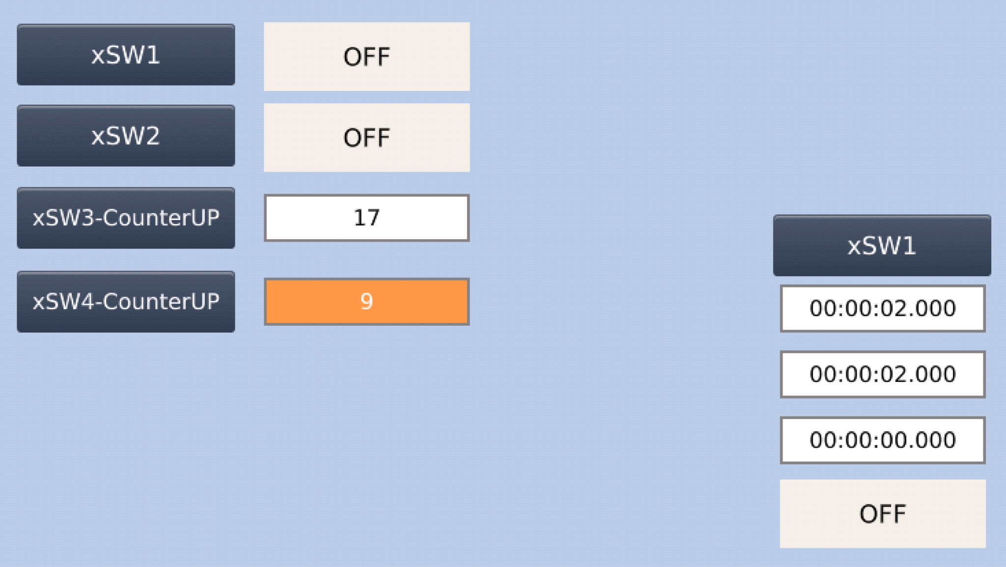
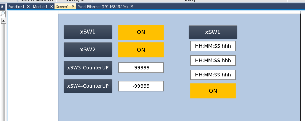
This is the screen we created this time.
Result
Now, let’s actually look at the result. The TimerBox component displays the current value, set value, and accumulated measurement time of the timer variable.
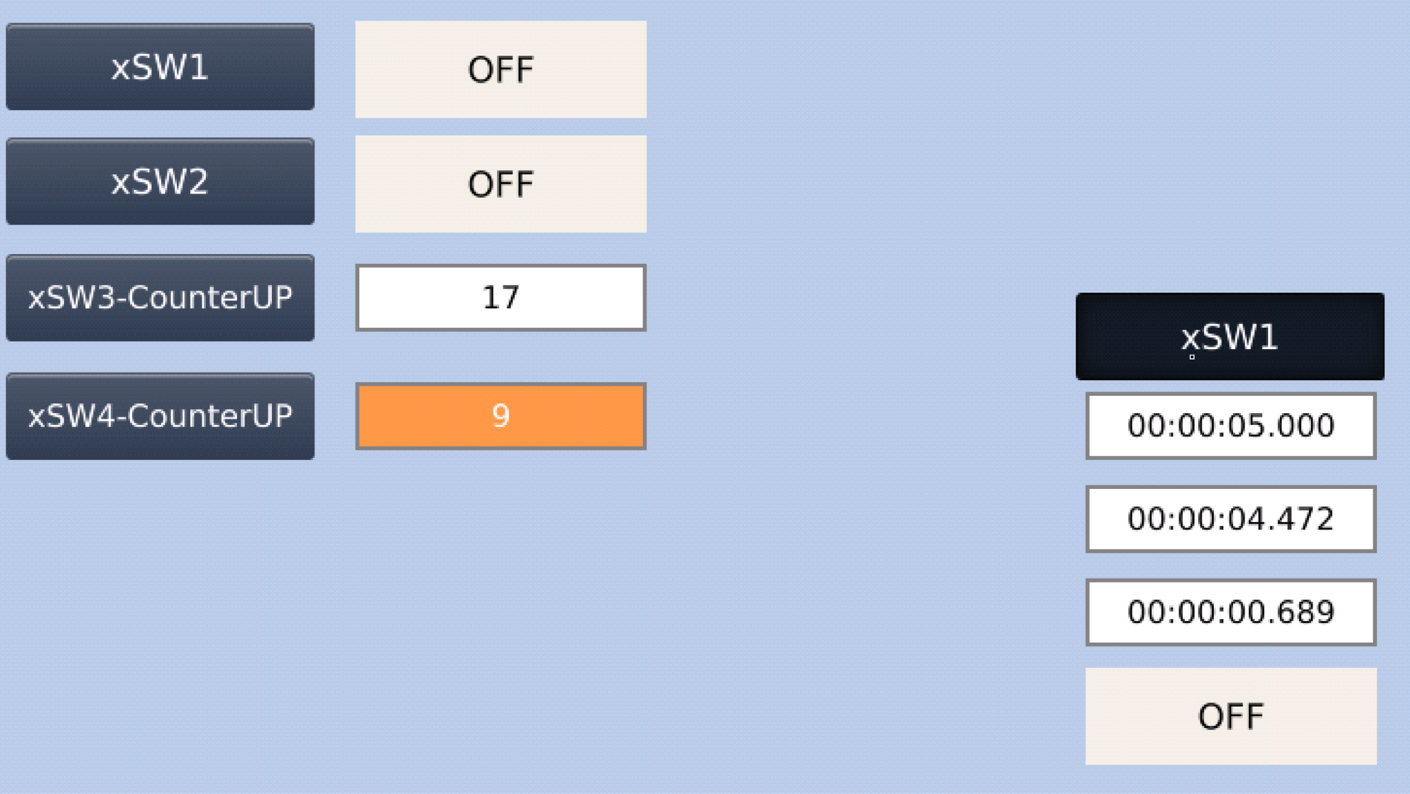
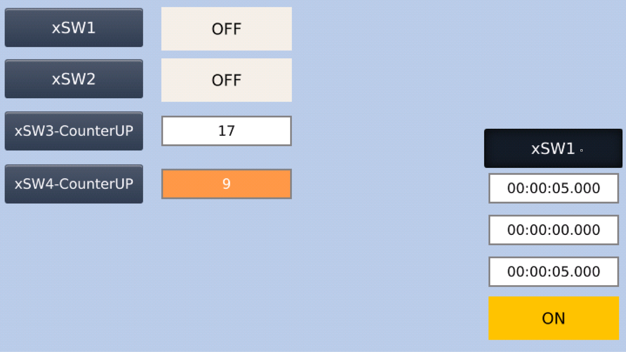
Since the current TIMER set value is 5s, when the time elapses, the TIMER turns ON, and the accumulated measurement time also becomes the same as the set value.
Also, you can change the TIMER’s time setting from the TIMER BOX set in Preset Value.
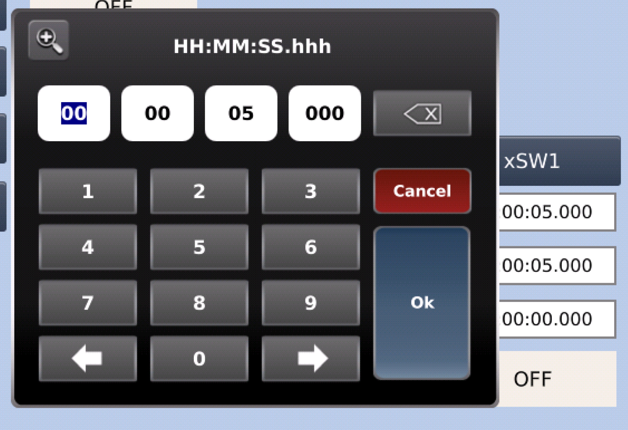
Done! Now the TIMER set value is 2s.