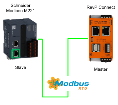
This article I will use Revi Connect and Schneider Modicon M221 to build a Modbus RTU network. Revpi Connect is Master and Schneider Modicon M221 is Slave, and a RS485>USB converter is used in the RevPIConnect.
I will also create an IO Check program on the Schneider side and check the consistency of the data.
Thanks!
The RevPI Connect used in this article was lent by PILZ JAPAN.
PILZ
PILZ supports FA sites as a total solution supplier with safety and automation technology solutions, guaranteeing not only human safety, but also machine and environmental safety, to ensure the safe operation of machines and equipment. Pilz has 42 local companies and branches worldwide and is active in various fields such as packaging, the automotive industry, robotics applications, as well as wind power and railway technology.

Office:
〒222-0033 Kanagawa, Yokohama, Kohoku Ward, Shinyokohama, 3 Chome−17-5 いちご新横浜ビル 4階
HP
Mana Design Works
This article is provided by Mana Design Works. The content of this blog itself is Schneider, but Mana Design Works is an official solution partner of Siemens ,headquartered in Osaka, Japan.Mana Design works can always make optimal proposals for Siemens CPUs, HMIs, drives, motion controllers, and SCADA to domestic manufacturers.

Please get more information from their home page:
Tools
Here is the Converter that I used to convert from USB to RS485.

RevPI Side
Connect it!
Connect the Converter to the USB Port on your RevPI.

Find your ports
Connect the Revpi by using Putty SSH, and use this command to list up all the ports.
| python -m serial.tools.list_ports |
Done!/dev/ttyUSB2 is the USB>RS485 Convertor.
(/dev/ttyUSB0=Port1,/dev/ttyUSB0=Port2,/dev/ttyUSB2=Port3, so our convertor is port3)
| /dev/ttyAMA0 /dev/ttyUSB0 /dev/ttyUSB1 /dev/ttyUSB2 4 ports found |
Check it
We can also confirm the port number by using this command to confirm the port number of your RS485 Converter.
| pi@RevPi8172:~ $ dmesg | grep tty |
Did you see the ch341-uart converter now attached to ttyUSB2 message?This is the usb converter and it is attached to ttyUSB2.
| [ 0.000000] Kernel command line: coherent_pool=4M bcm2708_fb.fbwidth=656 bcm2708_fb.fbheight=416 bcm2708_fb.fbswap=1 smsc95xx.macaddr=B8:27:EB:FF:FD:0E vc_mem.mem_base=0x3ec00000 vc_mem.mem_size=0x40000000 dwc_otg.lpm_enable=0 console=tty1 root=/dev/mmcblk0p2 rootfstype=ext4 elevator=deadline fsck.repair=yes rootwait nosplash plymouth.ignore-serial-consoles [ 0.001422] console [tty1] enabled [ 1.585736] 3f201000.serial: ttyAMA0 at MMIO 0x3f201000 (irq = 81, base_baud = 0) is a PL011 rev2 [ 5.397721] usb 1-1.5.2: FTDI USB Serial Device converter now attached to ttyUSB0 [ 5.401178] usb 1-1.5.3: FTDI USB Serial Device converter now attached to ttyUSB1 [ 10.819530] usb 1-1.2: ch341-uart converter now attached to ttyUSB2 |
Edit CODESYSControl.cfg
Then we need to edit our cfg files.
| nano /etc/CODESYSControl.cfg |
Please insert this line at the end of your file.
| [SysCom] Linux.Devicefile=/dev/ttyUSB |
Edit config.txt
Now we need to edit the config.txt file.
| sudo nano /boot/config.txt |
Insert this line at the end of your file and reset the power.
| enable_uart=1 |
Codesys
Add Modbus COM
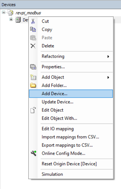
Go to Devices>Add Device.
Go to Modbus>Modbus Serial Port>Modbus COM>Add Devices.
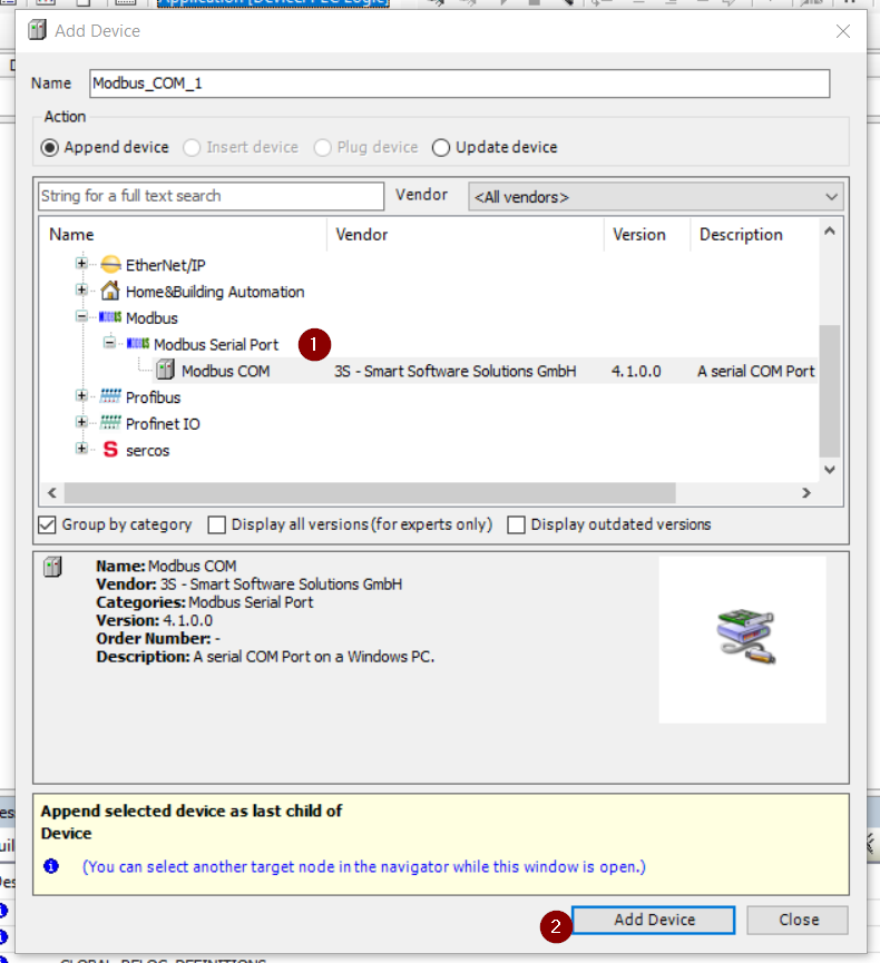
Modbus COM Object is inserted.

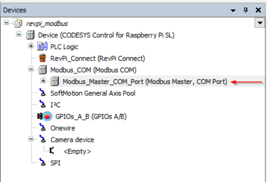
Add Modbus Master
Now we can insert Modbus master into our project.
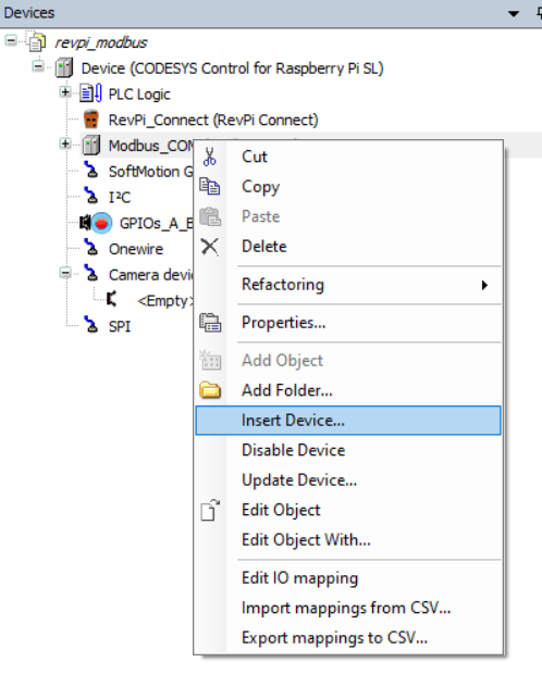
Go to Modbus Serial Master> Modbus Master, COM Port>Add Devices.

Modbus Master is inserted.
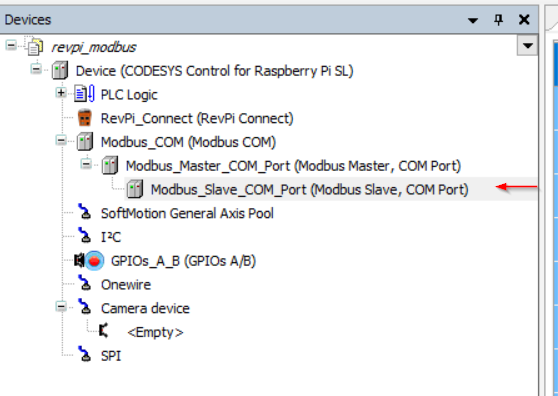
Add Modbus Slave
Finally we can add the Modbus Slave inside the project.

Modbus Slave is inserted.
Program
Now we can create the Program.
GVL
The Status variables of RevPI Connect and Modbus Register Variables are defined in the Global Variable List.
| {attribute ‘qualified_only’} VAR_GLOBAL RevPiStatus :BYTE; RevPiIOCycle :BYTE; RS485ErrorCnt :WORD; Core_Tempature :BYTE; Core_Fequency :BYTE; LED:BYTE; init:BOOL; Unit1_MultipleRegister :ARRAY[0..9]OF WORD; Unit1_ReadingRegister :ARRAY[0..9]OF WORD; END_VAR |
MAIN
In the main program, I will just loopback the output data back to the input data.
| PROGRAM PLC_PRG VAR Status:BYTE; IOCycle:BYTE; RS485_ErroCnt:WORD; Core_Temperature:BYTE; Core_Fequency:BYTE; A1,A2,A3 :INT; B1:BOOL; data1,data2:ARRAY[0..9]OF WORD; END_VAR Status:=GVL.RevPiStatus; IOCycle:=GVl.RevPiIOCycle; RS485_ErroCnt:=GVL.RS485ErrorCnt; Core_Temperature:=GVL.Core_Tempature; Core_Fequency:=GVL.Core_Fequency; data1:=GVL.Unit1_MultipleRegister; data2:=GVL.Unit1_ReadingRegister; GVL.Unit1_MultipleRegister:=GVL.Unit1_ReadingRegister; |
Modbus COM Configuration
Open the Modbus COM Object>configure the Baud rate/Com port in the “General” Tab.

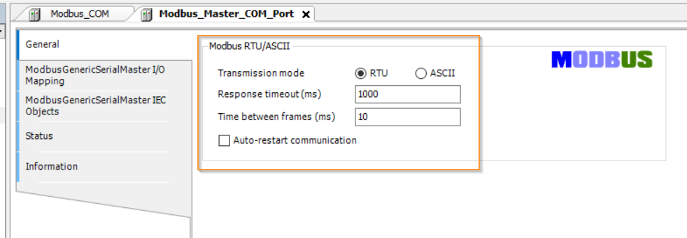
Modbus Master Configuration
Open the Modbus Master Object and setup the Transmission mode to RTU mode and configure your timeout settings.You can also Enable the “Auto-restart communication” options depends on your application.
Modbus Slave Configuration
Open the Modbus RTU Slave >General and setup the slave address and the timeout time.
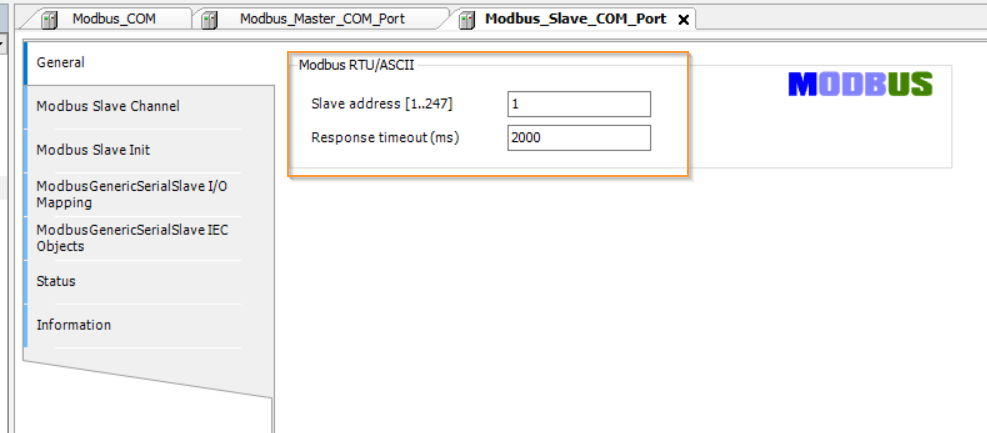
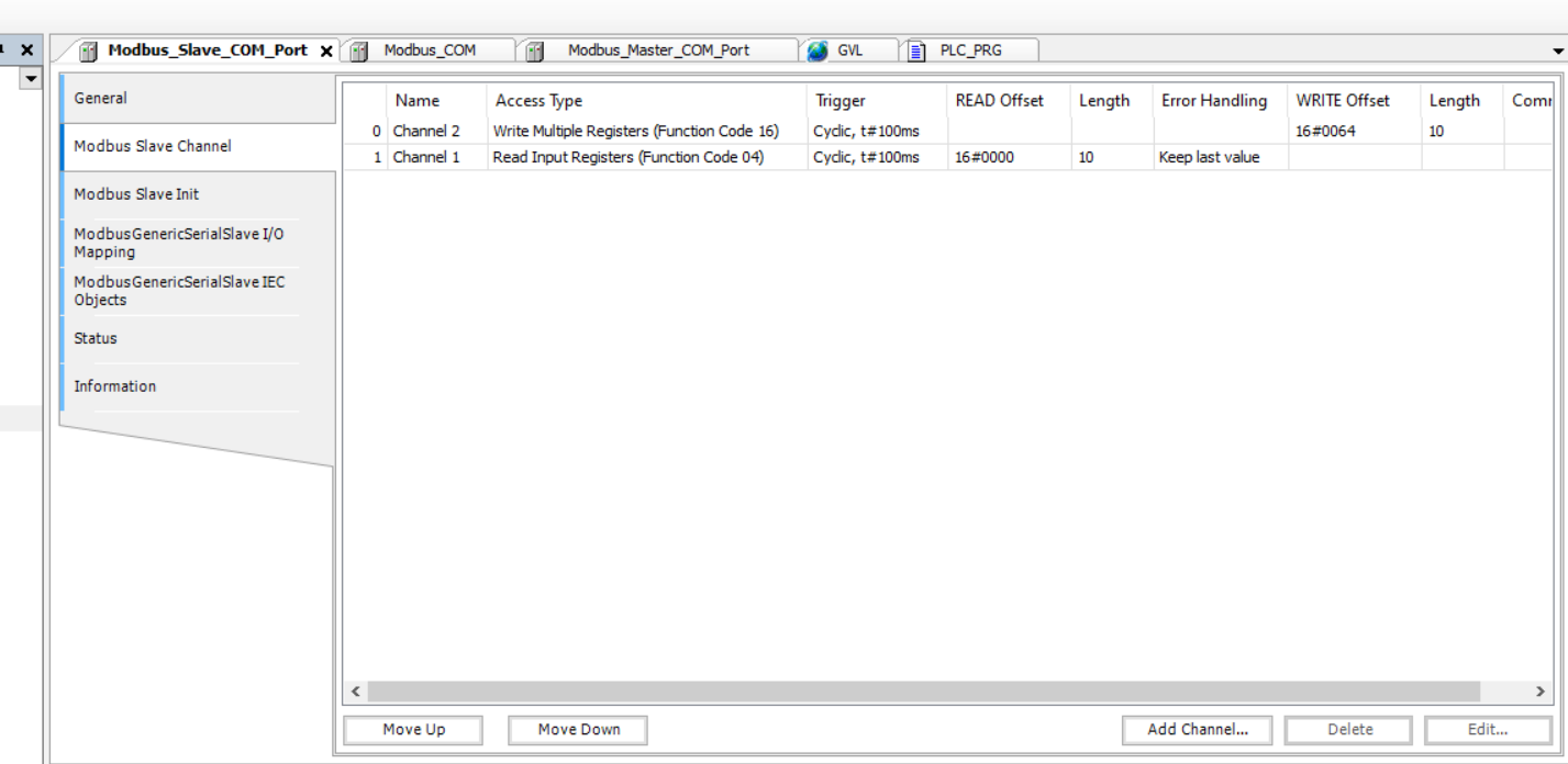
Open the Modus Slave Channel to press to “Add Channel” button to insert your register.
In this tutorial, Function Code=16,Offset=100,10 words and Function Code 04,Offset=0, 10 words are built.
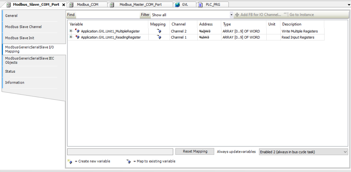
Do not forget to map these variables to your GVL.
Schneider Side
Now we need to configure the Schneider Side.
Connect It!
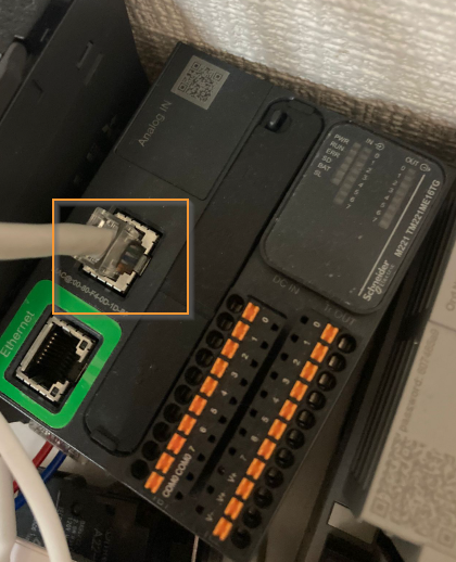
Use a RJ45 Cable and plug it into SL1 Port in TM221.
SL1?
The pin assignment is shown below.
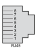
| Pin | RS232 | RS485 |
| 1 | RxD | N.C. |
| 2 | TxD | N.C |
| 3 | RTS | N.C |
| 4 | N.C. | D1 |
| 5 | N.C. | D0 |
| 6 | CTS | N.C. |
| 7 | N.C.* | 5 Vdc |
| 8 | Common | Common |
Wire
Here is the color of the RJ45 connector.

Basic
Configure SL1
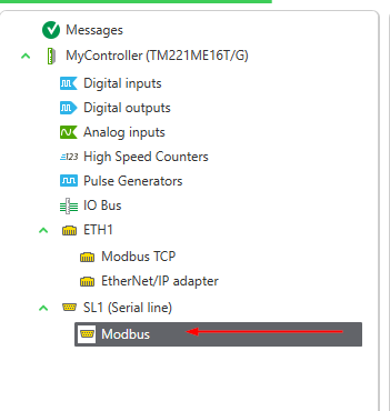
Open the Configuration tab>SL1(Serial line) to configure the serial line port setting.

Choose Modbus as the Protocol, RS485 as the Physical medium and Press “Apply” to save the setting.

Configure Modbus Slave
Go to SL1(Serial Line)>Modbus and configure your Modbus Slave in TM221.
Choose “None” in the Device option>RTU as the Transmission mode.
In the RevPI Connect side, slave number 1 is configured and we need to match it. Please enter “1” here.

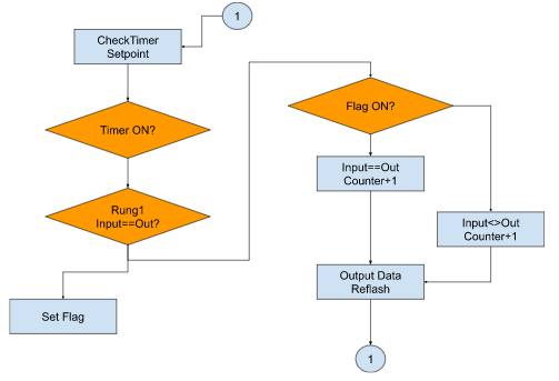
Flow
Here is the Running Flowchart inside Schneider plc.
Programming
Instruction memo – Comparison Block
Here is the compare block that we will use in this tutorial. Choose the Comparison block from the bars.

Drop this Block into Rung.

Comparison block is inserted.
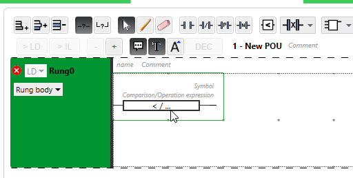
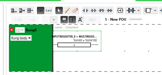
We can directly input the compare expression in the Field.

%MW0=%MW100 is configured in this example, the result will be true if the value of %MW0 and %MW100 are the same.
Mappings
Here is the device list – and shown all devices are used in this tutorial.
Memory Bits
| Address | Symbol | Description |
| %M0 | B_DEVICE_EQ1 | True=The value of INPUT and OUTPUT are same |
| %M1 | B_DEVICE_EQ2 | True=The value of INPUT and OUTPUT are same |
| %M2 | B_DUMMY |
Memory Words
| Address | Symbol | Description |
| %MW0 | INPUTREGISITER_0 | Modbus RTU Register of Schneider PLC output |
| %MW1 | INPUTREGISITER_1 | Modbus RTU Register of Schneider PLC output |
| %MW2 | INPUTREGISITER_2 | Modbus RTU Register of Schneider PLC output |
| %MW3 | INPUTREGISITER_3 | Modbus RTU Register of Schneider PLC output |
| %MW4 | INPUTREGISITER_4 | Modbus RTU Register of Schneider PLC output |
| %MW5 | INPUTREGISITER_5 | Modbus RTU Register of Schneider PLC output |
| %MW6 | INPUTREGISITER_6 | Modbus RTU Register of Schneider PLC output |
| %MW7 | INPUTREGISITER_7 | Modbus RTU Register of Schneider PLC output |
| %MW8 | INPUTREGISITER_8 | Modbus RTU Register of Schneider PLC output |
| %MW9 | INPUTREGISITER_9 | Modbus RTU Register of Schneider PLC output |
| %MW100 | MULTIREGISTER_0 | Modbus RTU Register of Schneider PLC input |
| %MW101 | MULTIREGISTER_1 | Modbus RTU Register of Schneider PLC input |
| %MW102 | MULTIREGISTER_2 | Modbus RTU Register of Schneider PLC input |
| %MW103 | MULTIREGISTER_3 | Modbus RTU Register of Schneider PLC input |
| %MW104 | MULTIREGISTER_4 | Modbus RTU Register of Schneider PLC input |
| %MW105 | MULTIREGISTER_5 | Modbus RTU Register of Schneider PLC input |
| %MW106 | MULTIREGISTER_6 | Modbus RTU Register of Schneider PLC input |
| %MW107 | MULTIREGISTER_7 | Modbus RTU Register of Schneider PLC input |
| %MW108 | MULTIREGISTER_8 | Modbus RTU Register of Schneider PLC input |
| %MW109 | MULTIREGISTER_9 | Modbus RTU Register of Schneider PLC input |
| %MW200 | IODATANOMATCHED_COUNTER | The counter to count how many times of Input and Output data are not coincidences |
| %MW201 | IODATA_MATCHED_COUNTER | The counter to count how many times of Input and Output data are coincidences |
| %MW202 | REFLASHEDTIMER_SETTING | IO data update time. |
Timer
| %TM0 | REFLESHTIMER | Update Timer |
Master Task 1- New POU
Here is the program.
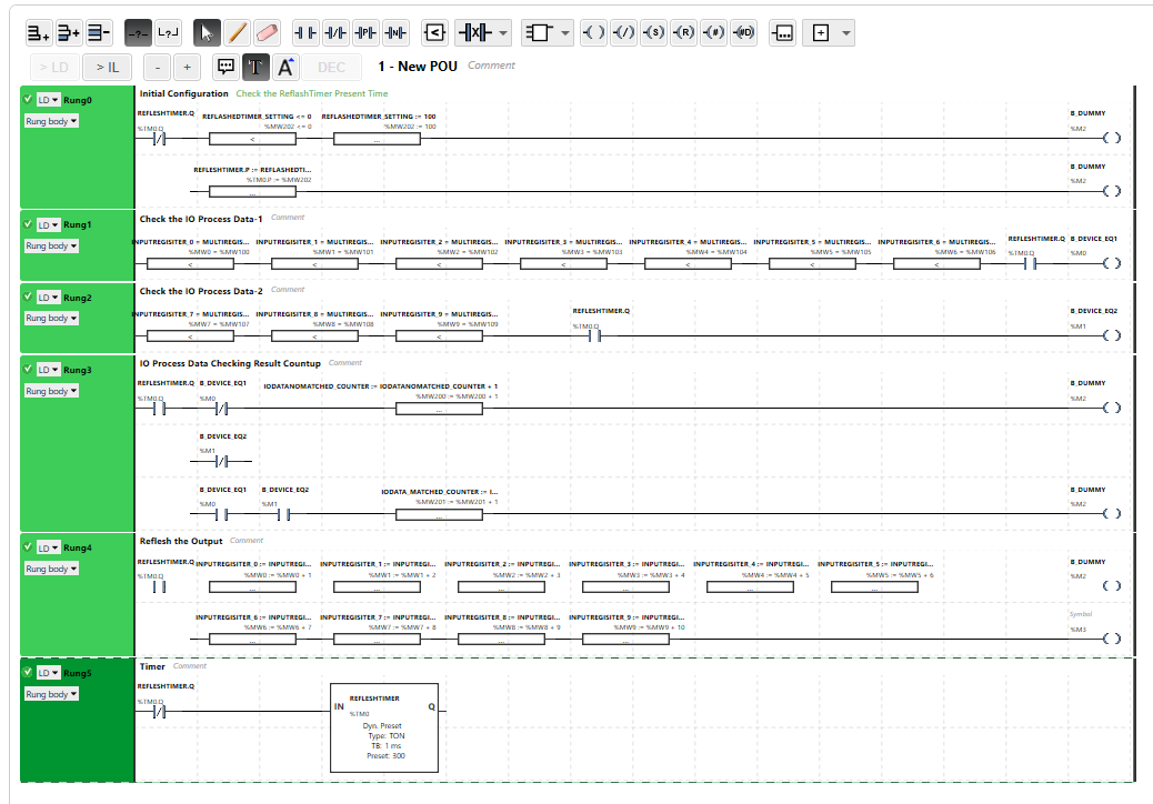
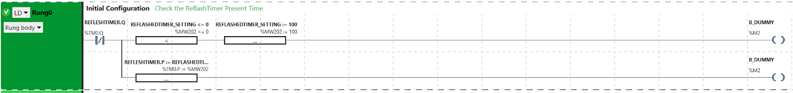
Rung0
A program to configure the Time setting of the Refresh timer.Default value will be overwritten while time settings=0.
Rung1,Rung2
A program to compare the input and output data.

Rung3
These coils will be true depending on the comparison result.

Rung4
update the output data.

Rung5
The Reflesh timer.

Bonus-1 Online Change
We can directly click the Memory word to modify the actual value.
Bonus-2 Dec/Hex Display
The DEC/HEX button can change the Actual Values display format between Hex and Dec.
Bonus-3 Comment Display/Hide
This button can hide/Show your comment.
Bonus-4 Symbol Display/Hide
This button can Show/Hide the Symbol.
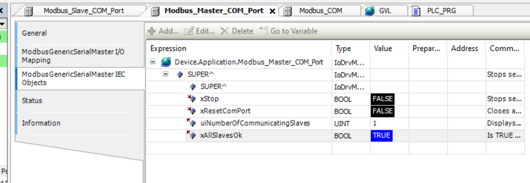
Result
In the Revpi Connect Side, you can see xAllSlaveOK is True – the connection is established.
And the Input is refreshing.

NOCHECK Counter will increase while communication error is happening.
Here is the video to show you the communication status .
Source Code
Please download the source project from this link.
https://github.com/soup01Threes/Codesys/blob/main/RevpiConnect_SchneiderTM221.7z