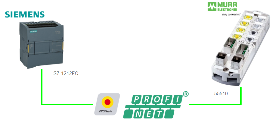
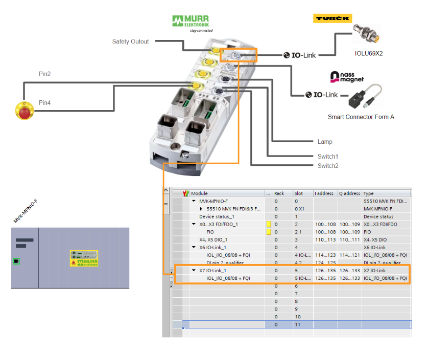
This article describes from scratch how to configure Profisafe/Profinet with Murrelektronik 55510, Profisafe/Profinet IO block with IO-link port. We will also use Turck and Nassmagnet for the IO-link devices.
Let’s start.
Reference Link
Reference Video
Siemens.Using Murrelektronik 55510 Block to configure a Profisafe/Profinet Network
55510?
The 55510 BlockIO from MURRELEKTRONIK used in this article is a high-end module that can support Profisafe and Profinet. This module has the following features:
- PROFINET/PROFIsafe/IO-Link, Small Devices, Metal Version
- US1 to US2 Currently separated supply lines
- PushPull, 5-pin Power Connector
- IRT loop-through in switch
- Supports fast start-up function
- LLDP
- Supports MRP function
- Shared Device function supported
- Supports PROFIenergy function

Layout
This is a Layout for MURRELEKTRONIK’s 55510.
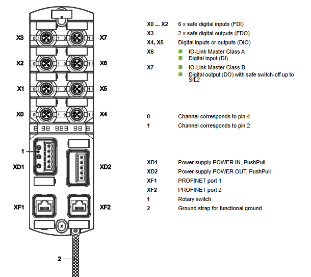
Rotary Switch
MURRELEKTRONIK 55510 has a rotary switch that can be set to Profisafe.

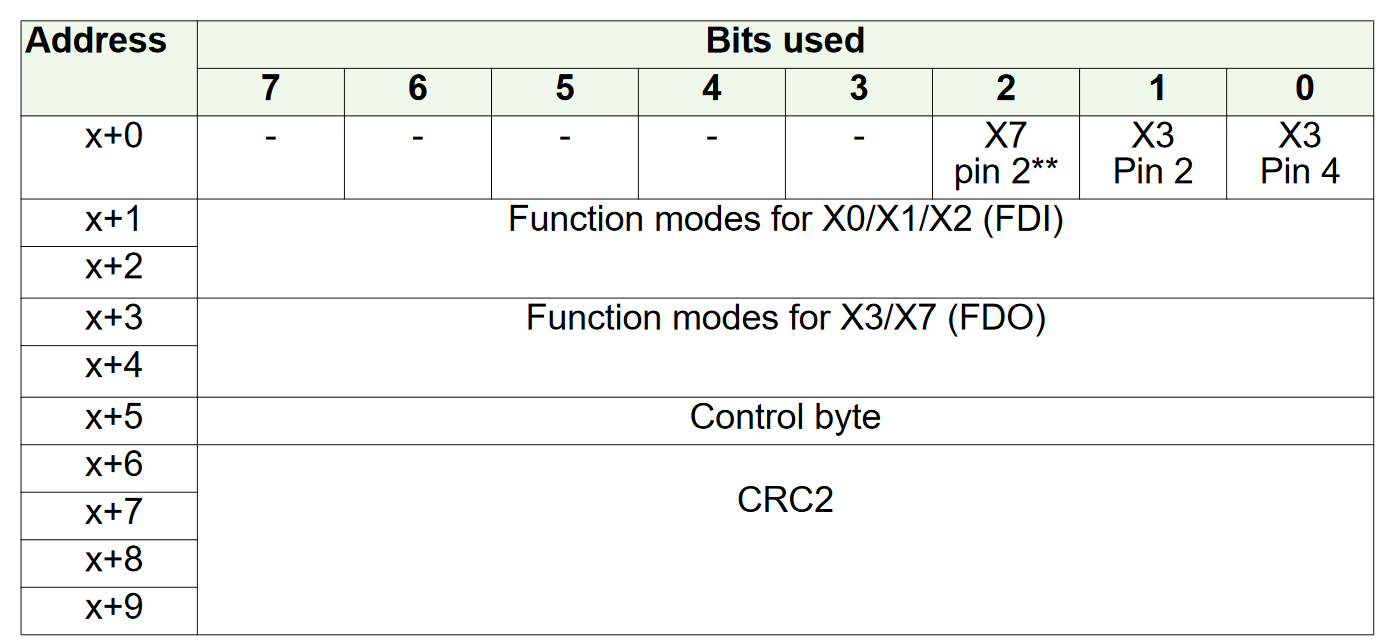
Safety Data Mapping
The next section describes the Mapping of 55510.
INPUT
Here is the safety input data Mapping for X0-X2.

Output
Here is the X3 safety output data Mapping.
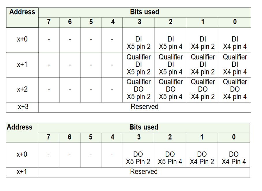
Non-Safety Data Mapping
The IOLINK part is not explained in detail since the only difference is the number of bytes occupied by input/output data.
However, please note that X4 and X5 have different mappings depending on the Port-based or Pin-based settings.
Port based
If Port Based is set, the Mapping for X4 and X5 is as follows.

Pin Based
When Pin Based is set, the Mapping for X4 and X5 is as follows.
How to Config?
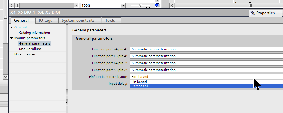
When you select X4/X5 from TIA, there is a Pin/Port based IO Layout item that you can set according to your application.
NASS Smart Connector
This is nassmagnet’s Smart Connector, and the device features:
- M12
- IO-Link V1.1
- PWM control
- Temperature monitoring
- LED color settings
etc..

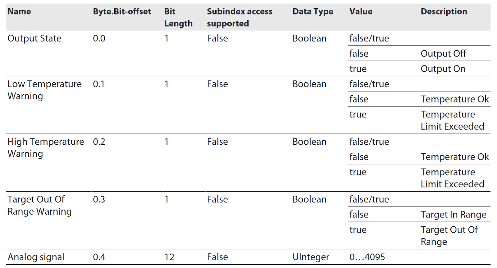
Process Data‐Input
This is the input data Mapp for the NASS Smart Connector.
Process Data‐Output
This is the output data Mapp of the NASS Smart Connector.

Turck IOLU69X2?
Turck’s IOL69X2 is an inductive sensor with analog output and IO-Link communication. The IOL69X2 has following features:
- M12
- IO-Link V1.1
- 12Bit Data 0.2‐3mm
- Temperature Monitoring
- Analog output, 0…10 V (2…10 V parameterizable)
etc..

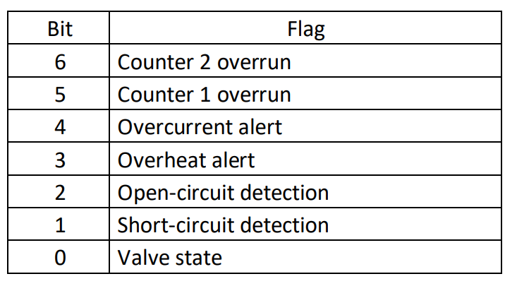
Process Data
This is the input data for IOLU69X2.
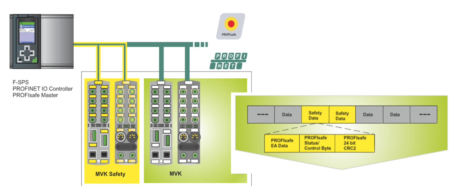
Device in the PROFINET System
The MVK device is both a PROFINET IO device and a PROFIsafe device.
This device is a PROFIsafe device according to the version “PROFIsafe – Profile for Safety Technology on PROFIBUS DP and PROFINET IO”.
The F-Controller processes secure input data and periodically sends secure output data to the PROFIsafe slave. The telegram informs the master/slave about the state of the master/slave and changes the state if necessary.
Shared Device?
The PROFINET IO function allows access to IO devices from two IO controllers.
Advantages?
Shared devices can be used in a system with a Standard Controller and a Fail-Safe Controller.
The Safety SubSlot is assigned to the Safety Controller and the Normal SubSlot is assigned to the Standard Controller. All SubSlots are also assigned to the Safety Controller.

Implementation
MURRELEKTRONIK Side
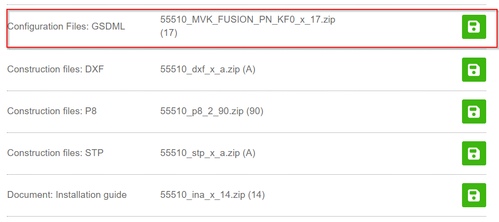
Download GSDML
Download the GSDML File for Murrelektronik’s 55510 MVK IO Blcok from the link below.
Download Safety Configuration Tool
Next, download and install the Safety Configuration tool. This tool calculates the CRC of the MVK IO Block.

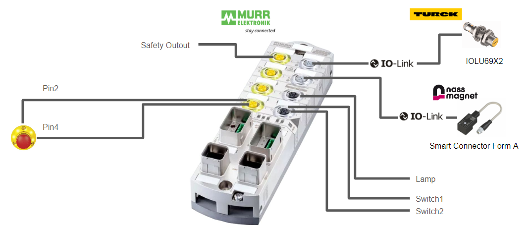
Configuration
Here is the Configuration for this time.
Siemens Side
New Project
Start TIA, Start>Create new project>enter a project name and Create to create a new project.

Click on Project view.
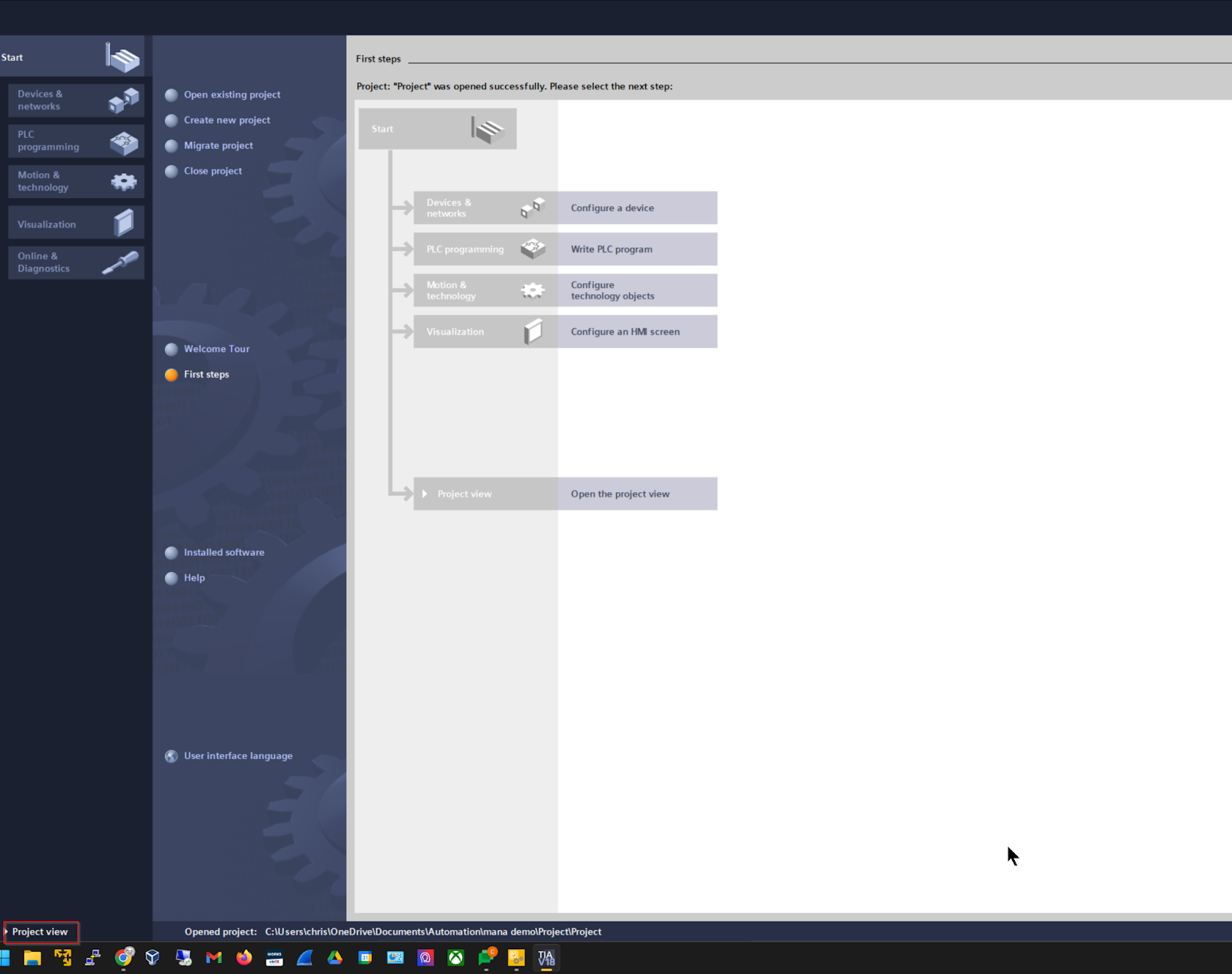
This is the TIA project creation screen.

Add PLC
Let’s add a new Siemens PLC under Project>Add new device.

CPU 1212FC DC/DC/DC will be used for this project, which is compatible with the Profisafe master.

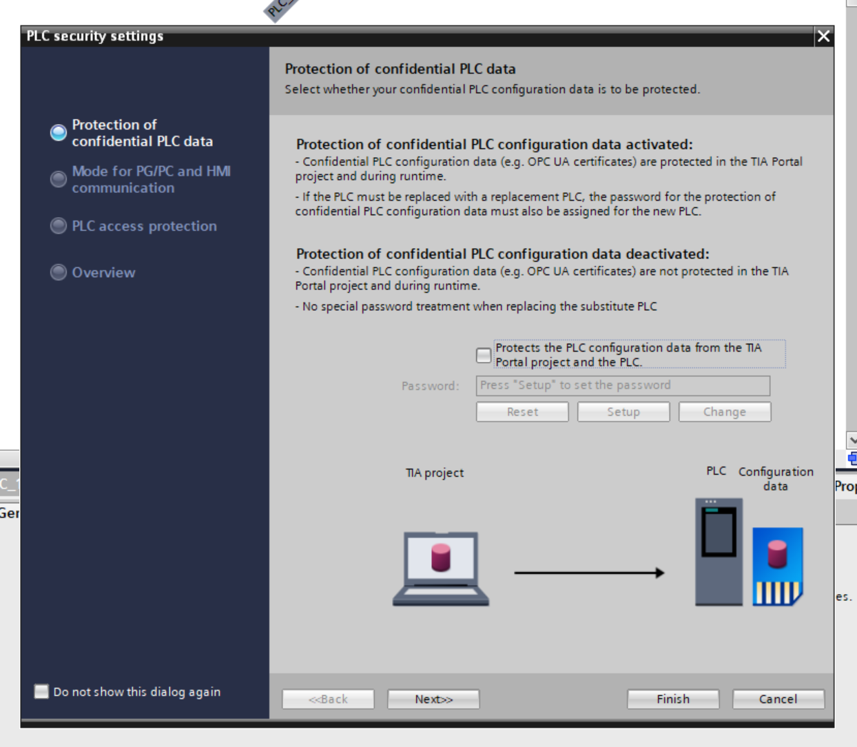
Security Setting
Security settings from TIA V18 regarding the CPU must be preconfigured. Since this is not an actual operation, we will disable all security settings.
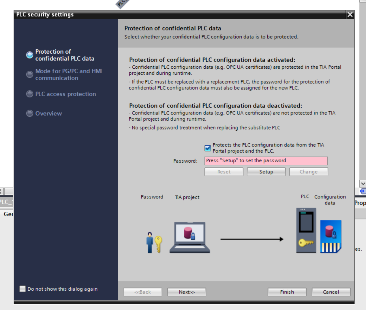
Protects the PLC configuration data from the TIA. Uncheck the “Protects the PLC configuration data from the TIA.
Uncheck the Only allow secure.. Checkbox and press Next>>.

Set to Full access with no password and press Next>> to proceed.

Check again and save the settings with Finish.

Result
Done!S71200 CPU has been added.

IP Configuration
Select CPU>PROFINET interface and set the IP address of the CPU.

Add murrelektronik
The next step is to add murrelektronik’s 55510 IO Block to the Profinet network.

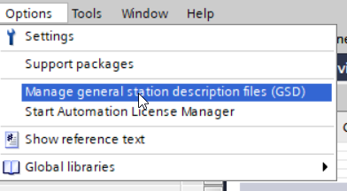
Install GSDML
Click Options>Manage general station description files (GSD).
The GSDML administration screen will appear and click on the … button.
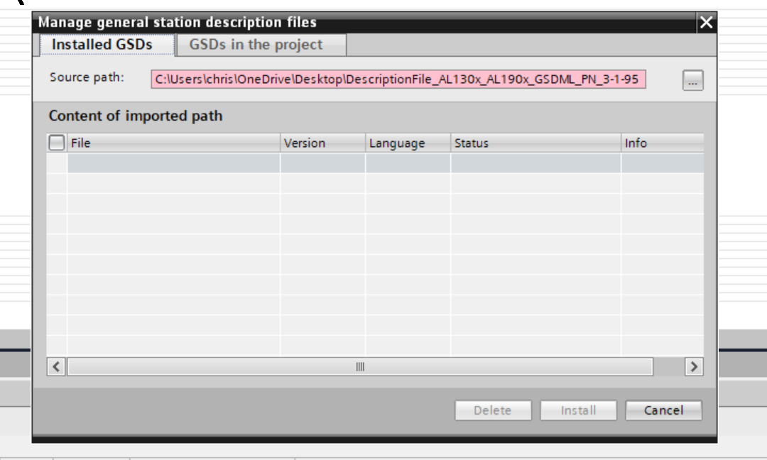
Select the GSDML Folder that was just downloaded.

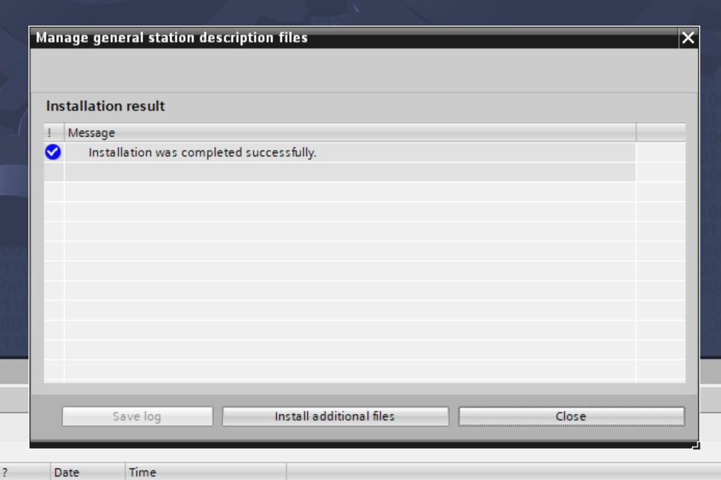
Done!GSDML File is found, install GSDML File with Install.
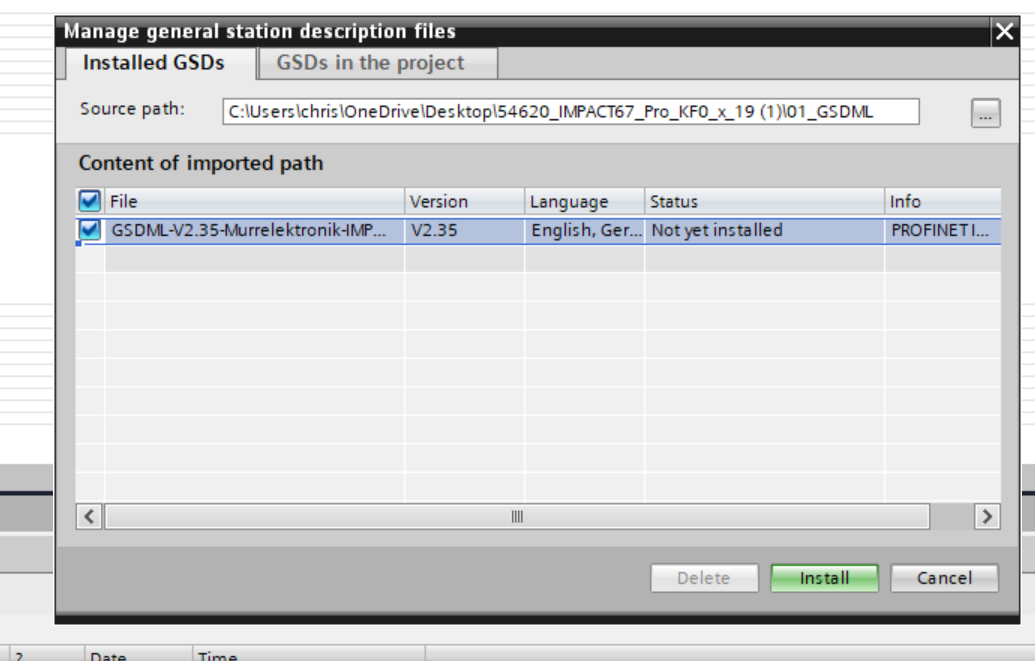
Done!
Add Devices
Search for 55510 from the catalog screen on the right, then 55510 MVK PN… Drop the device in the Network view.

Done!Murreletronik’s 55510 has been added to the Profinet network.

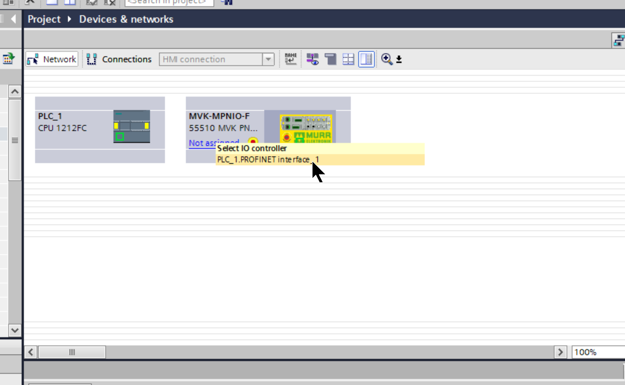
Assign Profinet
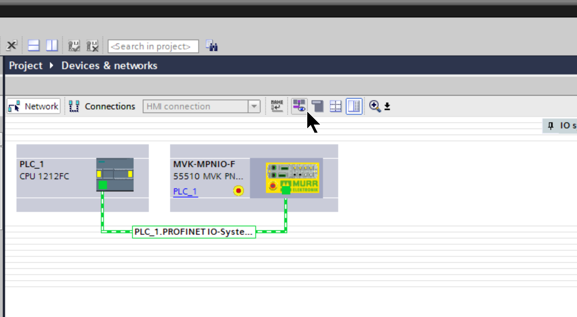
Click on Not assigned and connect Murreletronik’s 55510 IO Block to the Profiet network of CPU S71200.
Done!

Change IP
Now click on the purple eye icon to change the IP address of the Murrelektronik device.
Profinet上にあるすべてのデバイスのIPアドレスが表示されています。

Adjust the IP address to match the application.

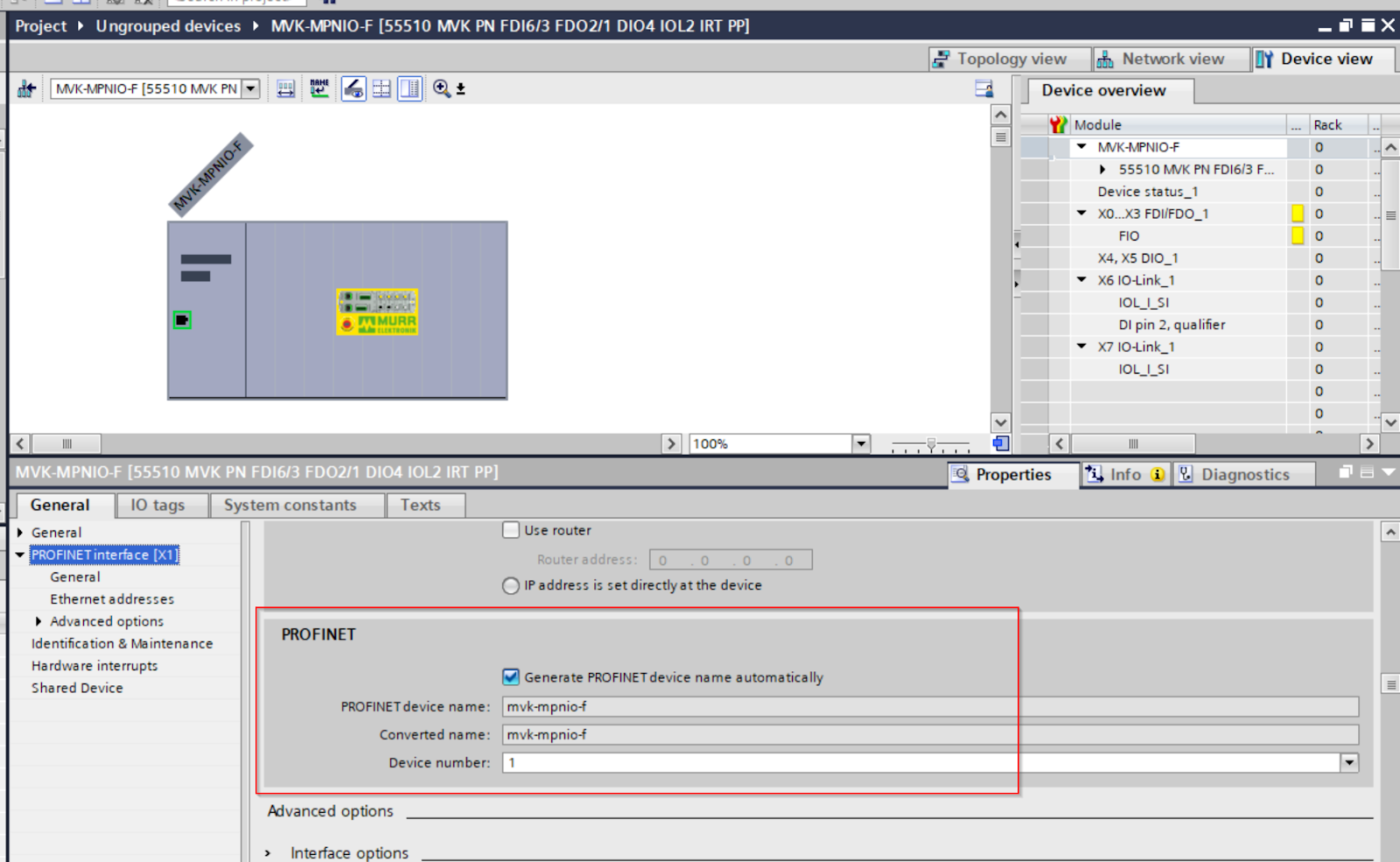
Configure Device Name
Next, change the device name of the Murreletronik IO Block. If you want to change the device name, uncheck the “Generate PROFINET device name automatically” checkbox in the PROFINET section and set the device name according to your application.
Configure Slot
The next step is to set up each Slot.

As shown in the figure below, each Slot can also be changed to suit the application.

X0-X3
X0 to X3 are Ports for safety input/output, so there is no need to change them, but it is more convenient to align I/Q addresses when defining PLC Tags.
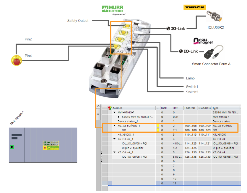
Safety Parameters
The next step is to change the parameters of Profisafe: select Slot2 1 and go to >General>PROFISAFE where you can set the parameters for secure communication.

F_Dest_Addr is the PROFISAFE address of the F-Devices, so it should be set according to the rotary switch setting on the Murreletronik 55510 main unit.

You can also set parameters for the X0-X3 Port in Module Parameters.
In this article, we will enable Test Signal and change the 2 Channel input.

Configure CRC
Safety communication includes a parameter CRC Check, which confirms to the F-HOST side that the parameters of the device currently performing safety communication have not been modified. Also note that if the CRC values of F-HOST and F-Devices do not match, communication cannot be established.
Murreletronik provides a CRC calculation tool for the 55510 IO Block, so right-click on Slot 2 1 > Start device tool to launch the tool.

Start the tool with Start.

Done!Here is the CRC calculation tool from Murreletronik.
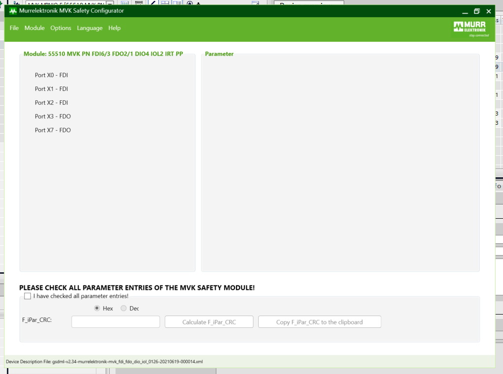
Check the parameter settings for all Ports, put a Checkbox for “I have checked the parameter entries!” and click on the button “Calculate F_iPar_CRC Click the button “Calculate F_iPar_CRC”.

The CRC has been calculated. Change the Display Format to Hex and click on the “Copy F_iPar_CRC to the clipboard” button.

Paste that CRC value into F_iPar_CRC.

X4‐X5
The next step is to set the input/output ports for X4-X5.
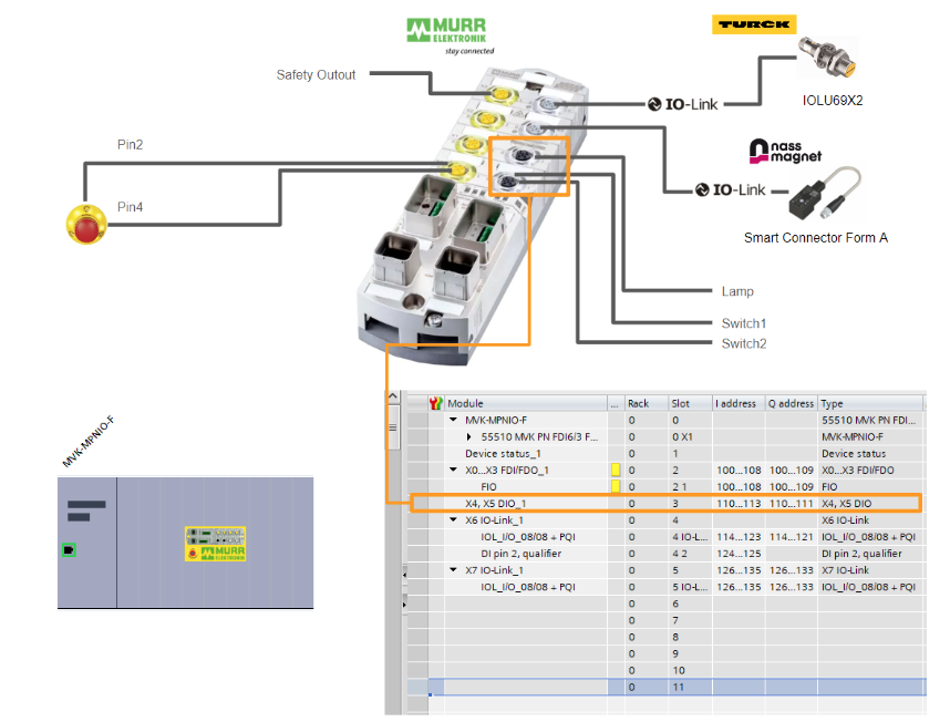
In the Module parameters>General parameters>Pin/port-based IO layout setting item, set the application in the application whether the X4-X5 Mapping will be Port-based or Pin-based.

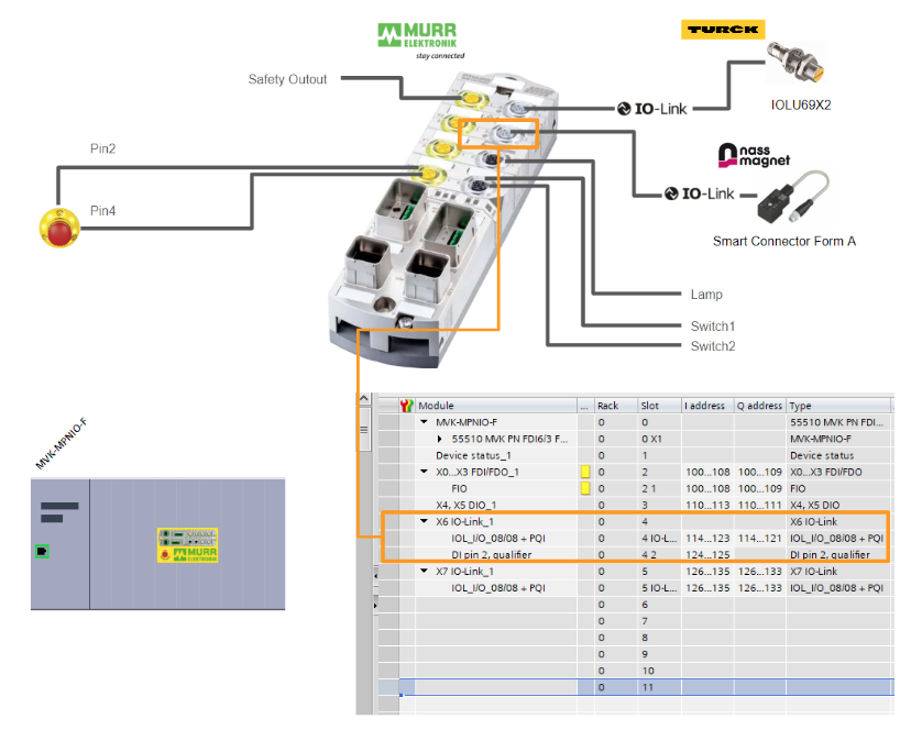
X6
X6 is connected to Nass magnet’s IO Link device Smart Connecotr, so add a Slot for IOL_I/O to X6.
X7
X7 is connected to Turck’s IO Link device IOL69X2, so add a Slot for IOL_I/O to X7.
Program
PLC Data Type
DUT_Murr_55510_SDI_b0
This is the data type of the X0-X2 safety input current value of the Murrelektronik 55510.

DUT_Murr_55510_SDI_b3
This is the data type of the X3 safe output current value of the Murrelektronik 55510.

DUT_Murr_55510_SDIs
This is the data type that summarizes X0 to X2.

DUT_Murr_55510_SDO_b0
This is the X3 safety output command data type.

DUT_Murr_55510_SDOs
This is the data type that summarizes the safety output of the Murreletronik 55510.

DUT_Murr_55510_X4X5_PortBased_b0
This is a structure that summarizes the X4/X5 non-safe input/output data for the Murreletronik 55510.
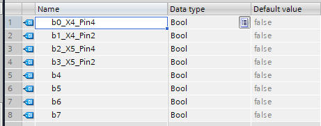
DUT_Murr_55510_X4X5_PortBased_Data
This is a structure that summarizes Murrelektronik 55510 X4/X5 non-safe input/output data to be defined in the DB of the Siemens CPU.

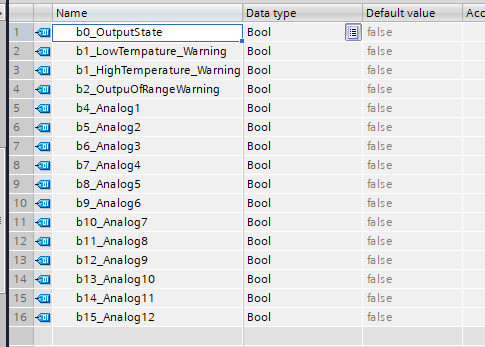
DUT_Nassmagnet_SmartConnector_IN
This is a structure that summarizes the Process Input Data for Nass magnet’s IO Link device, Smart Connector.


DUT_Nassmagnet_SmartConnector_OUT
This is a structure that summarizes the Process Output Data of Nass magnet’s IO Link device, Smart Connector.


DUT_Nassmagnet_SmartConnector_Data
This is a structure that summarizes the Process Input/Output Data for Nass magnet’s IO Link device, Smart Connector.

DUT_TurckIOLU69X2_IN
This is a structure that summarizes the Process Input Data of Turck’s IO Link device IOLU69X2.

DUT_TurckIOLU69X2_Data
This is a structure that summarizes the Process Data (for DB definition) of Turck’s IO Link device IOLU69X2.

PLC Tags
Having completed the configuration of each Port, the next step is to open the PLC Tags Folder to add tags.

Add tags according to the IO address you defined for each Port in Hardware Configuration earlier.

Data Block
Define the DB to be used for the program.
DB_55510
こちらはMurreletronik 55510にある各Portにデータがあります。

DB_SafetyExchange
This is the area where secure data and non-safe data are exchanged.

Function Block
Next, define the Function Block for the Murrelektronik IO-LINK Master and each IO-LINK device.
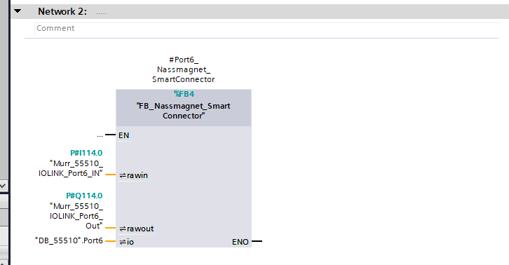
FB_Nassmagnet_SmartConnector
This is a Function Block for Nass magnet’s IO Link device Smart Connector.
Interface
Interface has three Inout parameters, IO-LINK data acquired via Murrelektronik 55510, commands to be sent, and a structure to be compiled into a DB.

NTW2‐5
Network2-5 will be a program that transfers data acquired via IO-LINK to another variable.

NTW6-8
Network6-8 is also a program that transfers data acquired via IO-LINK to another variable.

NTW9-10
Network9-10 will be the commands output to Nass magnet’s Smart Connector.

FB_TurckIOLU69X2
This is a Function Block of Turck’s IO Link device IOLU69X2.
Interface
Interface has two Inout parameters, IO-LINK data acquired via Murrelektronik 55510, and a structure that summarizes the data in a DB.

NTW1-3
Network1-3 will be a program that transfers data acquired via IO-LINK to another variable.

NTW4-5
Network4-5はTurckのIO-LINKデバイスから計測した距離値を0.2-3mmにScalingします。

FB_55510
Here is the Function Block of the Murrelektronik 55510, which calls the FBs defined earlier according to the devices installed on each Port.
Interface
Define the Instance required to use the Function Block of Turck-Nass Magnet.

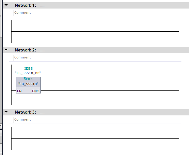
NTW1
This is a Function Block for the Turck IOLINK device IOLU69X2.

NTW2
This is the Function Block for the Smart Connector of the Nass Magnet IOLINK device.
NTW3
This is the reset button signal to be sent to the Safety Function Block.

NTW4
This is a program to control the lamp output of X4.

Main_Safety_RTG1
最後は安全プログラムを作成します。
Interface
Interface has an Instance of Function Block for emergency stop and global reset.

NTW1
This is a program that uses the Siemens standard Safety Function Block in ETSOP1 to control emergency stop.

NTW2
This is a Safety Function Block that resets the Profisafe module.

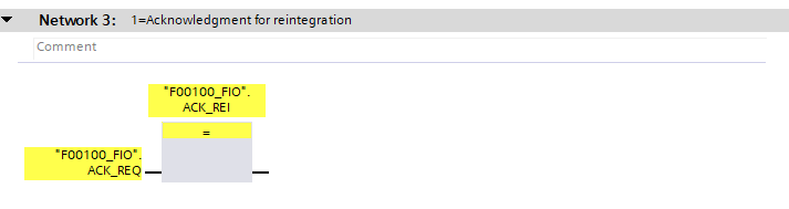
NTW3
This is a program to reset 55510.
OB1
Finally, call Function Block with OB1.
Download
Download the Hardware Configuration and program to the CPU.
Result
Done! Profinet and Profisafe communication between Siemens S7 1212FC and 55510 has been established.


Next, check the status of the IOLINK device from MURRELEKTRONIK’s Devices Tools.

Done!55510 is found.

Right-click on the appropriate device>Assign.

Done! The device has been Uploaded to the project. Next, click the Go Online button.

Proceed with Yes.

Next, Check Device checks the IOLINK Port against the connected devices.
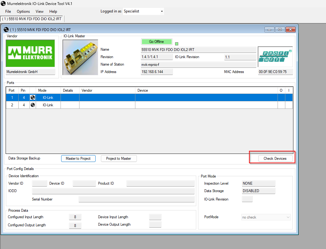
Done!Click “Take devices into Engineering” to upload devices to the project.

Done!

IOLink devices on each port were also properly recognized.


You can see the operation of MURRELEKTRONIK 55510 safety IO in this video.
Murrelektronik.MVK PN FDI6/3 FDO2/1 DIO4 IOL2 IRT PP Safety IO Operation
You can see how the MURRELEKTRONIK 55510 and Turck IOLINK devices work together in this video.
Murrelektronik.MVK PN FDI6/3 FDO2/1 DIO4 IOL2 IRT PP IOLink with Turck IOLU69X2
You can see how the MURRELEKTRONIK 55510 and the Nassmagnet IOLINK device work together in this video.
Murrelektronik.MVK PN FDI6/3 FDO2/1 DIO4 IOL2 IRT PP IOLink with Nassmagnet SmartConnector
Download
Download the project from this link.
https://github.com/soup01Threes/Siemens/blob/main/ProjectMurr-55510-en.zap18