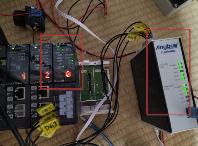
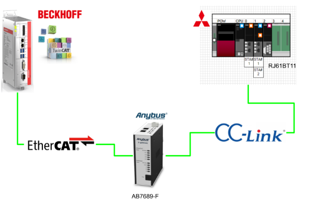
This article describes the start-up of the AB7689-F CC-Link Slave/EtherCAT Slave Gateway from HMS.For CC-LINK Master it is IQ-R’s RJ61BT11 and for EtherCAT Master it is Beckhoff TwinCAT3.
Let’s get started.
Reference Link
AB7689-F?
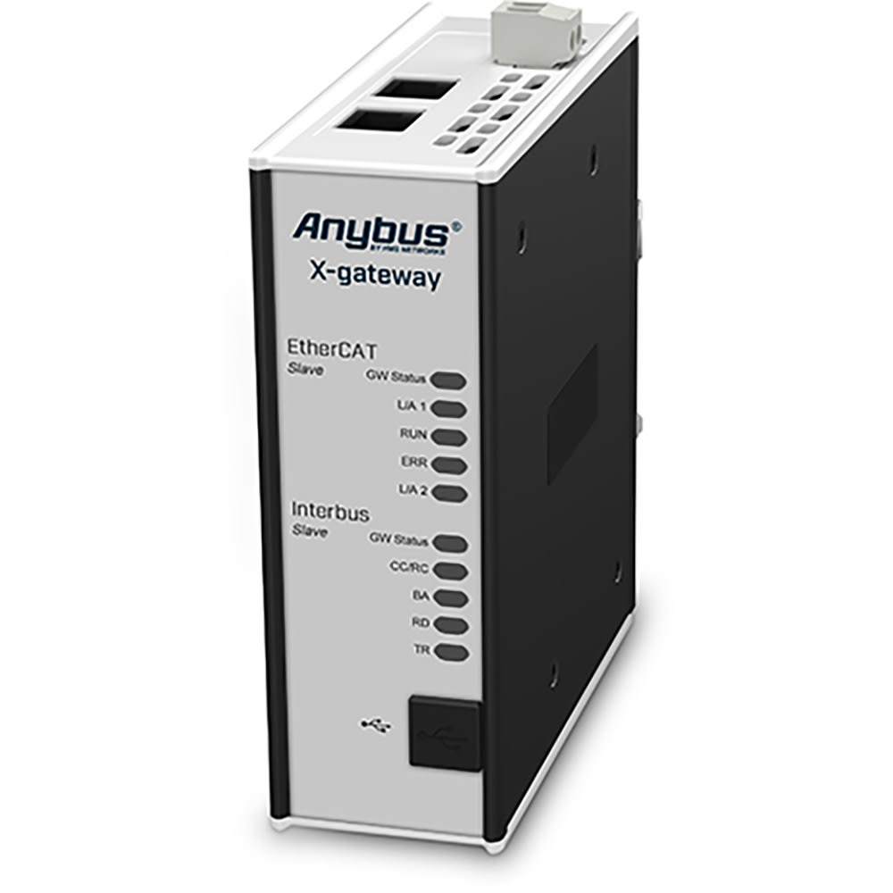
The AB7689-F is a Gateway that can connect EtherCAT systems with CC-Link systems.The Anybus gateway ensures reliable, secure and fast data transfer between different industrial networks.
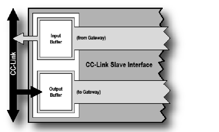
CC-Link Slave Interface
The CC-Link slave interface for X-gateway implements an electrically isolated CC-Link interface. This interface operates as a slave device and can therefore be accessed by the CC-Link master, but does not initiate communication itself.
Data is exchanged via two buffers as follows:
- Input Buffer
This buffer holds data transferred from other networks, i.e. data that can be read by the CC-Link master. - Output Buffer
This buffer is transferred to the other network, i.e. the CC-Link master, for writable data.
Features
The CC-Link Slave side has the function shown in the diagram below.
- On-board configuration switches
- Supports CC-Link v1 and v2
- Up to 8 extension cycles
- Up to 128 I/O points (bits) in each direction, 16 I/O words (16 bits) (CC-Link v1)
- Up to 896 I/O points (bits) in each direction, 128 I/O words (16 bits) (CC-Link v2)
- Supports baud rates from 156 kbps to 10 Mbps
- Transparent CC-Link communication (standard mode)
- PLC profile compliant communication (PLC profile mode)
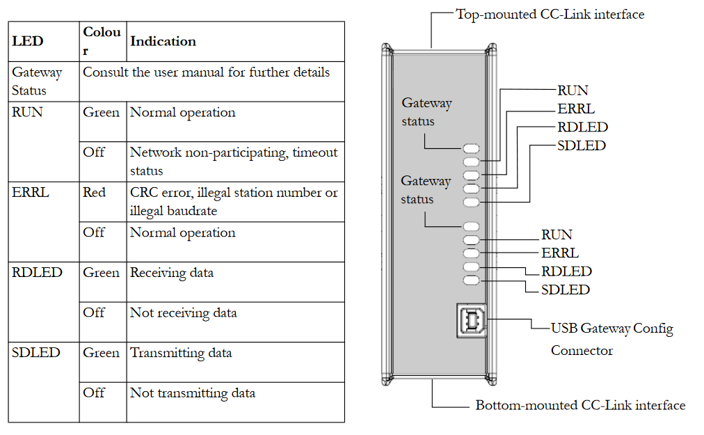
Status LED
This is the LED status on the CC-Link Slave side.
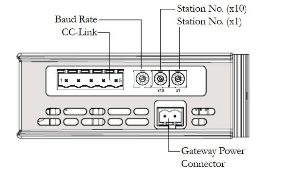
Connectors & Switches
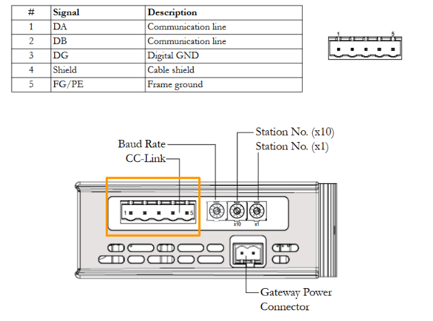
This is the CC-Link Slave configuration switch and Connector diagram.
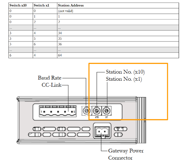
Station No.
Stations can be set from 1-64.
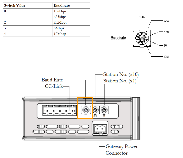
Baud Rate
The baud rate can be set via a switch as follows.
CC-Link Connector
This is the CC-Link Connector arrangement.
EtherCAT Slave
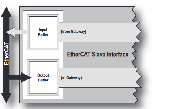
The EtherCAT slave interface for the Anybus X-gateway implements CANopen on EtherCAT and exchanges up to 512 bytes of data in each direction.
The interface acts as a slave node. This means that it can be accessed by the EtherCAT master, but does not initiate communication itself.
The interface exchanges data through two buffers as follows:
- Input Buffer
This buffer holds data transferred from other networks, i.e. data that can be read by the Ether-CAT master. - Output Buffer
This buffer is data that is transferred to other networks and is writable by the EtherCAT master.
Features
The following functions are available on the EtherCAT Slave side.
- CANopen over EtherCAT
- Up to 512 bytes of cyclic data (PDO) in each direction
- Up to 512 bytes of acyclic data (SDO) in each direction
Status LED
This is the LED status on the EtherCAT Slave side.
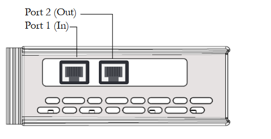
Connectors and Switches
This is the Port of the EtherCAT Slave.
Mapping
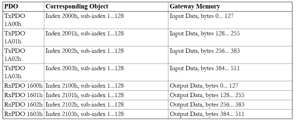
Implementation
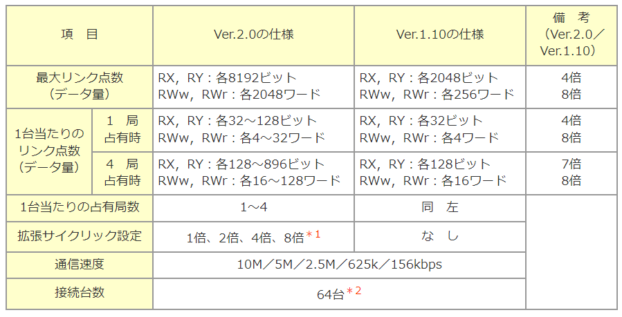
CC-Link Map
These are the specifications for CC-Link V1.10 and V2,0.
https://www.mgco.jp/magazine/plan/mame/b_network/0502/
Anybus Side
Let’ s Build from the HMS Gateway side.
Install Tools
Download the Anybus Configurator Manager and Anybus Transport Provider from the links below.
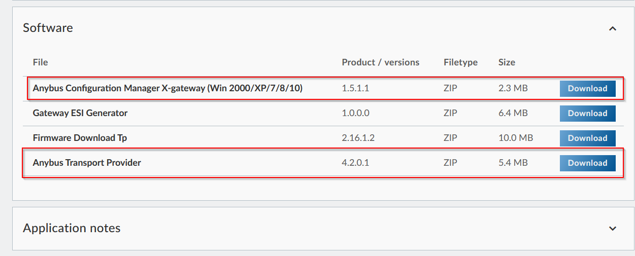
Tool-Installation Anybus Transport Provider
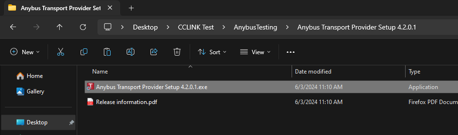
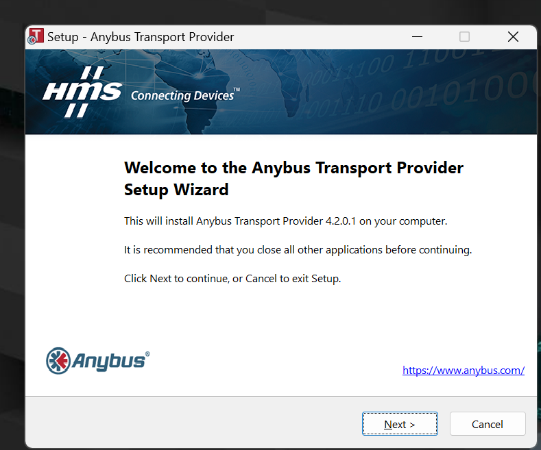
Before installing the Anybus Configurator, install the Anybus Transport Provider here.
Proceed with Next>.
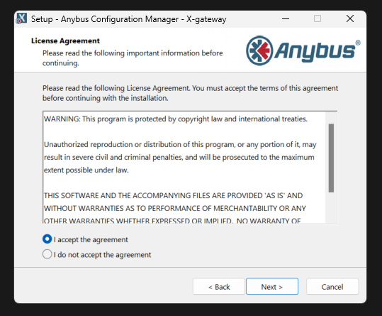
Agree to the licence and proceed with Next>.
Set the Location to install and proceed with Next>.
Start installation.
Please wait a moment.
The USB Driver should also be installed.
Done!
Tool- Installation Any bus Configuration Manager
Next, install the Any bus Configuration Manager from HMS.
Proceed with Next>.
Agree to the licence and proceed with Next>.
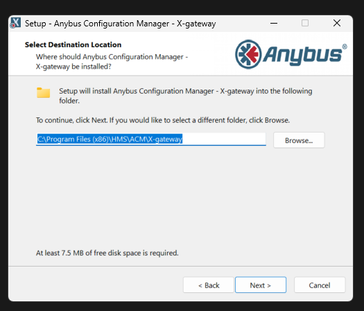
Set the Location to install and proceed with Next>.
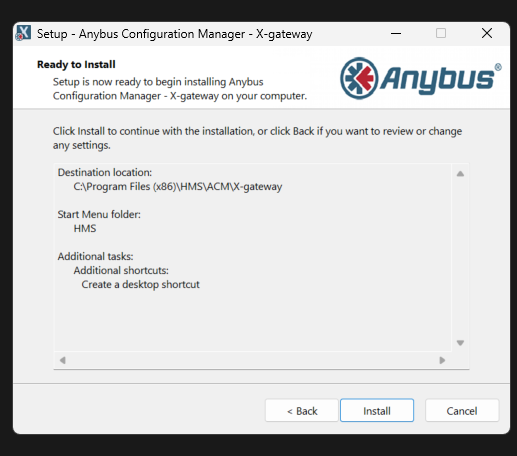
Proceed with Next>.
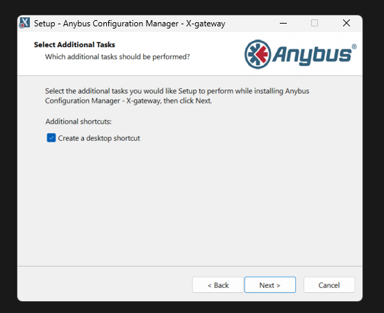
Create Shortcut and proceed with Next>.
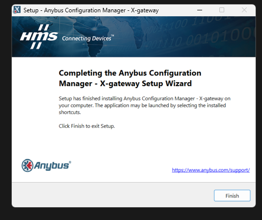
Start installation.
Done!
Configuration
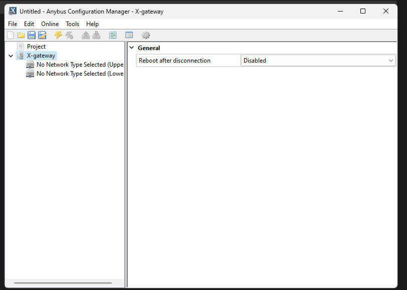
Start the Anybus Gateway and configure the Gateway.
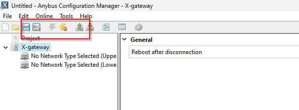
This is the Any bus Configuration Manager screen.
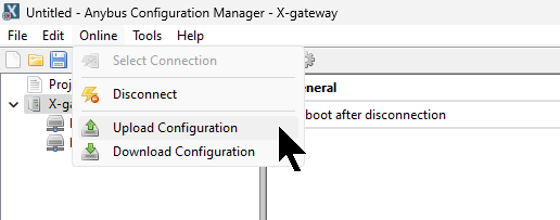
Select Connection
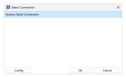
Online>Select Connection to set the connection interface between the PC and the module.
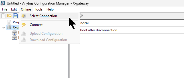
Select USB connection and confirm with >Ok.
Connect
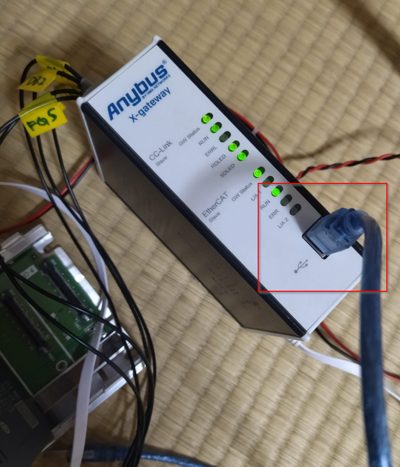
Connect the USB Port on the module itself to the PC.
Connect your PC to the module via Online>Connect.
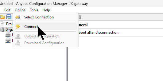
Done!
Upload Configuration
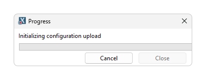
Upload your module’s configuration under Online>Upload Configuration.
Please wait a moment…
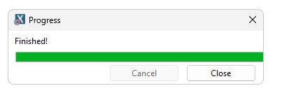
Done!
The Any bus Configuration Manager shows CC-Link Slave and EtherCAT Slave.

Configure-CC-Link Side
Configure the CC-Link side.
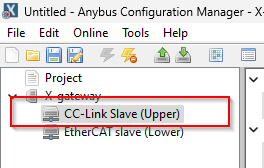
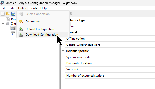
This time, We configure the CC-Link slave with 4 stations, Version 1 and Standard System Mode settings.
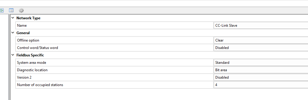
Configure-EtherCAT Side
Next, configure the EtherCAT Slave side: set the Input PDO and Output PDO to a maximum of 512 Bytes.
Download Configuration
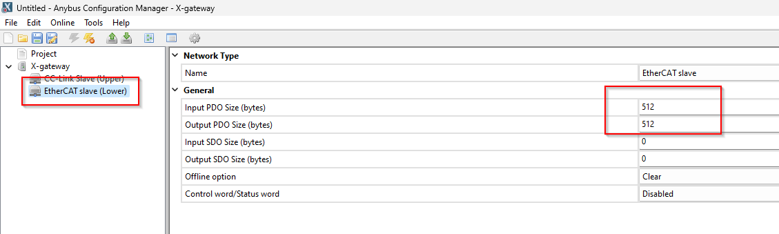
Finally, use Online>Download Configuration to download the configuration to the module.
Please wait a moment…
Done!
GXWorks3 Side
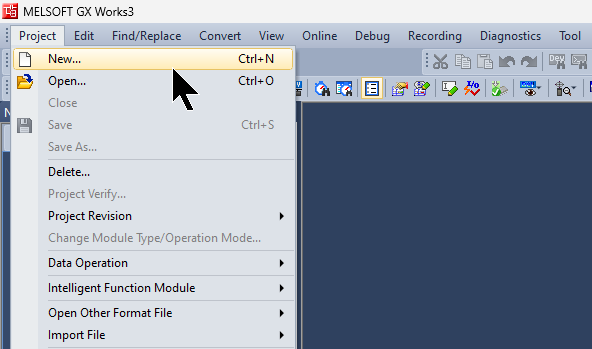
New Project
Start GXWorks3 and start a new project with Project>New.
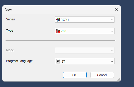
Select the RCPU used in this article and proceed with Ok.
Done!A new project has been created.

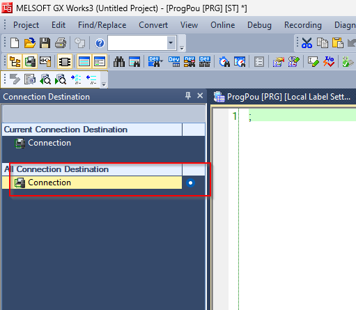
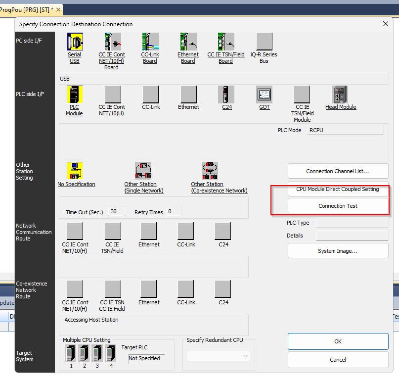
Check Connection
The next step is to set up the connection between the PC and the CPU.
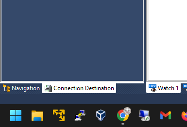
Click on Connection.
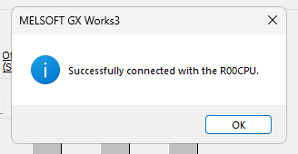
Check the USB connection with Connection Test.
Done!
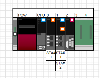
Module Configuration
The next step is to configure Hardware Configuration in Module Configuration.
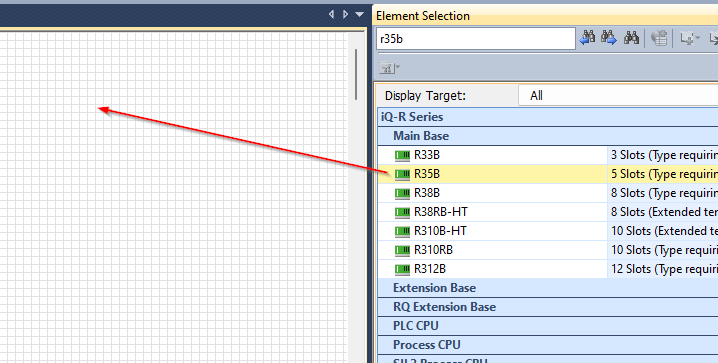
There are only RCPUs on Default.
R35B
Add R35B Slots Module.
Done!
Install CPU
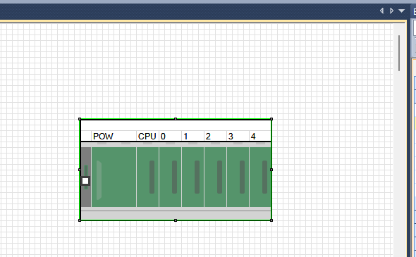
The next step is to move the R00CPU to the CPU.
Done!CPU Slot has been set.
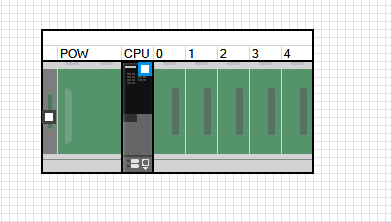
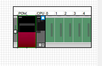
R61P
Next, add the power supply module R61P.
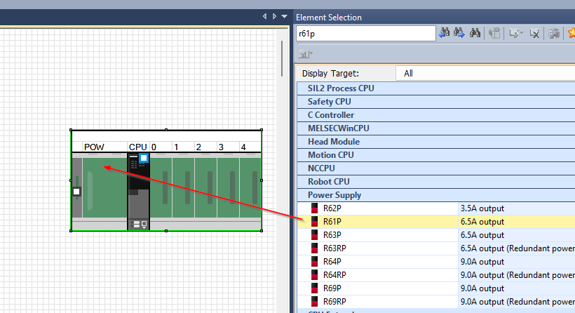
Done!
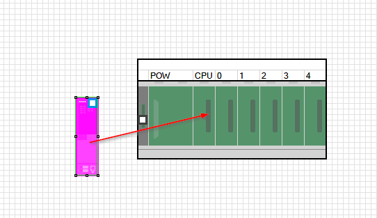
Add RJ61BT11
The last step is to add the CC-Link module RJ61BT11, which is used in this article.
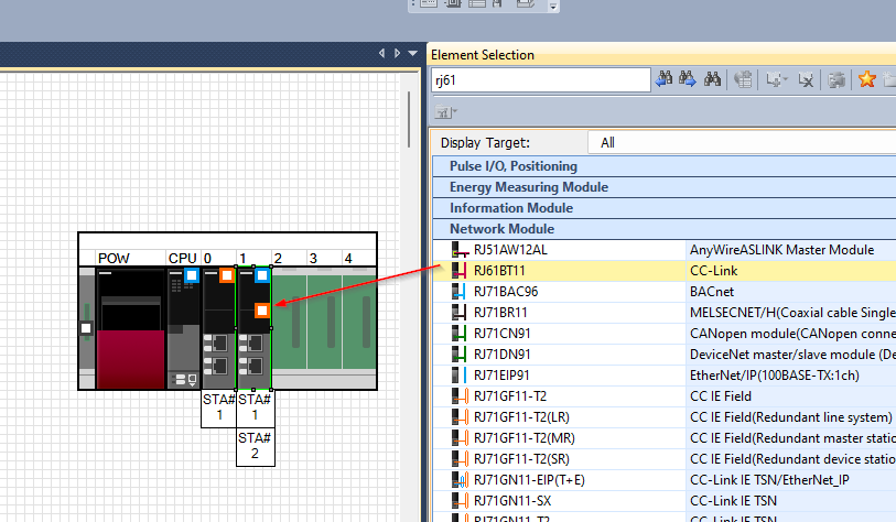
Done!
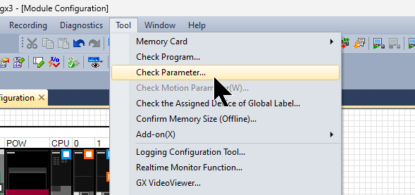
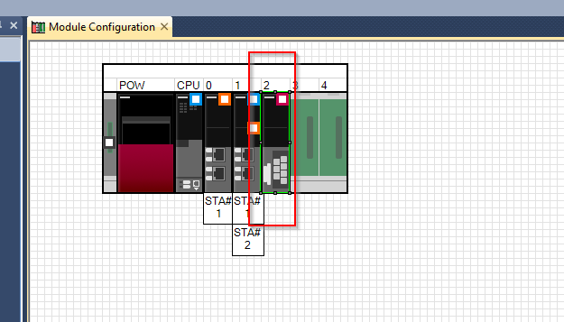
Check Parameter
Check the parameters of the module under Tools>Check Parameter.
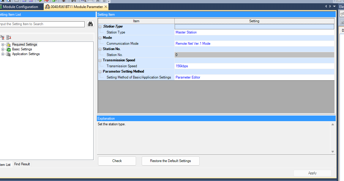
Configure RJ61BT11
Now open the RJ61BT11 and configure the module settings.
This is the RJ61BT11 configuration screen.
Network Configuration
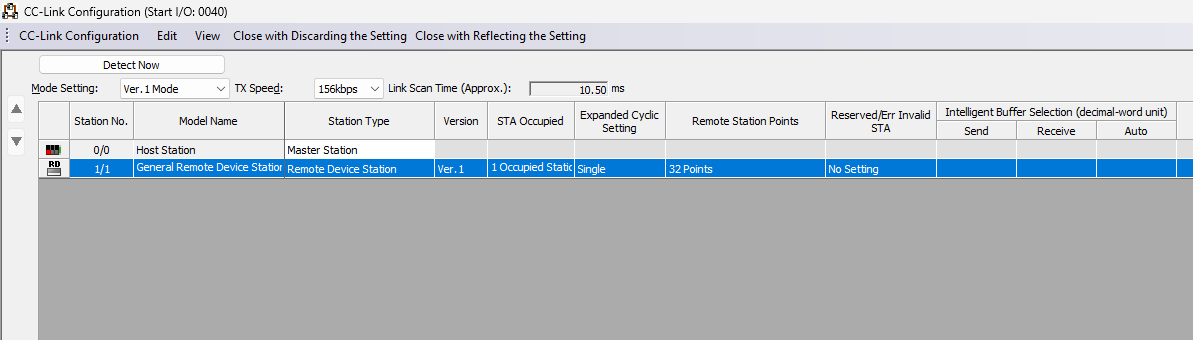
Go to Basic Setup>Network Configuration Setup>CC-Link Configuration.
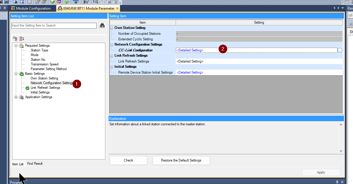
The CC-Link Configuration screen appears.
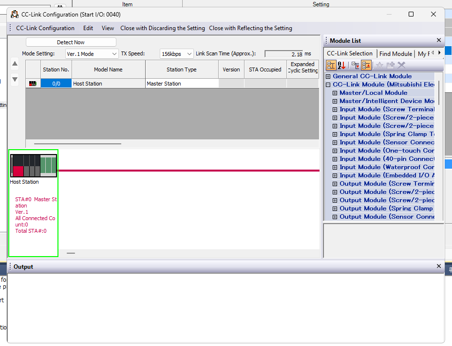
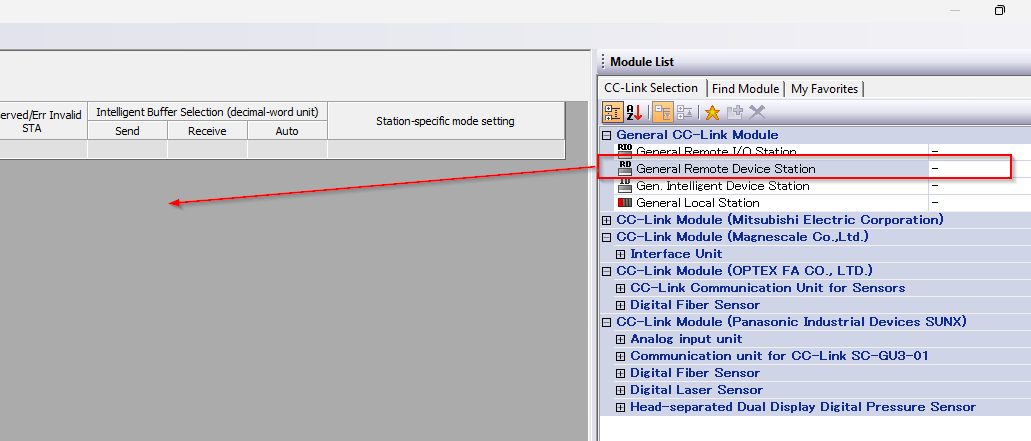
General CC-Link Module>General Remote Device Station is added to the network.
Done!
Set Version to 1 and STA Occupied to 4.
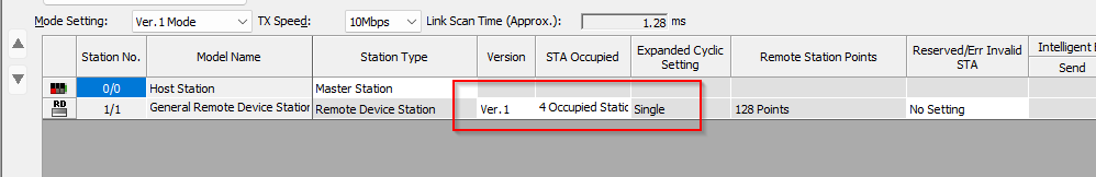
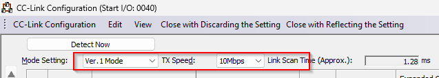
Set Mode Setting to Ver.1 Mode and Tx Speed to 10 Mbps.
Save the configuration under CC-Link Configuration>Close with Reflecting the Setting.
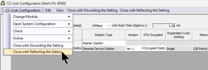
Check the parameters with the Check button and save your settings with Apply.
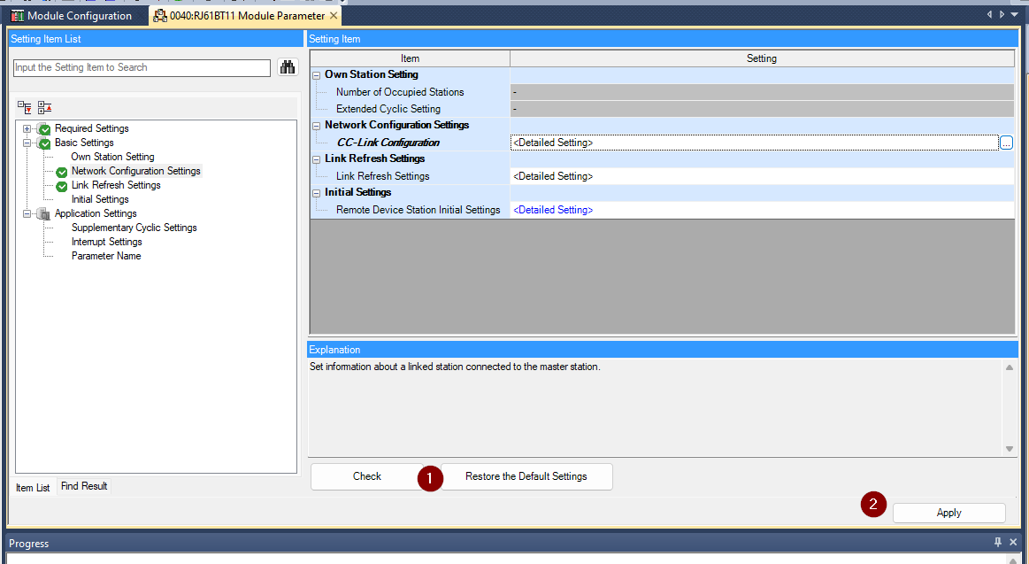
Reflesh Setting
Next, click on Link Reflesh Settings to configure the IO data update settings.
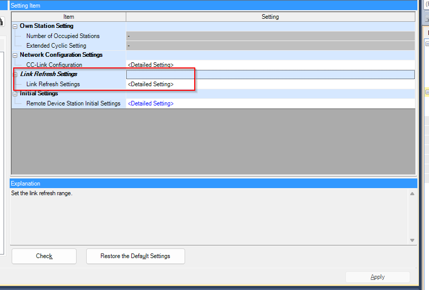
Set up the four stations according to the settings as shown in the diagram below.
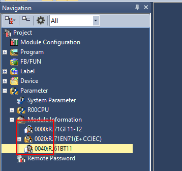
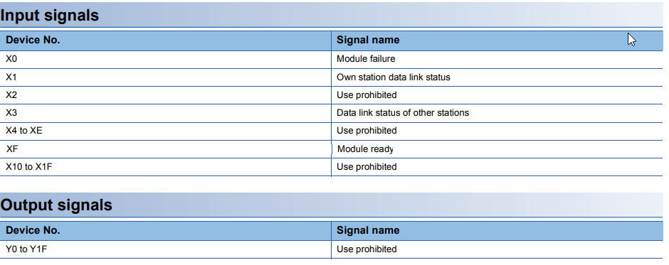
Module IO
Next, check the module IO of the RJ61BT11: Module Information>0040:RJ61BT11 is displayed and the module IO of the RJ61BT11 starts with XY40.
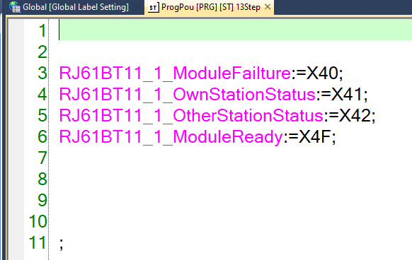
Program
The last step is to create a simple program for the communication test.
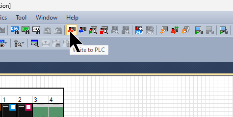
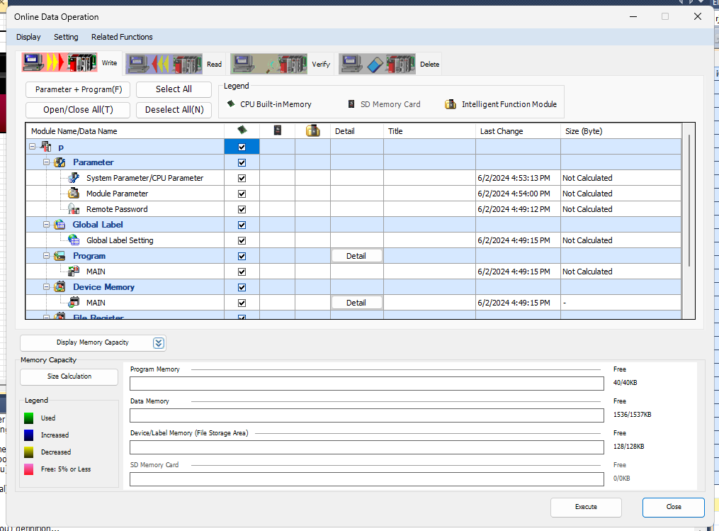
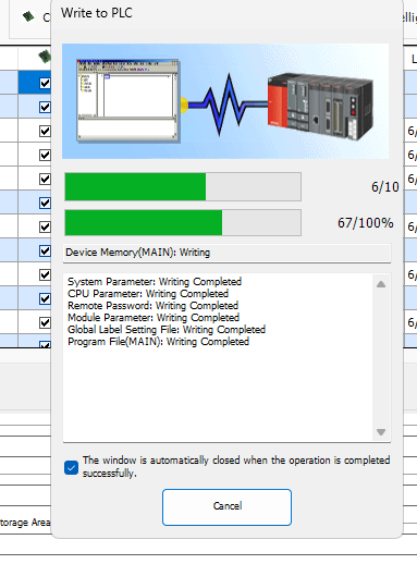
Downlaod to PLC
Download your project to the CPU with Write to PLC.
Start downloading your project with Execute.
Please wait a moment…
TwinCAT3 Side
The last step is to set up the TwinCAT3 side.
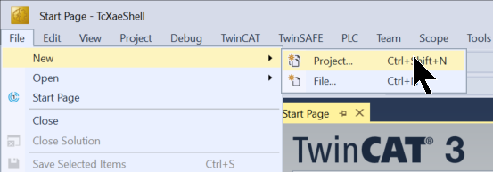
New Project
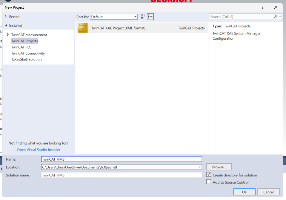
Create a new TwinCAT3 project at File>New>Project.
Select TwinCAT XAE Project > OK to proceed.
Install ESI
Download the ESI File at the following Link.
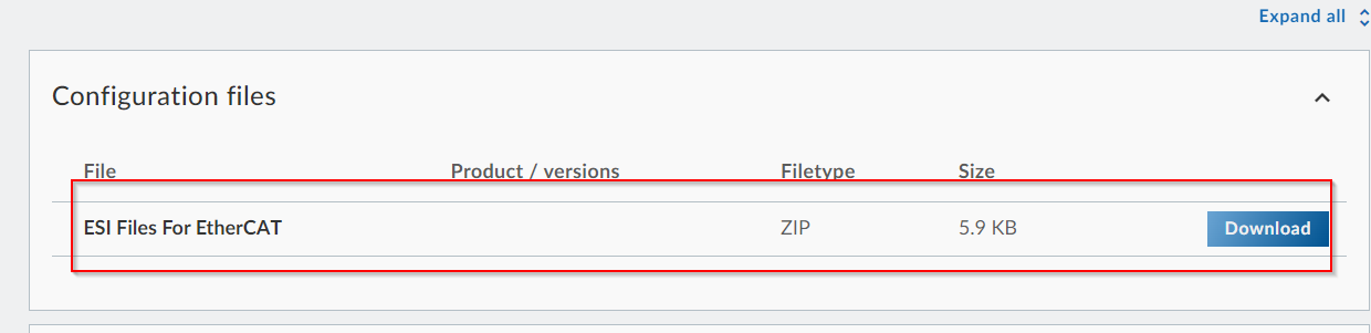
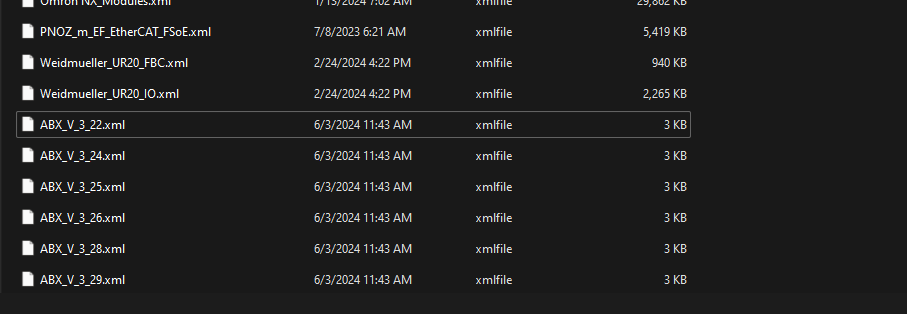
Store the ESI File in the following Path.
C:\TwinCAT\3.1\Config\Io\EtherCAT
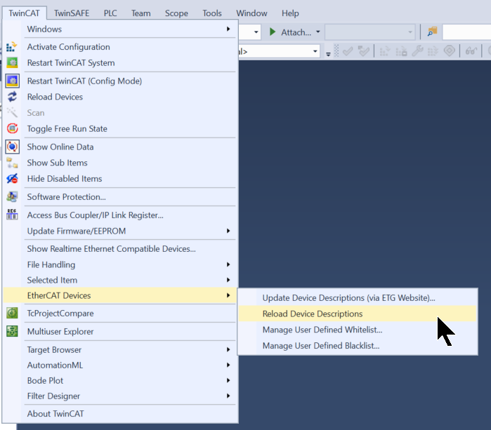
Reload the EtherCAT Slave File in TwinCAT>EtherCAT Devices>Reload Device Description.
Add EtherCAT Master
To add an EtherCAT Master, click on I/O>Devices>Add New Item.
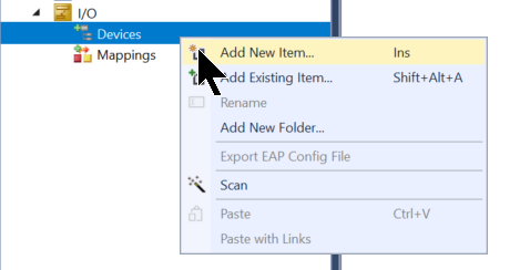
Add EtherCAT>EtherCAT Master.
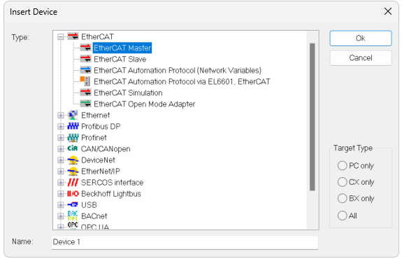
Done!
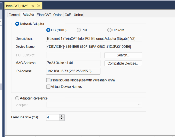
Configure the EtherCAT Driver used by the IPC.
Scan Network
Search for EtherCAT Slaves using the TwinCAT3 AutoScan function.
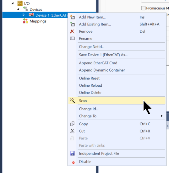
Done!Anybus Gateway found.
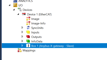
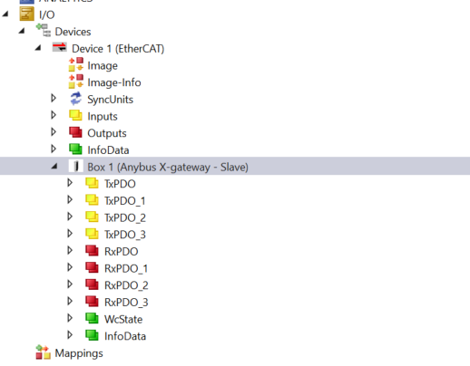
As you have just set up 512 Bytes of input/output data in the Any bus Configuration Manager, the same is reflected in the Tab of Process Data.
This was reflected in both TxPDO and RxPDO.
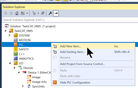
Add PLC
To add a PLC, go to PLC>Add New Item.
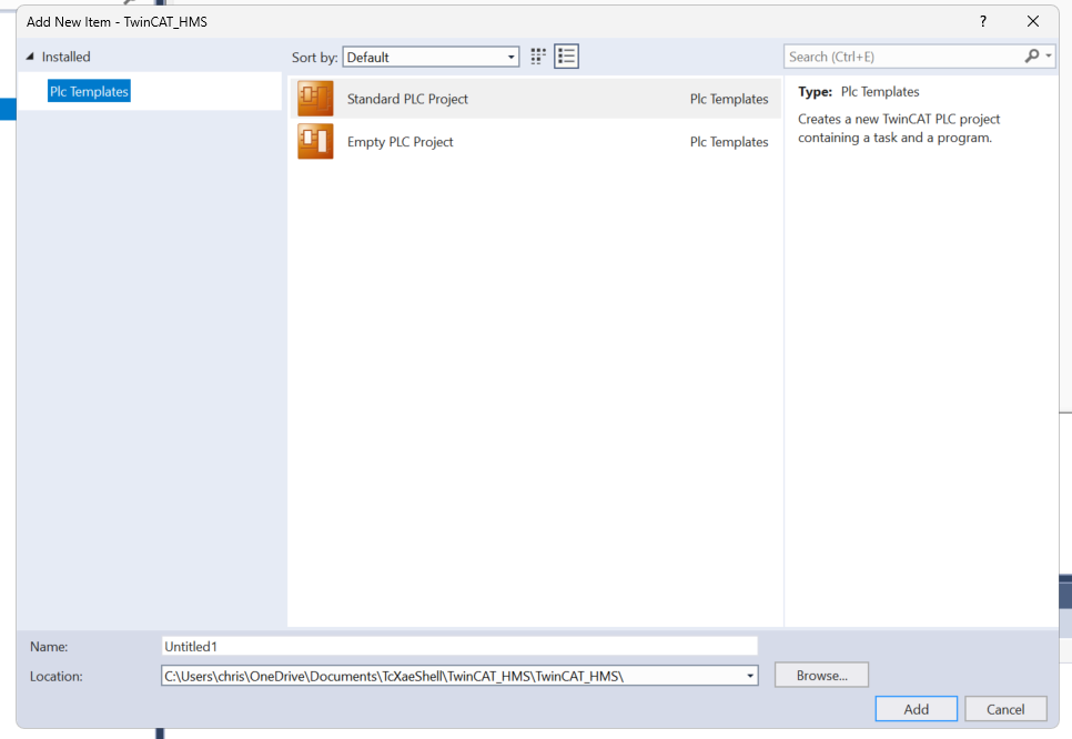
Add Standard PLC Project.
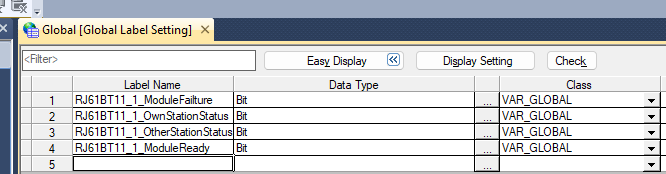
Add GVL
Add GVLs>Add>Global Variable List to define the IOs to be mapped to the Anybus Gateway.
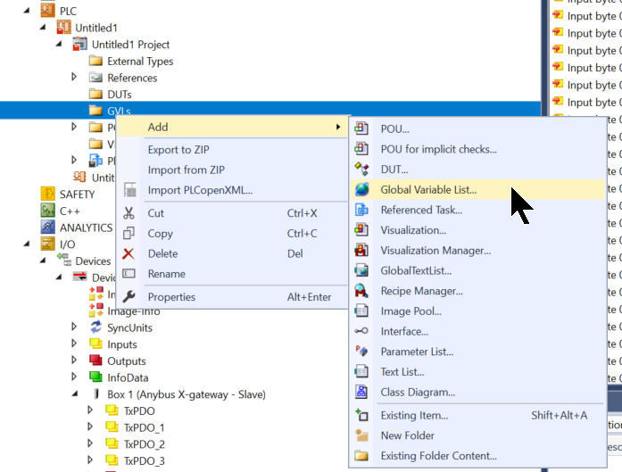
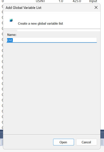
Add GVL.
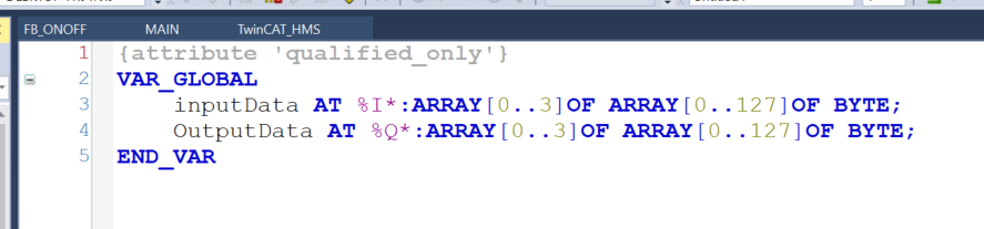
Define Process IO data as shown in the figure below.
Function Block
The next step is to create a simple FB.
FB_ONOFF
This one turns qON on and off repeatedly according to the iSetTime value.
| FUNCTION_BLOCK FB_ONOFF VAR_INPUT iTrigger:BOOL; iSetTime:REAL; END_VAR VAR_OUTPUT qON:BOOL; END_VAR VAR TON:TON; TON1:TON; _iSetTime:DINT; END_VAR TON.PT:=DINT_TO_TIME(REAL_TO_DINT(iSetTime)*1000); TON1.PT:=DINT_TO_TIME(REAL_TO_DINT(iSetTime)*1000); TON.IN:=iTrigger AND NOT TON1.Q; TON1.in:=iTrigger AND TON.Q; TON(); TON1(); qON:=TON.Q; |
MAIN
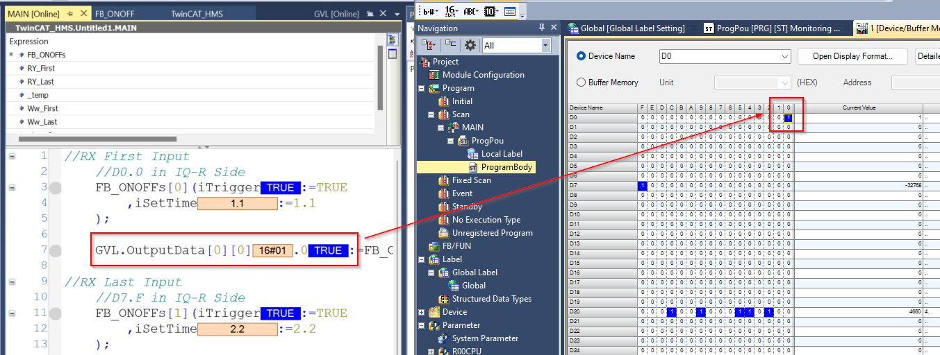
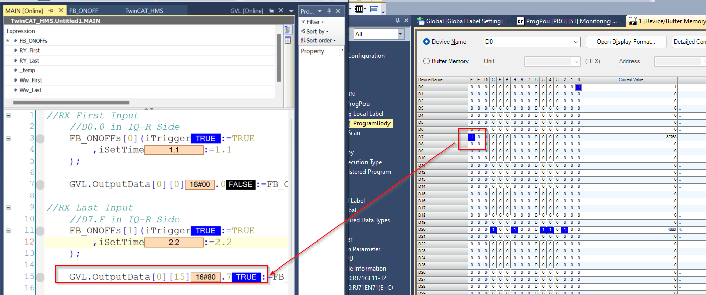
Finally, data is written to the communication area to confirm communication.
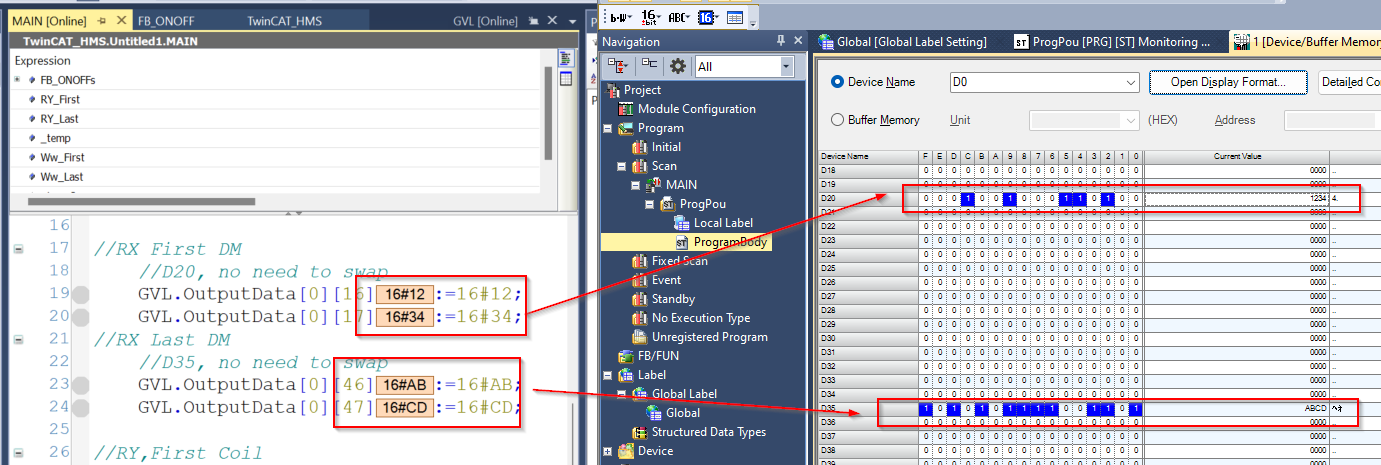
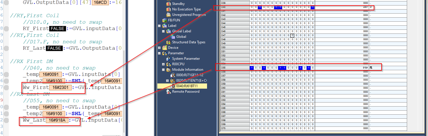
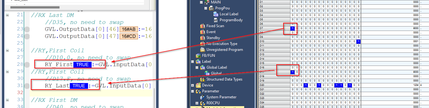
| PROGRAM MAIN VAR FB_ONOFFs:ARRAY[0..1]OF FB_ONOFF; RY_First,RY_Last:BOOL; _temp:INT; Ww_First,Ww_Last:INT; _temp2:INT; END_VAR //RX First Input //D0.0 in IQ-R Side FB_ONOFFs[0](iTrigger:=TRUE ,iSetTime:=1.1 ); GVL.OutputData[0][0].0:=FB_ONOFFs[0].qON; //RX Last Input //D7.F in IQ-R Side FB_ONOFFs[1](iTrigger:=TRUE ,iSetTime:=2.2 ); GVL.OutputData[0][15].7:=FB_ONOFFs[1].qON; //RX First DM //D20, no need to swap GVL.OutputData[0][16]:=16#12; GVL.OutputData[0][17]:=16#34; //RX Last DM //D35, no need to swap GVL.OutputData[0][46]:=16#AB; GVL.OutputData[0][47]:=16#CD; //RY,First Coil //D10.0, no need to swap RY_First:=GVL.inputData[0][0].0;//RY,First Coil //D17.F, no need to swap RY_Last:=GVL.inputData[0][15].7; //RX First DM //D40, no need to swap _temp:=GVL.inputData[0][16]; _temp2:=SHL(_temp,8); Ww_First:=GVL.inputData[0][17]+_temp2; //RX Last DM //D55, no need to swap _temp:=GVL.inputData[0][46]; _temp2:=SHL(_temp,8); Ww_Last:=GVL.inputData[0][47]+_temp2; |
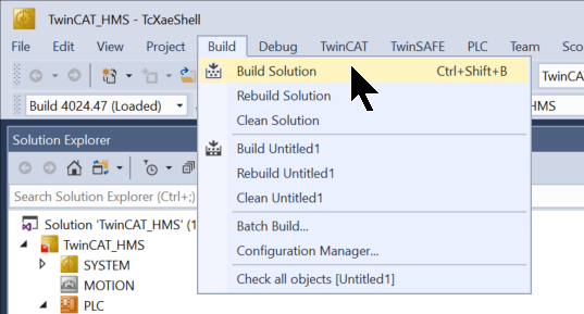
Build Solution
Compile the project under Build>Build Solution.
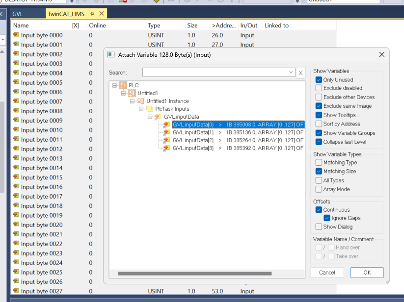
Link Input
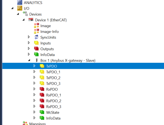
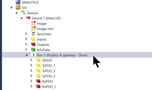
Click Box1>TxPDO for Mapping with Process Input data.
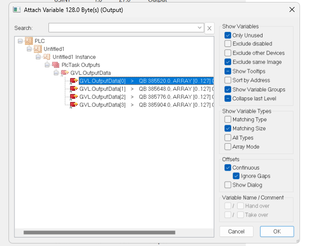
Select all > right click > Change Mulit Link.
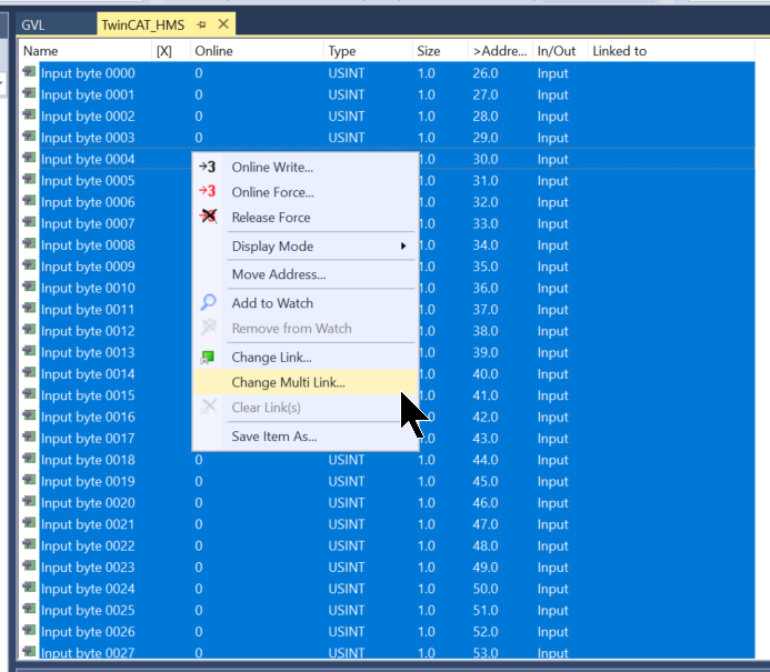
Select the Process Input you defined earlier.Mapping other Process Inputs should be done in the same manner.
Link Output
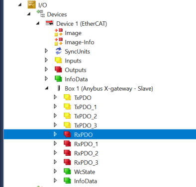
Click Box1>RxPDO for Mapping with Process Output data.
Select all > right click > Change Mulit Link.
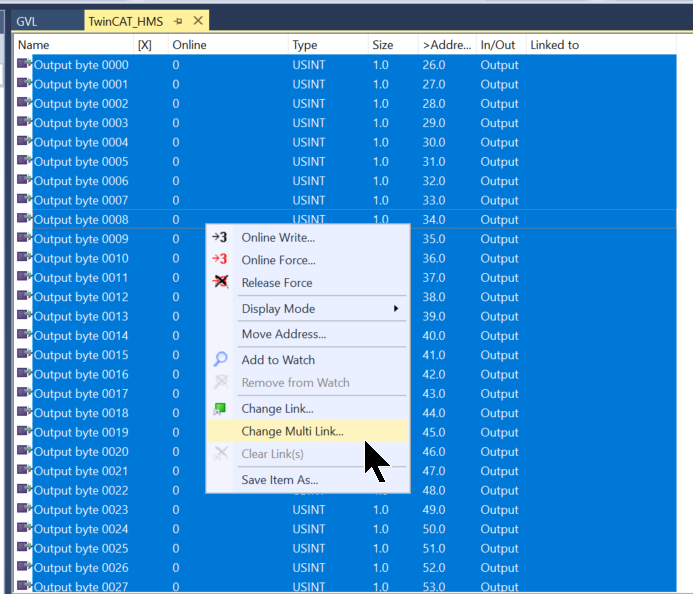
Select the Process Output you defined earlier.Mapping other Process Outputs is done in the same way.
Activate Configuration
Click Activate Configuration to download the hardware configuration to TwinCAT Runtime.
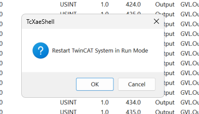
Proceed with Ok.
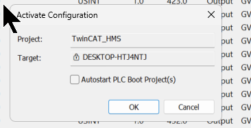
OK sets TwinCAT Runtime to Run Mode.
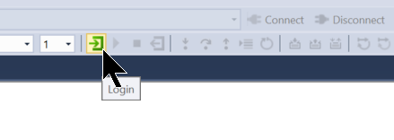
Login
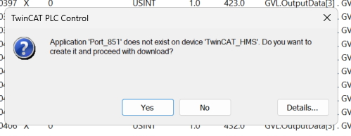
Download the program in Login.
Proceed with Yes.
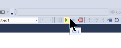
Start
Start launches Runtime.
Result
Finally, Let’s check the communication.
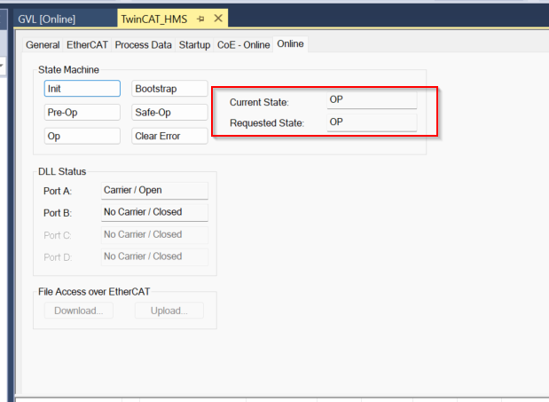
The Operation State of the Anybus Gateway is currently OP.
The next step is to check the validity of the data from the WcState variable.
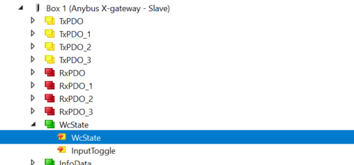
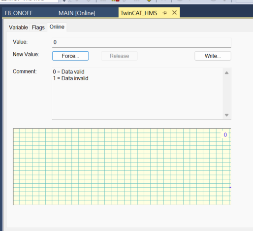
Currently 0, so the data is valid.
There are no errors on the GXWORKS3 side either.
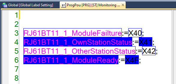
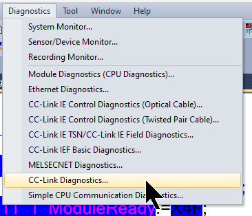
Click Diagnostics>CC-Link Diagnostics.
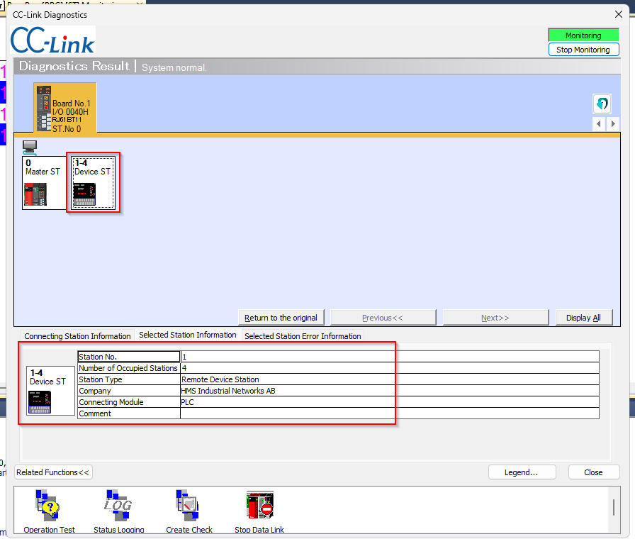
Communication is currently normal between the RJ61BT11 and the Anybus Gateway.
Output data on the TwinCAT side could also be received by RX and other devices.
Input data on the TwinCAT side could also be received by RY and others.
There are no errors in the CC-Link module and the Anybus module.