In this article, I set up a Modbus TCP/IP Server on a Pilz CPU and program a Modbus TCP Client from an Omron NX CPU to access it.
Let’s start!

Thanks!
This article was made possible thanks to Omron Corporation and Pilz Japan. for lending us their equipment. Thank you very much.
オムロン株式会社
As a leading automation company, OMRON Corporation develops a wide range of businesses, including control equipment mainly for factory automation, electronic components, social systems such as automatic ticket gates at railway stations and power conditioners for solar power generation, and healthcare, and provides products and services in some 120 countries and regions. The company provides products and services in some 120 countries and regions.

This is the website of OMRON Corporation.
PILZ
PILZ supports FA sites as a total solution supplier with solutions in safety and automation technology, guaranteeing the safety of people as well as machines and the environment, and how safely machines and equipment can be operated. PILZ has 42 subsidiaries and branches worldwide and is active in various sectors such as packaging, the automotive industry, robotic applications, as well as wind power and railway technology.

Office:
ピルツジャパン株式会社
〒222-0033
横浜市港北区新横浜3-17-5
いちご新横浜ビル 4階
HP
Pilz
IP Connections?
In the PSS4000 system, IP connections allow communication between the CPU and third-party devices via Modbus TCP/Raw TCP/Raw UDP; from the perspective of the PSS4000 system, these connections are all external communications.
Max Number of IP connections?
The maximum number of IP Connections on a PSS4000 system can be set from the tool, but cannot exceed 32. However, SafetyNet p Connections are not managed by IP Connections, so the number of Connections is not calculated.
IP Connections Name?
Always ensure that the names of the IP Connections in the project do not duplicate.
Local Port Number?
Make sure that the Local Port (CPU itself) used by IP Connections in the project is also not duplicated: on a CPU, one Port and one IP Connection is a one-to-one relationship and when using Raw TCP/UDP, the relevant Port is already occupied by another Services, so make sure that the relevant Port has already been occupied by another Services. (And the Port numbers available for Raw TCP/UDP Services range from 1024 to 5000, and for UDP from 49152 to 65535.)
Modbus TCP
Data Area(Server)
This is the Data Area of the PSS4000 System Modbus TCP Server Side. Note that the PSS4000 starts from 0, but some manufacturers start from 1.
| Data Area | Modbus Synatax | R/W | Range | Example |
| Coils(Bit) | 0x[xxxxx] | Read/Write capable | 0x00000 to 0x65535. | 0x01234 |
| Discrete Inputs(Bit) | 1x[xxxxx] | Read only | 0x00000 to 0x65535. | 1×5123 |
| Input Register(Word 16 bit) | 3x[xxxxx] | Read only | 0x00000 to 0x65535. | 3×0111 |
| Holding Register(Word 16 bit) | 4x[xxxxx] | Read/Write capable | 0x00000 to 0x65535. | 4×1234 |
Function Codes
This is the Function Code used when accessing Modbus TCP Server data on the Client side PSS4000.
| Data Area | Data Length | FC(Writing From Client) | FC (Reading From Client) |
| 0x[xxxxx] Coils | =1Bit | FC=05(Write Single Coil) | FC=01(Read Coil,Range:1-2000) |
| 0x[xxxxx] Coils | >1Bit | FC=15(Write Multiple Coils,1-1968) | FC=01(Read Coil,Range:1-2000) |
| 1x[xxxxx]Discrete Input | >=1Bit | – | FC=02(Read Discrete Input,Range:1-2000) |
| 3x[xxxxx]Read Input Register | >=1Word | – | FC=04(Read Input RegisterRange:1-125) |
| 4x[xxxxx]Read Holding Register | =1Word | FC=06(Write Single RegisterRange:1-123) | FC=03(Read Holding RegisterRange:1-125) |
| 4x[xxxxx]Read Holding Register | >1 Word | FC=16(Write Multiple RegisterRange:1-123) | FC=03(Read Holding RegisterRange:1-125) |
Reference Link
http://soup01.com/en/category/omron/
http://soup01.com/en/category/pilz_en/
Implementation
Pilz Side
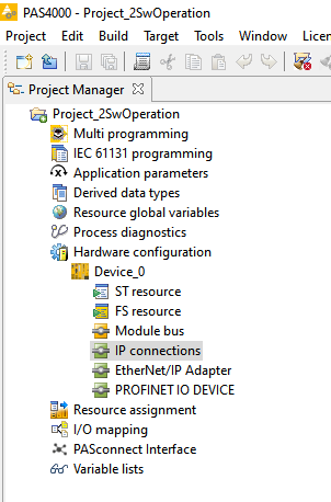
Start the PAS4000 and click on IP Connections from Hardware Configuration.
The Connections settings screen is displayed.
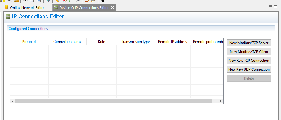
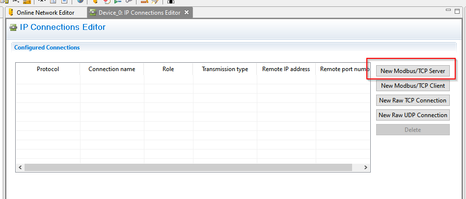
New Modbus/TCP Server
Click on “New Modbus/TCP Server” to build a new Modbus/TCP Server from the Pilz CPU.
Done!The Sever is created and the Register configuration screen is visible.

Server
Network Settings
Connection name
The name of its IP Connections.
Local Port Number
Range:1-65535, Default is 502 When building the Modbus TCP Client, match this Port number.
Remote IP address
Default is 0.0.0.0. Modbus TCP Client IPs that can be connected. 0.0.0.0 means that all IPs can also be connected.
Remote Port number
Range: 0-65535, Default is 0. The Modbus TCP Client Port numbers that can be connected to; if 0, all ports can also be connected.
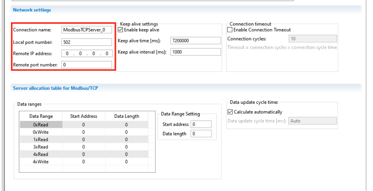
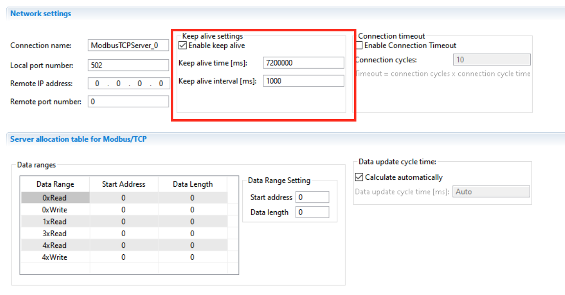
Keep alive settings
Enable keep alive
Check=Keep Alive.
Keep alive time[ms]
Maximum Keep Alive time when there is no data Traffic between Server and Client.
Keep alive interval[ms]
Maximum Keep Alive message latency between Server and Client.
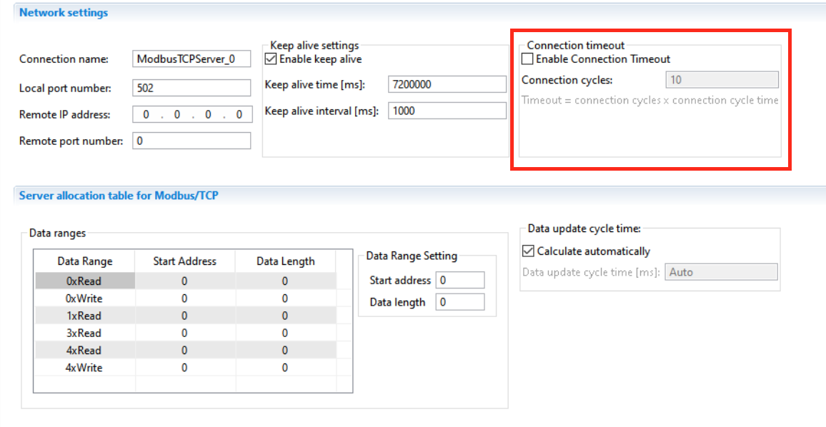
Connecton timeout
The PSS4000 system can detect a Timeout if no response is received from the Client within the Monitor time. The calculation is: Timeout=(Number of Connection cycles)*(Connection cycle time)
Enable Connection Timeout
Check to monitor Timeout.
Connection Cycle
Number of Connection cycles for Timeout detection.
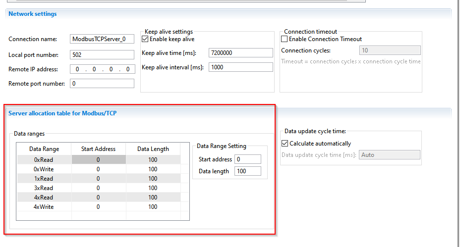
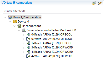
Server Allocation Table
The size and Start Address of each Allocation of the PSS4000 system can be set.
Program
| PROGRAM POU_2 VAR ModbusCoil00_Read AT %i*:ARRAY[0..99]OF BOOL; ModbusCoil00_Write AT %Q*:ARRAY[0..99]OF BOOL; ModbusCoil01_Write AT %Q*:ARRAY[0..99]OF BOOL; ModbusRegister03_Write AT %Q*:ARRAY[0..99]OF WORD; ModbusRegister04_Write AT %Q*:ARRAY[0..99]OF WORD; ModbusRegister04_Read AT %I*:ARRAY[0..99]OF WORD; b1,b2:BOOL; w1,w2:WORD; END_VAR //Read Coils Function Code01 ModbusCoil00_Write[0]:=TRUE; ModbusCoil00_Write[99]:=TRUE; //Read Discrete Inputs Code02 ModbusCoil01_Write[1]:=TRUE; ModbusCoil01_Write[98]:=TRUE; //Write Multiple Coils Code15 b1:=ModbusCoil00_Read[0]; b2:=ModbusCoil00_Read[99]; // w1:=ModbusRegister04_Read[0]; w2:=ModbusRegister04_Read[99]; //Read Input Register Code04 ModbusRegister03_Write[0]:=WORD#99; ModbusRegister03_Write[99]:=WORD#123; //Read Holding Register Code 03 ModbusRegister04_Write[0]:=WORD#56; ModbusRegister04_Write[99]:=WORD#912; END_PROGRAM |
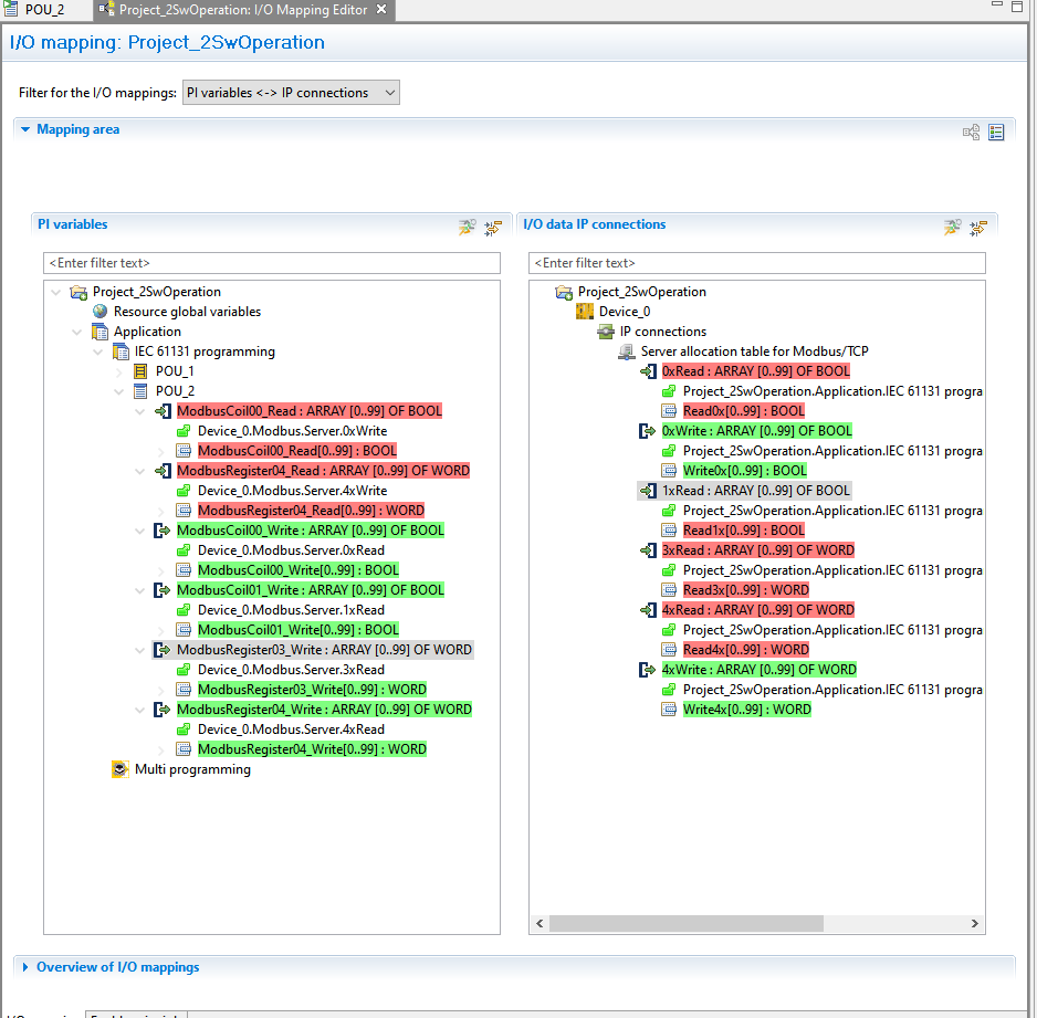
Mapping
After programme preparation, the next step is I/O Mapping.
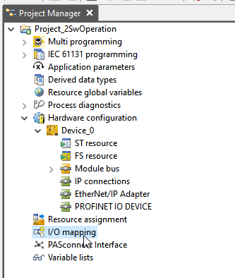
You should see the respective Register of Modbus TCP Server in IP Connections.
Make sure that you do not make a mistake Mapping.
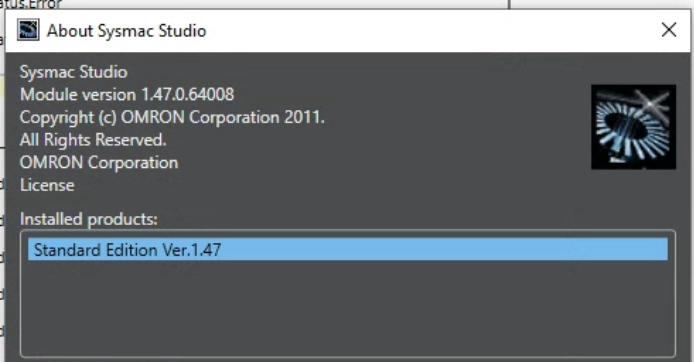
Omron Side
This is the Sysmac Studio Version that I use.
VAR
The following section introduces the variables required when using Ethernet communication with the Omron NX CPU.
_EIP_EthXXOnlineSta
| Variable Name | Type | Description |
| _EIP_EthOnlineSta | BOOL | True=NX The Ethernet/IP Port with built-in CPU becomes available. |
| _EIP1_EthOnlineSta | BOOL | True=NX CPU built-in Ethernet/IP Port1 available. |
| _EIP2_EthOnlineSta | BOOL | True=NX CPU built-in Ethernet/IP Port2 available. |
| _EIPIn1_EthOnlineSta | BOOL | True=NY CPU built-in Ethernet/IP Port1 available. |
Socket
| Variable Name | Type | Description |
| Handle | UDINT | 0=Close the TCP connection |
| SrcAdr | _sSOCKET_ADDRESS | Local IP and Port number of the NX CPU |
| DstAdr | _sSOCKET_ADDRESS | Remote Server IP and Port number |
_sSOCKET_ADDRESS
| Variable Name | Type | Description |
| PortNo | UINT | Port number |
| IpAdr | String | IP address |
_eMDB_FUN
| Enum Name | Range | Data Type |
| _MDB_READ_COILS | Read Outputs(Bit,1-2000) | Bool/Bool Array |
| _MDB_READ_DISCRETE_INPUTS | Read Inputs(Bit,1-2000) | Bool/Bool Array |
| _MDB_READ_HOLDING_REGISTERS | Read Holding Register(Word,1-125) | Word/Word Array |
| _MDB__READ_INPUT_REGISTERS | Read Input Register(Word,1-125) | Word/Word Array |
| _MDB_WRITE_SINGLE_COIL | Write Single Coils(Bit,1) | Bool/Bool Array |
| _MDB_WRITE_SINGLE_REGISTER | Write Holding Register(Word,1) | Word/Word Array |
| _MDB_WRITE_MULTIPLE_COILS | Write multiple outputs (Bit,1968) | Bool/Bool Array |
| _MDB_WRITE_MULTIPLE_REGISTERS | Write multiple holding registers (Word,123) | Word/Word Array |
Function Block
SktTCPConnect
This Function Block can be used to send a connection request from the Omron CPU to the Remote Server. If the connection is successful, Done=True.
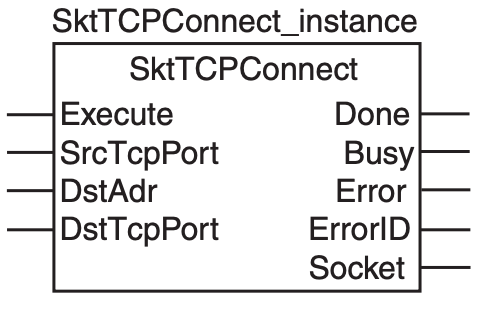
VAR_INPUT
| Variable Name | Type | Description |
| SrcTcpPort | Bool | Specifies the Port of the Local (Omron CPU).0=Automatically uses any available Port above 1024.Default=0.0=Automatically uses any available Port above 1024.0=Automatically uses any available Port above 1024. |
| DstAdr | String | You can specify the Remote Server’s IP address in a string of up to 200 Bytes. |
| DstTcpPort | UINT | Remote Server connection Port number (from 1-65535) |
VAR_OUTPUT
| Variable Name | Type | Description |
| Done | Bool | Successful FB execution |
| Busy | Bool | FB running |
| Error | Bool | FB has errors. |
| ErrorID | WORD | FB error information. |
| Socket | _sSOCKET | Socket Variables |
SktClose
You can use this Function Block to disconnect the Socket connection between the NX CPU and Remote Server. If the execution is successful, Done=True.
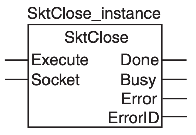
VAR_INPUT
| Variable Name | Type | Description |
| Execute | Bool | Execute with Edge UP Signal |
| Socket | Socket | Socket variables retrieved from SktTCPConnect. |
VAR_OUTPUT
| Variable Name | Type | Description |
| Done | Bool | Successful FB execution |
| Busy | Bool | FB running |
| Error | Bool | FB has errors. |
| ErrorID | WORD | FB error information. |
SktSetOption
The Function Block here can be used to set Socket communication Options.
Done=FB execution succeeded, Error=FB execution with errors.
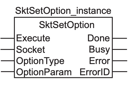
VAR_INPUT
| Variable Name | Type | Description |
| Execute | Bool | Execute with Edge UP Signal |
| Socket | Socket | Socket variables retrieved from SktTCPConnect. |
| OptionType | _sSKT_OPTION_TYPE | SocketのOption Type |
| OptionParam | BOOL | True=NO Delay is enabled.(Disable Nagle algorithm) |
VAR_OUTPUT
| Variable Name | Type | Description |
| Done | Bool | Successful FB execution |
| Busy | Bool | FB running |
| Error | Bool | FB has errors. |
| ErrorID | WORD | FB error information. |
ModbusTCPRead
This Function Block can be used to send “Read” commands from an established Connection to the Remote Modbus TCP Server.The data size read is stored in the “ReadSize” parameter and the data read is stored in the parameter assigned to ReadDat. (If an error occurs, ReadDat and ReadSize will remain unknown, so it is advisable to reset these parameters before executing the corresponding FB).
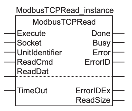
VAR_INPUT
| Variable Name | Type | Description |
| Execute | Bool | Execute with Edge UP Signal |
| Socket | Socket | Socket variables retrieved from SktTCPConnect. |
| UnitIdentifier | USINT | Unit ID Default=255 |
| ReadCmd | _sMODBUS_READ | Modbus Function Code, Size, Start Address |
| TimeOut | Time | Set Timeout time (in increments of 0.1 s), Default=2s (20). |
VAR_OUTPUT
| Variable Name | Type | Description |
| Done | Bool | Successful FB execution |
| Busy | Bool | FB running |
| Error | Bool | FB has errors. |
| ErrorID | WORD | FB error information. |
| ErrorIDEx | DWORD | FB error information 2. |
| ReadSize | UINT | Total size read.For Bit, 1-2000 (calculated in Bit units)For Word, 1-125 (calculated in Word units). |
VAR_IN_OUT
| Variable Name | Type | Description |
| ReadDat | ANY | Data read Register from Modbus TCP Server. |
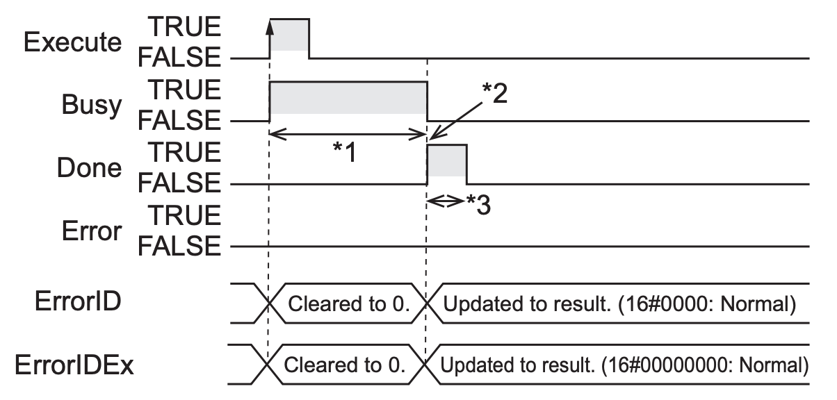
TimeChart-Normal
TimeChart-Error
ModbusTCPWrite
こちらのFunction Blockを使用すると確立されたConnectionから”Write”コマンドをRemote Modbus TCP Serverに送信することができます。書き込むデータサイズは”WriteDat”パラメータに格納され、書き込むデータはWriteDatに割り付けられた変数から転送されます。
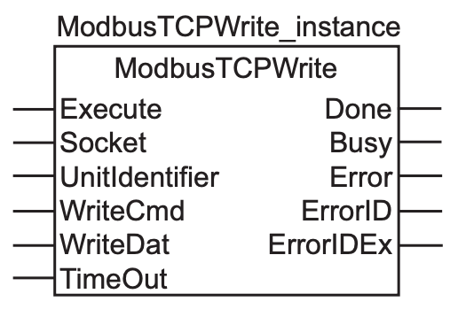
VAR_INPUT
| Variable Name | Type | Description |
| Execute | Bool | Execute with Edge UP Signal |
| Socket | Socket | Socket variables retrieved from SktTCPConnect. |
| UnitIdentifier | USINT | Unit ID Default=255 |
| WriteCmd | _sMODBUS_WRITE | Modbus Function Code, Size, Start Address |
| TimeOut | Time | Set Timeout time (in increments of 0.1 s), Default=2s (20). |
VAR_OUTPUT
| Variable Name | Type | Description |
| Done | Bool | Successful FB execution |
| Busy | Bool | FB running |
| Error | Bool | FB has errors. |
| ErrorID | WORD | FB error information. |
| ErrorIDEx | DWORD | FB error information 2. |
VAR_IN_OUT
| Variable Name | Type | Description |
| WriteDat | ANY | Data to write Register to Modbus TCP Server. |
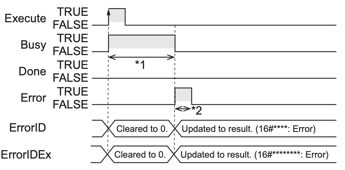
TimeChart-Normal
TimeChart-Error
Function
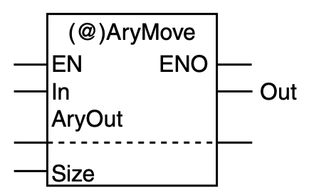
AryMove
This function can be used to transfer data between array variables. The Data Type of the source and destination can be mismatched.
VAR_INPUT
| Variable Name | Type | Description |
| In | Bool | Data From |
VAR_OUTPUT
| Variable Name | Type | Description |
| Out | Bool | Always ON |
VAR_IN_OUT
| Variable Name | Type | Description |
| AryOut | ANY | Data To |
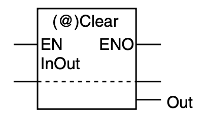
Clear
This function is used to initialize InOut variables. If the relevant variable has been set to an initial value, it will be returned to the initial value, otherwise it will be set to the Default initial value.
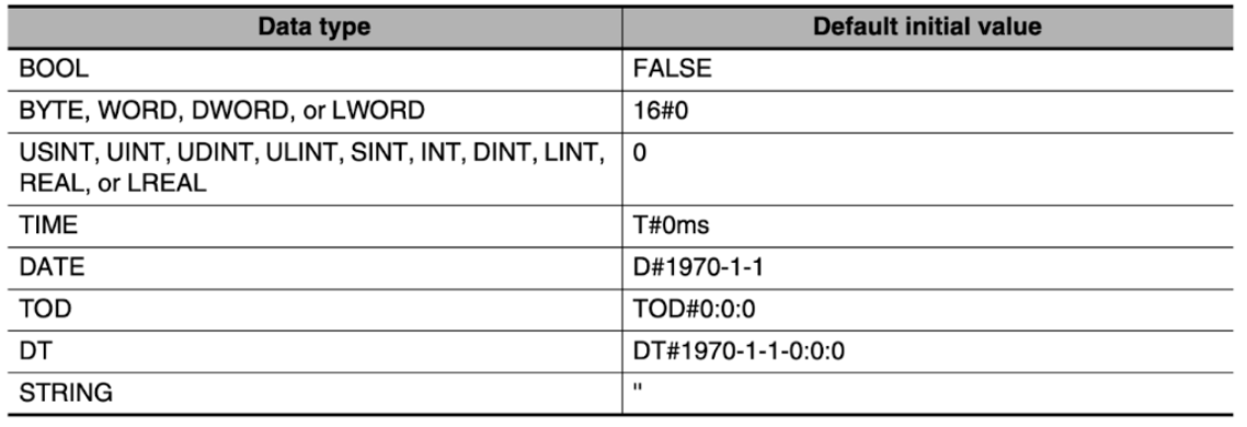
Default Initial Value
The following are the Default initial values for each data type.
VAR_INOUT
| Variable Name | Type | Description |
| InOut | ANY | Variables to be initialized |
VAR_OUT
| Variable Name | Type | Description |
| Out | Bool | AlwaysON Output |
NumToEnum
Function to convert DINT variables to Enum variables.
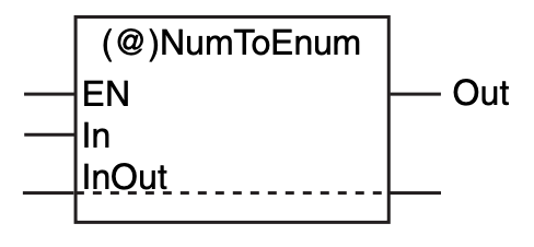
VAR_IN
| Variable Name | Type | Description |
| In | DINT |
VAR_OUT
| Variable Name | Type | Description |
| InOut | Enum | Enum variable |
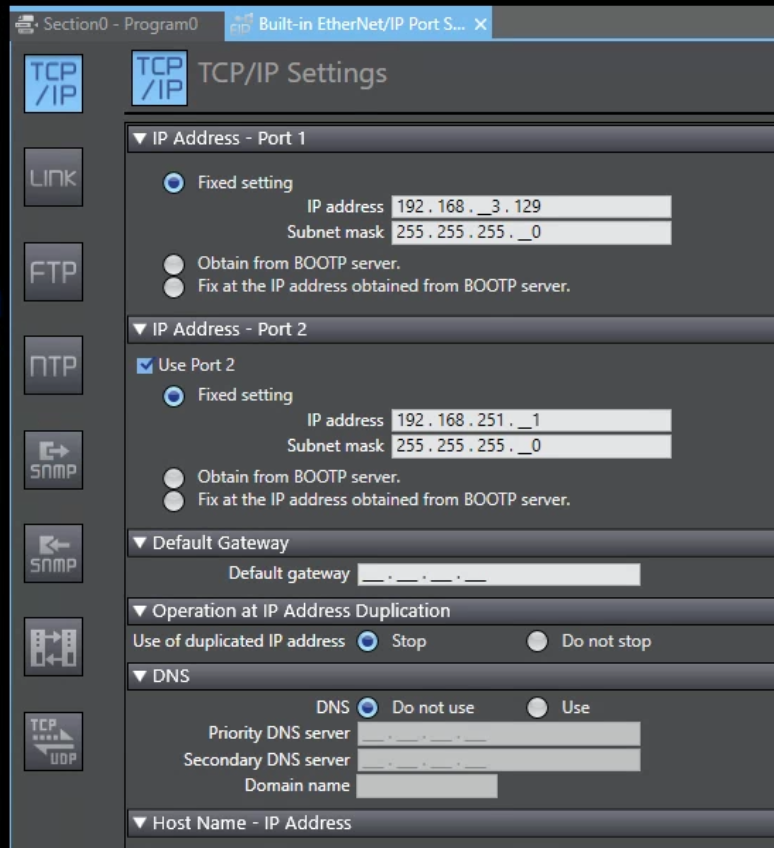
Configuration
Configure the built-in Ethernet/IP Port settings of the NX CPU.
Go to Configuration and Setup>Controller Setup>Build-in Ethernet/IP Port Settings.
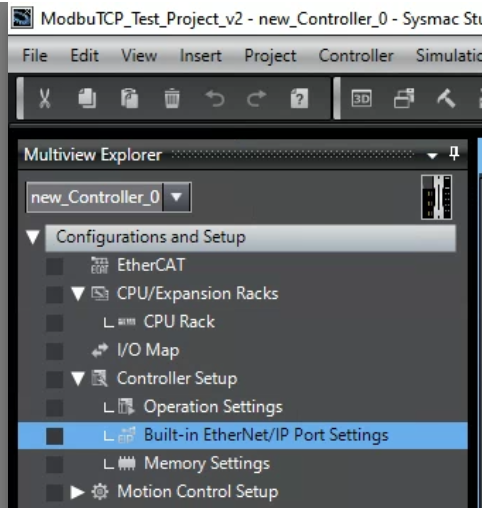
Set the IP address of the Port to be used.
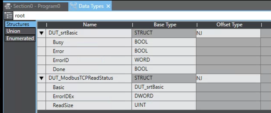
DUT
This structure is defined collectively with the Flag of Socket FB and Modbus TCP FB.
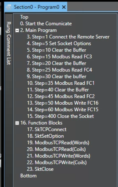
Program
Here is the Programme flow.
VAR
| Variable | Type | Description |
| _SktTCPConnect | SktTCPConnect | Instances of SktTCPConnect |
| _SktTCPClose | SktClose | Instances of SktClose |
| bExecute | BOOL | Execute SktTCPConnect FB |
| bClose | BOOL | Execute SktClose FB |
| Socket | _sSOCKET | Socket Variable |
| _ModbusTCPRead | ModbusTCPRead | Instance of ModbusTCPRead |
| bError | BOOL | |
| ModbusReadDat | ARRAY[0..99] OF word | Read Buffer (Word) used in ModbusTCPRead FB |
| ModbusWriteDat | ARRAY[0..99] OF word | Write Buffer used in ModbusTCPWrite FB |
| ModbusReadDataCoil | ARRAY[0..99] OF bool | Read Buffer (Coil) used in ModbusTCPRead FB |
| ModbusWrite_16 | ARRAY[0..99] OF word | Word array used in FC16 |
| ModbusRead_03 | ARRAY[0..99] OF word | Word sequences used in FC3 |
| ModbusRead_04 | ARRAY[0..99] OF word | Word sequences used in FC4 |
| ModbusRead_01 | ARRAY[0..99] OF bool | Bool array used in FC1 |
| ModbusRead_02 | ARRAY[0..99] OF bool | Bool array used in FC2 |
| ModbusWrite_15 | ARRAY[0..99] OF bool | Bool array used in FC15 |
| ReadCmd | _sMODBUS_READ | ModbusTCPRead commands (size, FC, etc.) |
| bReads | ARRAY[0..15] OF bool | Perform ModbusTCPRead. |
| iStep | INT | |
| bWrites | ARRAY[0..15] OF bool | Execute ModbusTCPWrite |
| bStart | BOOL | プログラムスタートする |
| R_TRIG1 | R_TRIG | Instance of startup detection |
| ModbusTCPReadStatus | DUT_ModbusTCPReadStatus | Status of ModbusTCPRead(Word)FB |
| ModbusTCPReadCoilStatus | DUT_ModbusTCPReadStatus | Status of ModbusTCPRead(Coil)FB |
| SktBasicStatus | DUT_srtBasic | Status of SktTCPConnect FB |
| SktCloseStatus | DUT_srtBasic | Status of SktClose FB |
| _SktSetOption | SktSetOption | Instance of SktSetOption FB |
| SktSetOptionStatus | DUT_srtBasic | Setting Options of SktSetOption |
| bSetOptions | BOOL | Execute SktSetOption FB |
| bOptionNoDelay | BOOL | |
| TONs | ARRAY[0..15] OF ton | |
| Dummy | BOOL | |
| _ModbusTCPWriteRegister | ModbusTCPWrite | Instance of ModbusTCPWrite FB |
| WriteCmd | _sMODBUS_WRITE | ModbusTCPWrite commands (size, FC, etc.) |
| ModbusTCPWriteRegisterStatus | DUT_ModbusTCPReadStatus | Status of ModbusTCPWrite(Word) |
| ModbusWriteDatCoils | ARRAY[0..99] OF bool | Bool array used in ModbusTCPWrite |
| _ModbusTCPWriteCoils | ModbusTCPWrite | Instance (Coils)of ModbusTCPWrite FB) |
| ModbusTCPWriteCoilsStatus | DUT_ModbusTCPReadStatus | Status of ModbusTCPWrite(Coil)FB |
Code
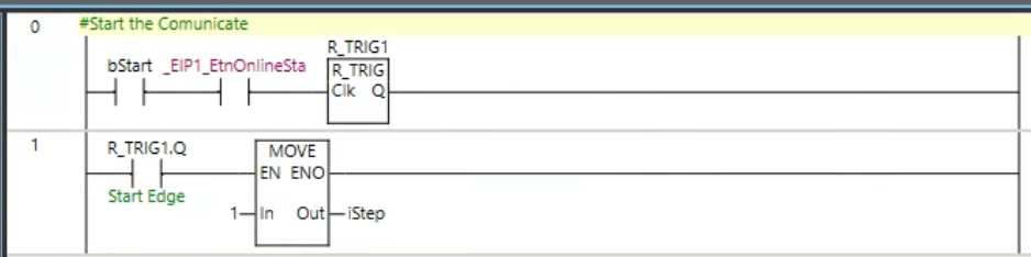
Rung0-1
- Rung0 waits for bStart to start up, and if bStart and the EIP Port are currently available, the Clk of R_TRIG1 is triggered.
- Rung1 will be iStep=1 when Start is triggered.
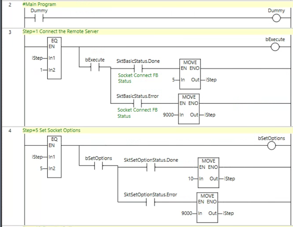
Rung2-4
- Rung2 is a Dummy circuit made to easily display Comment List.
- Rung3 executes SktTCPConnect Function Block with bExecute set to True if iStep=1, iStep=5 for successful execution if Done is True, and iStep=9000 for execution failure if Error is True.
- For Rung4, if iStep=5, bSetOptions will be True, SktSetOptions Function Block will be executed, if Done is True, iStep=10 for successful execution, and if Error is True, iStep=9000 for failed execution.
Rung5-7
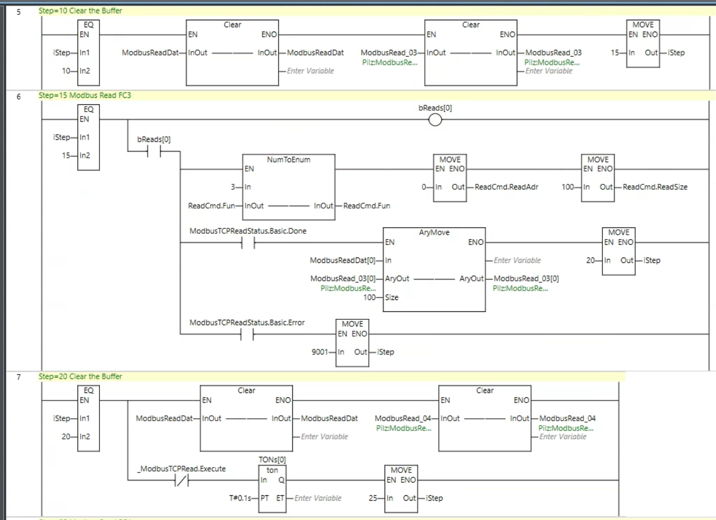
- Rung5 has iStep=10, it means that the NX CPU and Remote Server are successfully connected.Clear Buffer and set iStep to 15 before sending to ModbusTCP Server.
- Rung6 transfers the settings to ReadCmd to get Modbus Function Code3, Register 0 to 100, at the same time we will set True to bRead[0] which triggers the Function Block of ModbusTCPRead. If Done=True, it means that FB execution was successful, iStep=20 is reached. If Error=True, i.e., there was an error in FB execution, iStep=9001 is reached.
- Rung7 clears Buffer in preparation for the next ModbusRead and sets iStep to 25 after a 0.1s Delay.
Rung8-9
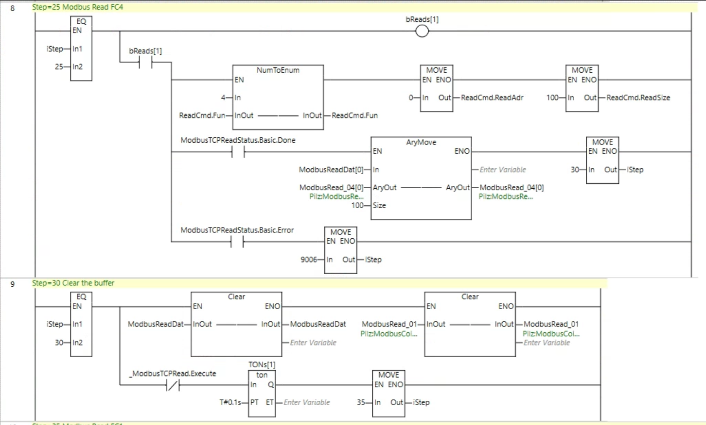
- Rung8 transfers the settings to ReadCmd to get Modbus Function Code4, Register 0 to 100.at the same time bRead[1] which triggers the Function Block of ModbusTCPRead to True. If Done=True, i.e. FB execution was successful, iStep=30 will be set. If Error=True, i.e. there was an error in FB execution, iStep=9006 will be set.
- Rung9 clears Buffer in preparation for the next ModbusRead and sets iStep to 35 after a 0.1s Delay.
Rung10-11
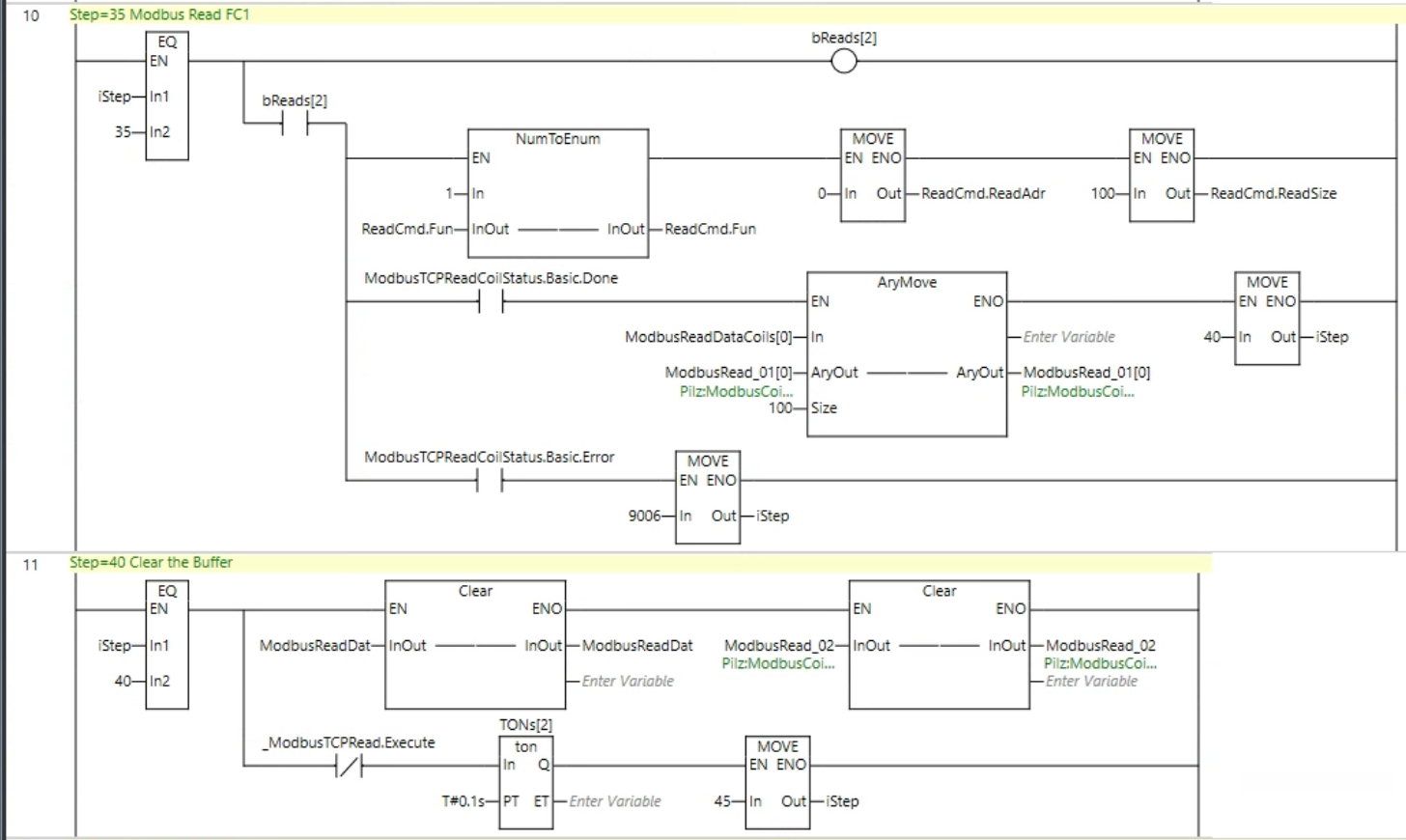
- Rung10 transfers the settings to ReadCmd to get Modbus Function Code1, Coil 0 to 100.At the same time bRead[2] is True, which triggers the Function Block of ModbusTCPRead. If Done=True, i.e. FB execution was successful, iStep=40 will be set. If Error=True, i.e. there was an error in FB execution, iStep=9006 will be set.
- Rung11 clears Buffer in preparation for the next ModbusRead and sets iStep to 45 after a 0.1s Delay.
Rung12
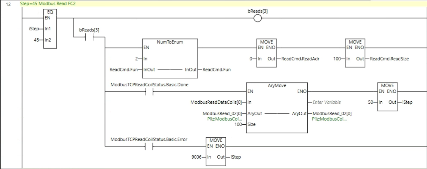
- Rung12 transfers the settings to ReadCmd to get Modbus Function Code2, Coil 0 to 100, at the same time bRead[3], which triggers the Function Block of ModbusTCPRead, is True. If Done=True, i.e. FB execution was successful, iStep=50 will be set. If Error=True, i.e. there was an error in FB execution, iStep=9006 will be set.
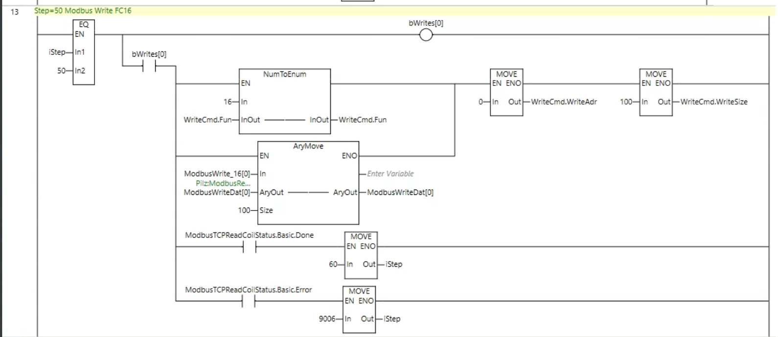
Rung13
- Rung13 transfers the settings to WriteCmd to write Modbus Function Code 16, Register 0 to 100, at the same time bWrite[0], which triggers the Function Block of ModbusTCPWrite, is True. If Done=True, i.e., FB execution was successful, then iStep=60; if Error=True, i.e., there was an error in FB execution, then iStep=9006.
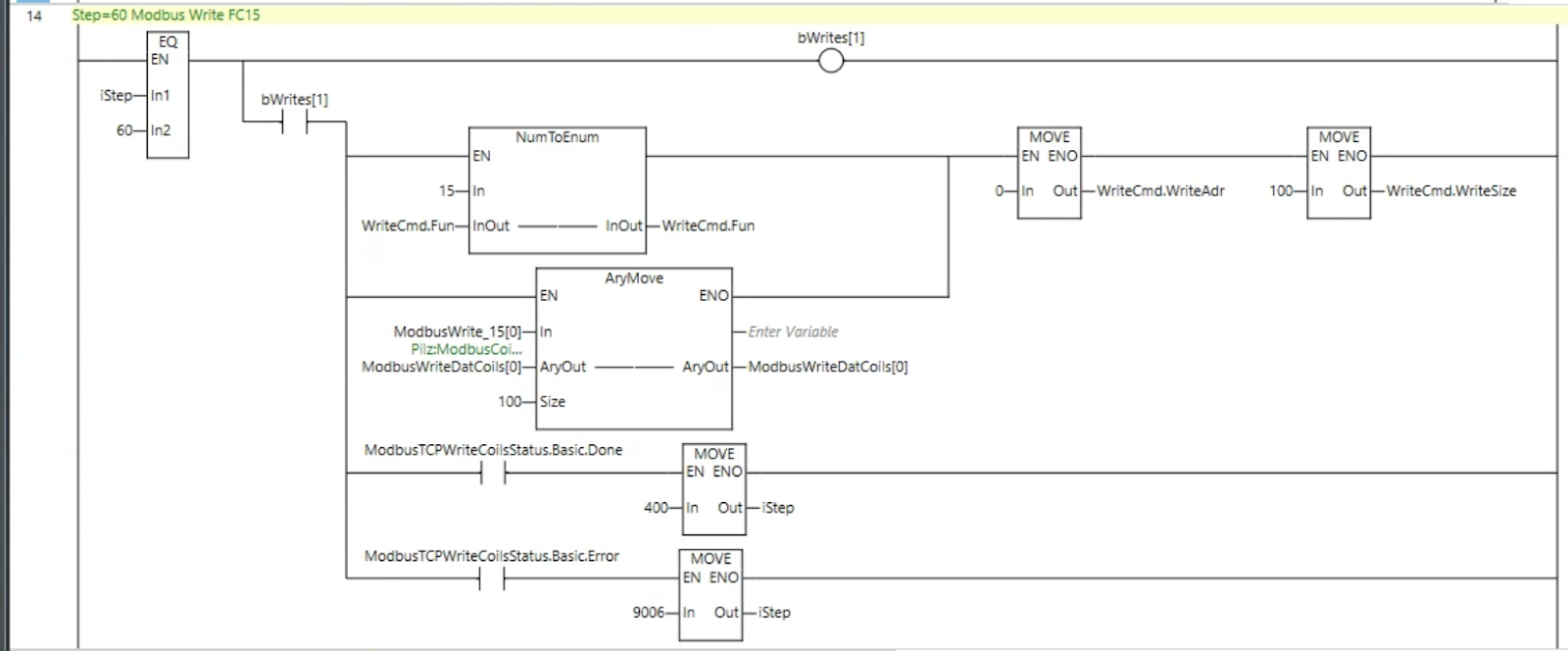
Rung14
- Rung14 transfers the settings to WriteCmd to write Modbus Function Code15, Coil 0 to 100, at the same time as bWrite[0], which triggers the Function Block of ModbusTCPWrite, is True. If Done=True, i.e. FB execution was successful, then iStep=400, if Error=True, i.e. there was an error in FB execution, then iStep=9006.
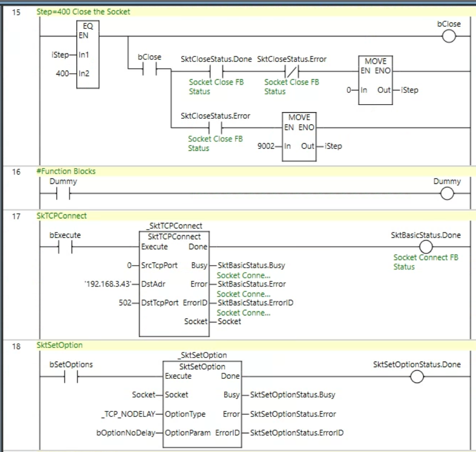
Rung15-18
- Run15 sets iStep=400 and disconnects the Remote Server; if Done=True, the execution succeeds and iStep=0; if Error, the execution fails and iStep=9002.
- Rung16 is a Dummy circuit made to easily display the Comment List.
- Rung17 calls the Function Block of SktTCPConnect.
- Rung18 calls the Function Block of SktSetOptions.
Rung 19-20
- Rung19 calls the Function Block of ModbusTCPRead (for Register).
- Rung20 calls the Function Block for ModbusTCPRead (for Coils).

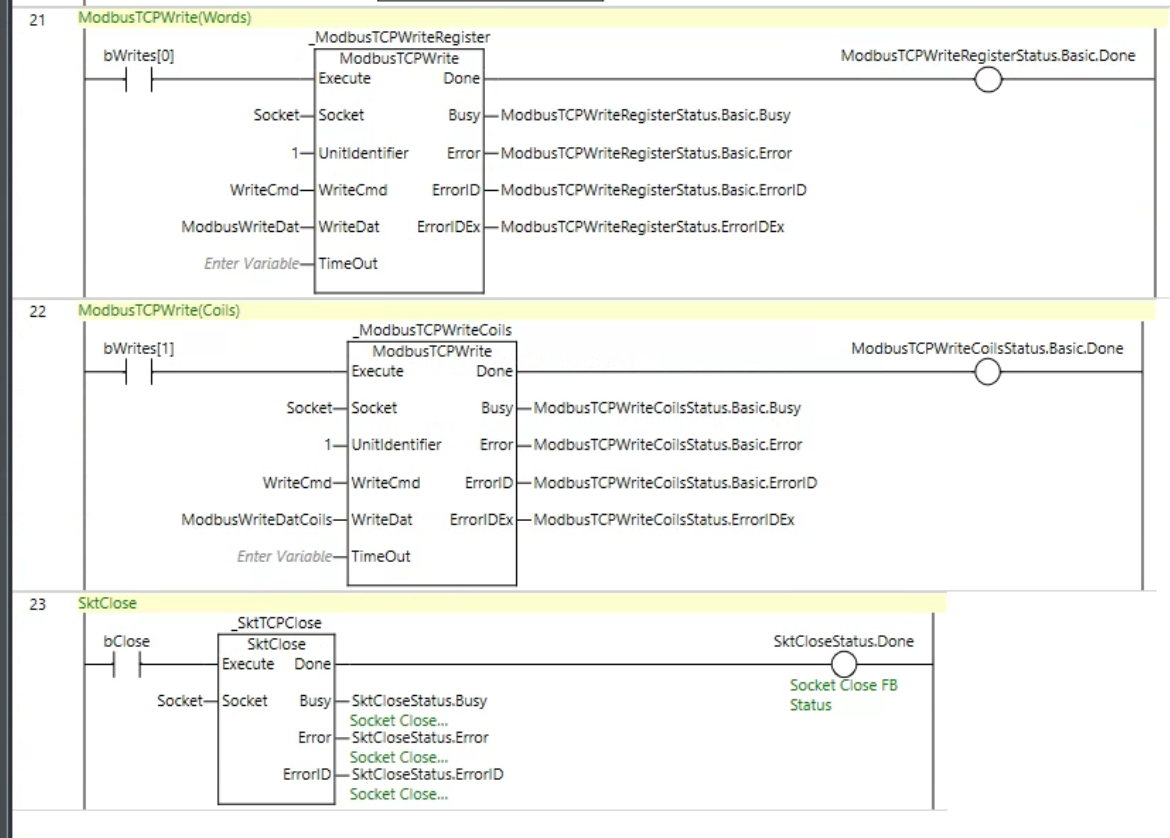
Rung21-23
- Rung21 calls the Function Block of ModbusTCPWrite (for Register).
- Rung22 calls the Function Block for ModbusTCPWrite (for Coils).
- Rung23 calls Function Block for SktClose.
Download
Download the Sample Project from this link.
https://github.com/soup01Threes/OMRON/blob/main/ModbuTCP_Test_with_pilz.smc2