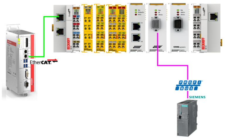
In this article, we will use Beckhoff’s EL6731 to set up Profibus Master and communicate with Siemens’ S7-315 via Profibus. Let’s get started!
Reference Link
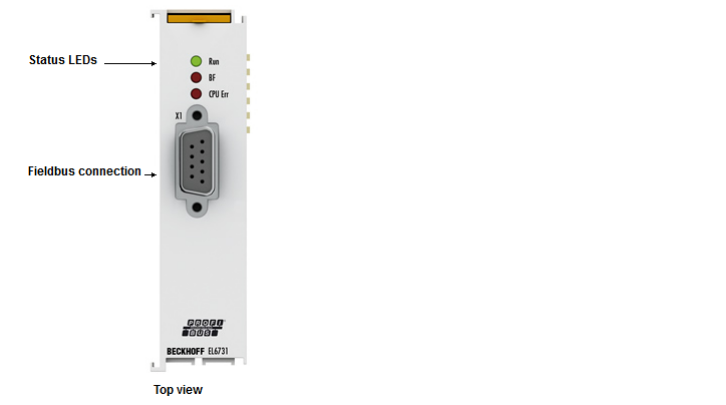
EL6731?
The PROFIBUS Master Terminal EL6731 supports the PROFIBUS protocol and allows integration of any PROFIBUS device in an EtherCAT terminal network, including high-precision isochronous mode for axis control and extended diagnostic options. It is equipped with the latest version of PROFIBUS technology, including high-precision isochronous mode for axis control and extended diagnostic options.
The EL6731 also supports different polling rates for PROFIBUS slaves.
- Cycle times from 200 µs possible
- PROFIBUS DP, PROFIBUS DP-V1, PROFIBUS DP-V2
- Master or slave up to 12 Mbit/s
- Powerful parameter and diagnostic interface
- Free error management for each bus user.
- Bus configurations can be read and “GSD” files assigned automatically
Like the FC3101 PROFIBUS PCI card, the EL6731 can be connected to a PROFIBUS network. However, this terminal does not require a PCI slot in the industrial PC, allowing for a more space-saving implementation.
PROFIBUS cabling
The physical aspects of data transmission are defined in the PROFIBUS standard (see PROFIBUS layer 1: Physical Layer). The type of area in which a fieldbus system can be used is largely determined by the choice of transmission medium and physical bus interface. In addition to the safety of the transmission, the cost and work involved in obtaining and installing the bus cables are also of great importance.
*** Translated with www.DeepL.com/Translator (free version) ***
Termination resistors
In systems with more than one station, all devices are wired in parallel, and both ends of the PROFIBUS cable must be terminated with resistors.
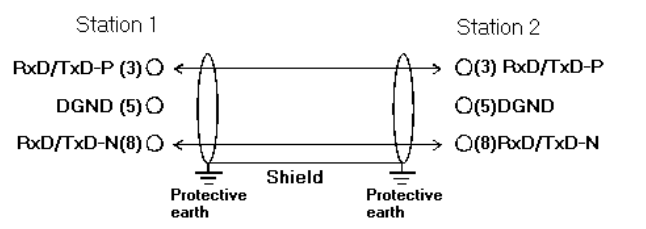
9-pin D-Sub
Pin 6 transfers 5VDC and pin 5 transfers GND for active termination resistors. These should never be used for any other function. Pin 3 and pin 8 also transfer the PROFIBUS signal. They should never be interchanged.

Synchronization
In TwinCAT Run Mode, the EL6731 always synchronizes with the highest priority task to which the variable is linked.
A separate EtherCAT telegram is defined for each EL6731. The cycle time of the corresponding task is displayed in the cycle time of the “EL6731” tab of the master as soon as the mapping is created. It is possible to configure for a task whether the I/O at the start of the task is updated or not.
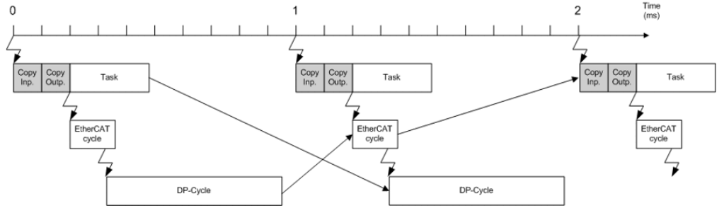
I/O at Task Start
If the setting “I/O at Task Start” Checkbox is selected (default setting for NC tasks), EtherCAT telegrams are transferred before the task starts.
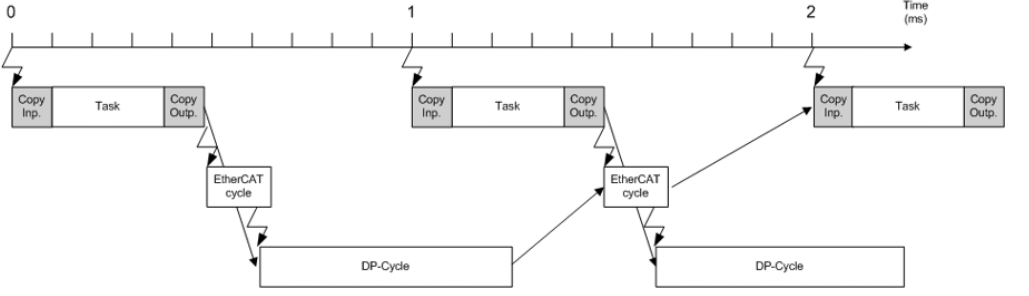
I/O not at Task Start
If the setting “I/O at Task Start” Checkbox is not selected (default setting for PLC tasks), the EtherCAT telegrams are transferred after task completion. Compared to “I/O at Task Start”, the EtherCAT telegrams will swing according to the execution time of the task, but the outputs will be updated for one cycle.
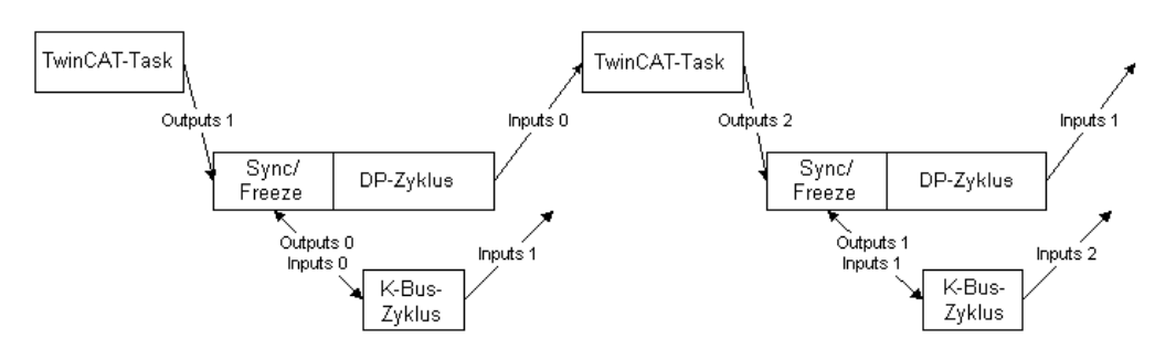
Sync/Freeze functionality
Sync is used to output the outputs of multiple slaves simultaneously, while Freeze is used to read the inputs of multiple slaves simultaneously.
- Outputs are written at the beginning (I/O at task start) or at the end (I/O other than at task start) of the task cycle.
- A PROFIBUS cycle has started.
- The Sync/Freeze Telegram is sent at the beginning of the PROFIBUS cycle.
- This causes the bus coupler to start a K-bus cycle with the output from the last task cycle and transfers the input from the last K-bus cycle.
- The master sends the current output to each slave and picks up the transferred input.
- The inputs are read at the start of the next task cycle.
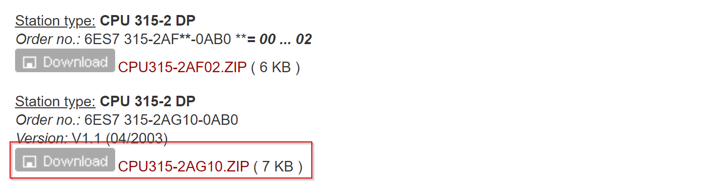
Download GSD File
The Profibus Slave used in this article is Siemens’ CPU 315-2 DP, so please download the CPU 315-2 DP GSD File from the link below.
https://support.industry.siemens.com/cs/document/113652/profibus-gsd-files-simatic?dti=0&lc=en-JP
Implementation
Siemens Side
Start building from the Siemens CPU 315-2 DP side.
Hardware Configuration
Double-click S7300 Station.
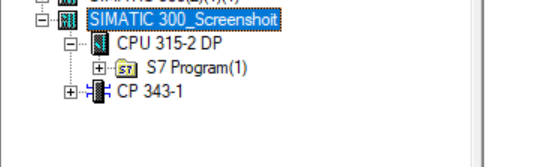
Open the Hardware item inside.
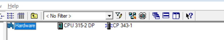
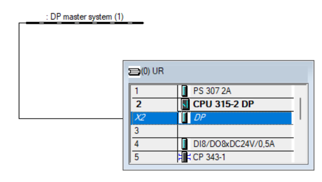
This is the screen for building Hardware Configuration for CPUs such as the S7-300.
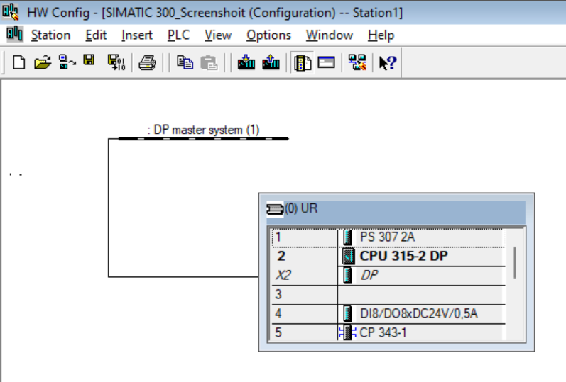
Configure DP
The current DP Port of the CPU 315-2 DP is set as Profibus Master. The Mitsubishi IQ-R RJ71PB91V used in this article can only support Profibus Master, so the CPU 315-2 DP must be set as Slave.
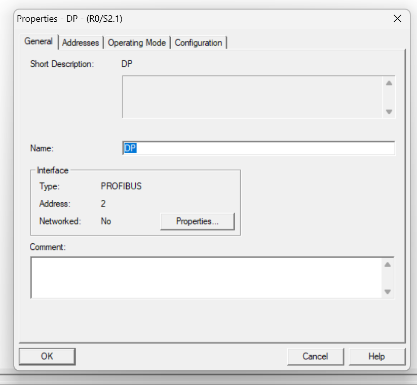
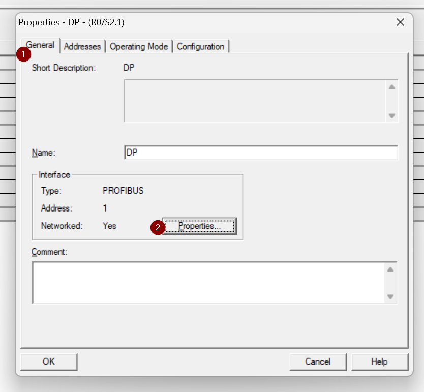
This is the DP Port setting screen.
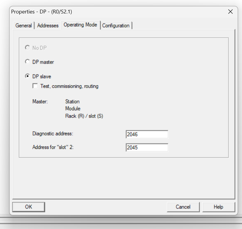
Operating Mode
Open the Operation Mode tab and set DP slave.
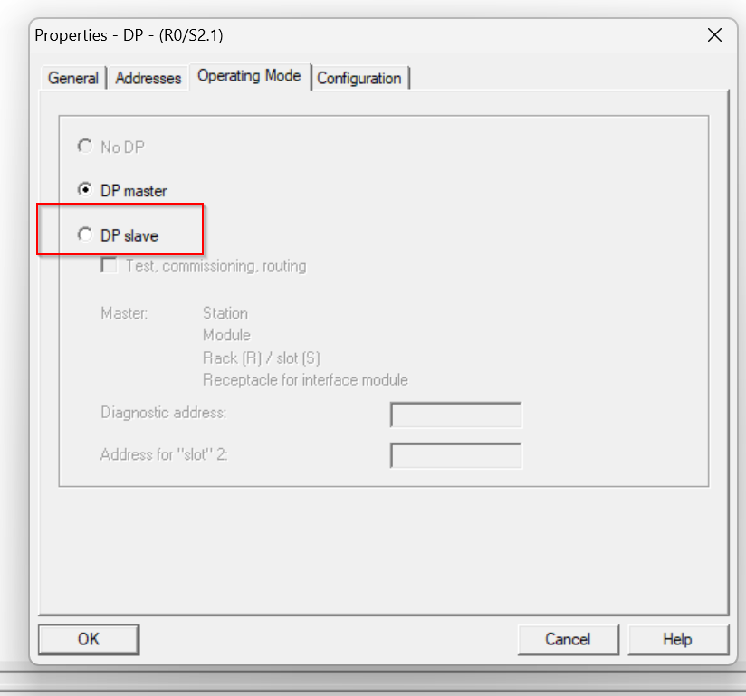
Done!
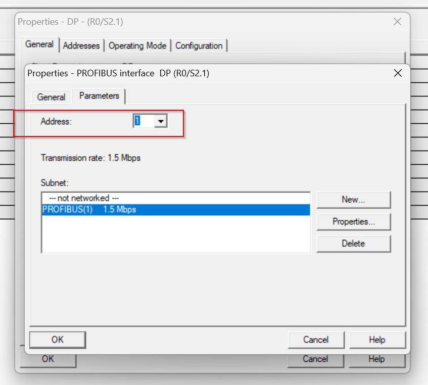
Node Address
Now the DP Port is running as a Slave, but we need to set the Profibus address.
Set the address of Profibus according to the application from the Address item in the Parameters Tab.
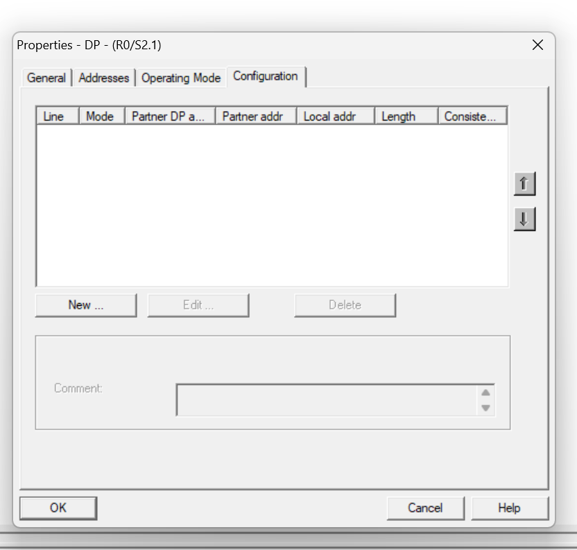
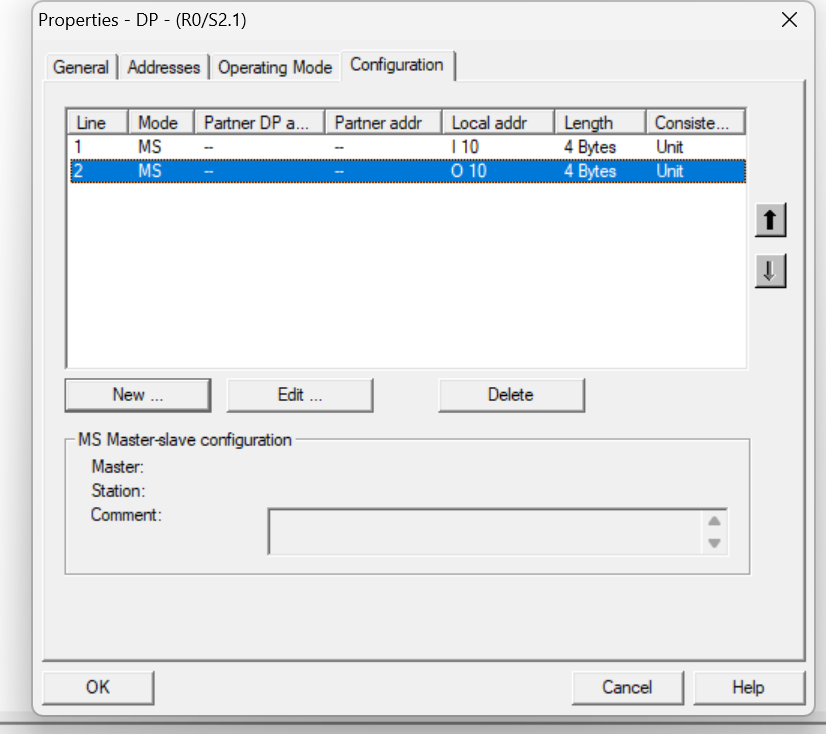
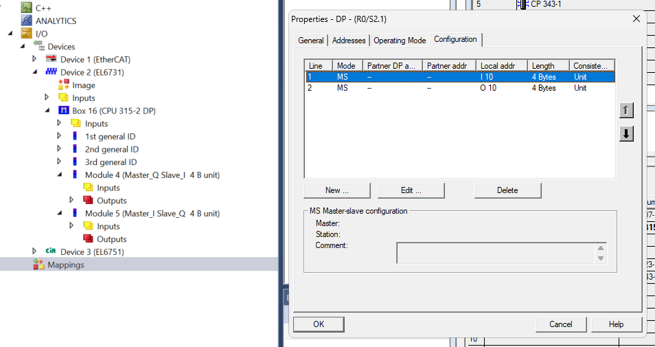
Configuration
Finally, open the Configuration Tab and define the data mapping to be exchanged between DP Slave and Master.The CPU 315-2 DP has no fixed slots, allowing the input/output memory area to be freely configured to suit the application.
Add Input Data
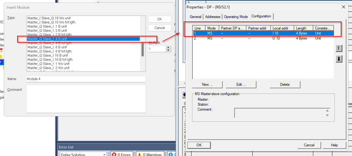
Click the New button to define a new data exchange area.
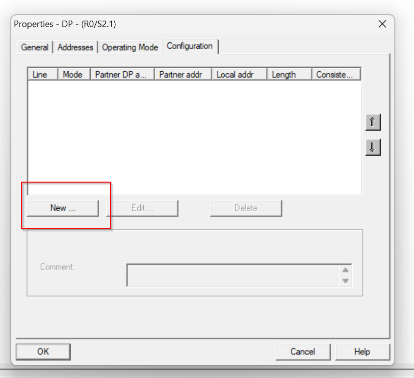
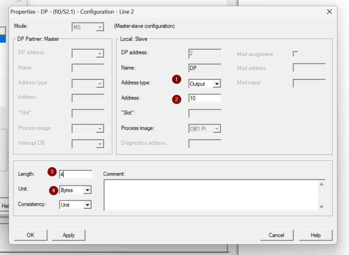
The Properties settings screen for the slot will appear.
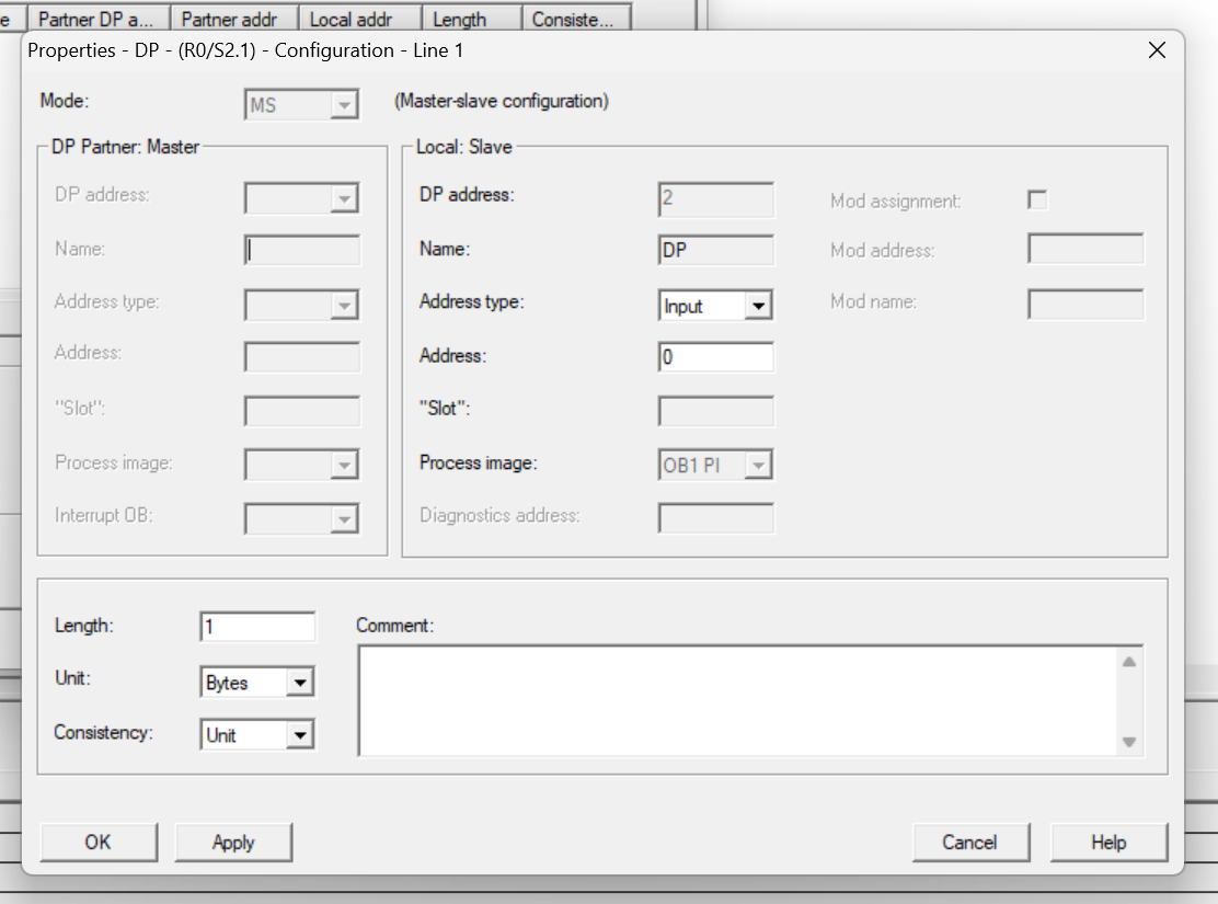
Address Type allows you to change the input or output of the currently set Slot. Address sets the address offset of the corresponding slot. (I=Input, Q=Output)
Length is the memory size of the corresponding Slot.
Unit is the data type of the corresponding Slot.
In the figure below, Slot is set as the input and Address starts with 10, for a total of 4 Bytes of input data.
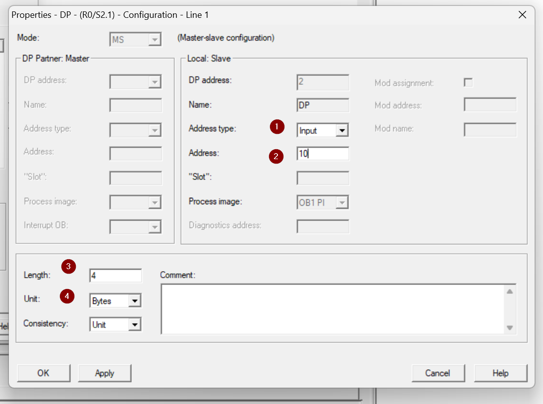
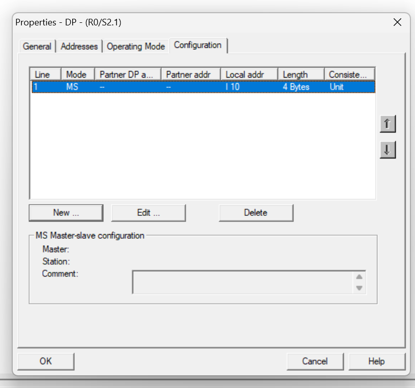
Done!Slot defined.
Add Output Data
Next, set the output data in the same way as before. This time, set the Address Type to “Output.
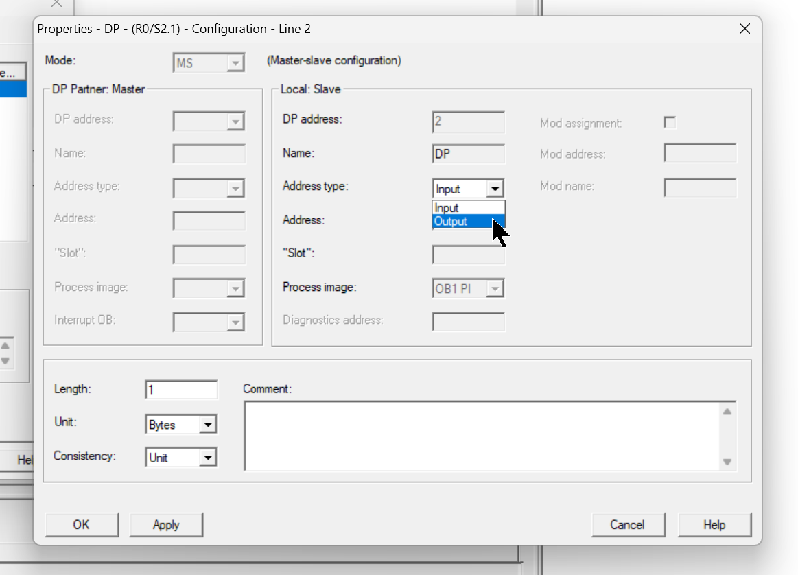
In the figure below, Slot is set as the input and Address starts with 10, resulting in a total of 4 Bytes of output data.
Done!
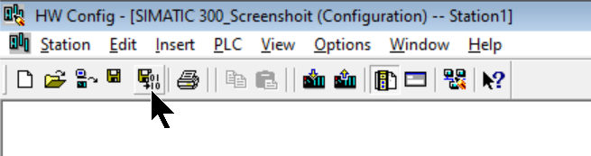
Save and Compile
Next, compile Hardware Configuration.
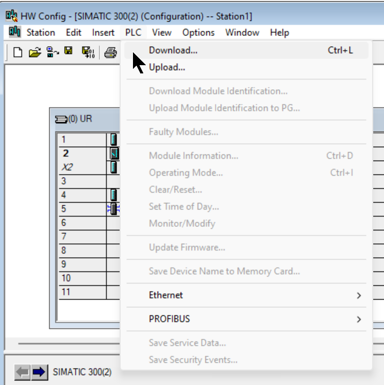
Download
Finally, use PLC>Download to download the Hardware Configuration to the CPU.
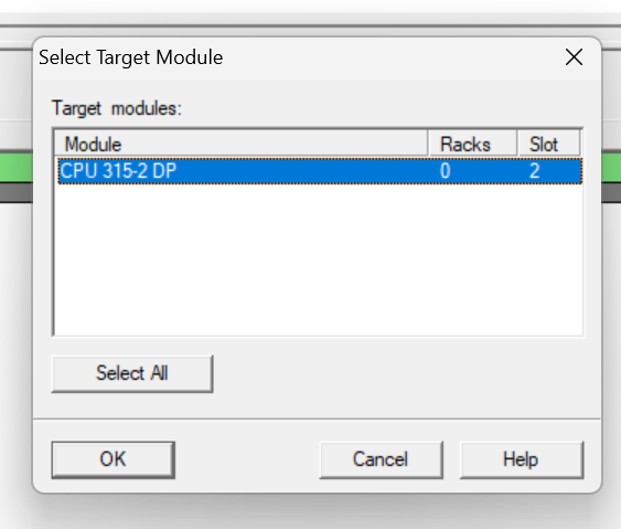
Select the CPU 315-2 DP used in this article and proceed with Ok.
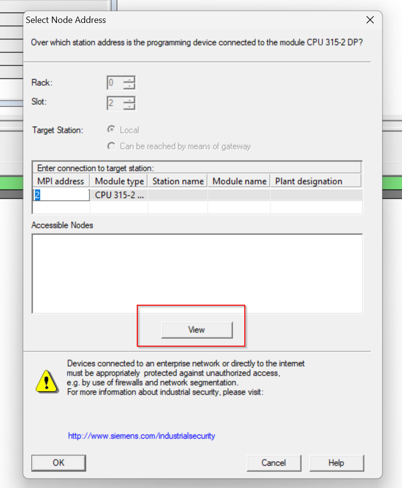
View searches for devices currently connected to the PC.
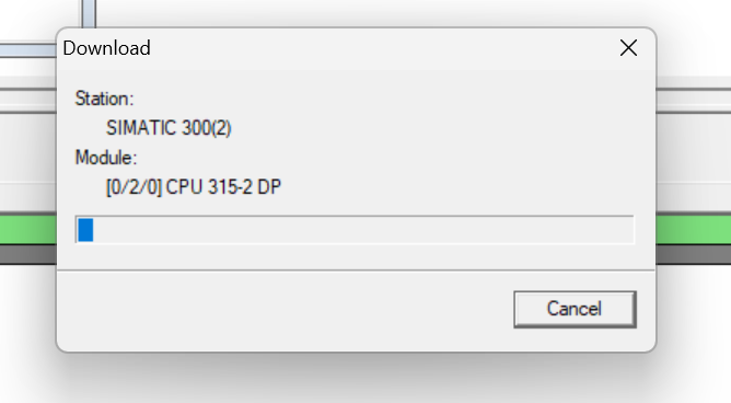
Done!CPU 315-2 DP is found, click OK and Download Hardware Configuration to CPU.

wait for a while…
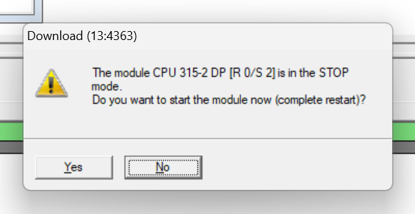
Done!The Yes button switches the CPU to Run Mode.
Beckhoff Side
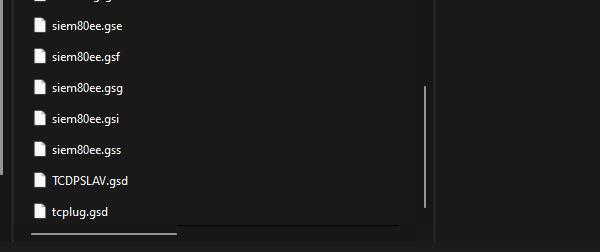
Install GSD File
Next is the TwinCAT3 side. Please store the GSD File you have just downloaded in the following Path.
C:\TwinCAT\3.1\Config\Io\Profibus
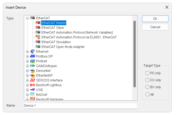
Add EtherCAT Master
I/O>Device>Right click>Add New Item.

Select EtherCAT>EtherCAT Master and proceed with OK.
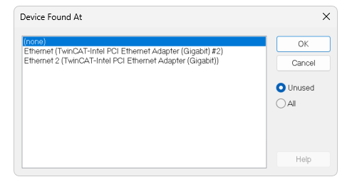
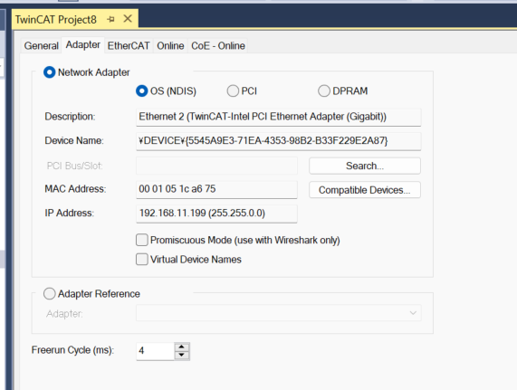
Configure the Ethernet Adapter that will be used as EtherCAT Master this time.
Done!
Scan EtherCAT Slave
Detect EtherCAT Slave using TwinCAT3’s automatic Slave detection. Right-click on the EtherCAT Master you have just added>Right-click>Scan.
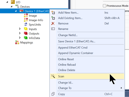
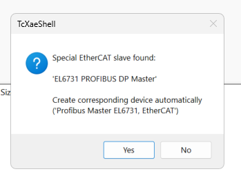
Done!EL6731 is found, proceed with Yes.
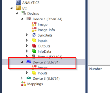
EL6731 has been added.
EL6731 Configuration
The next step is to configure the Profibus Terminal EL6731.
Term setting
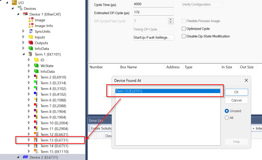
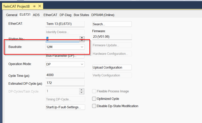
Open the EL6731 Settings page and click EL6731 Tab>Search.
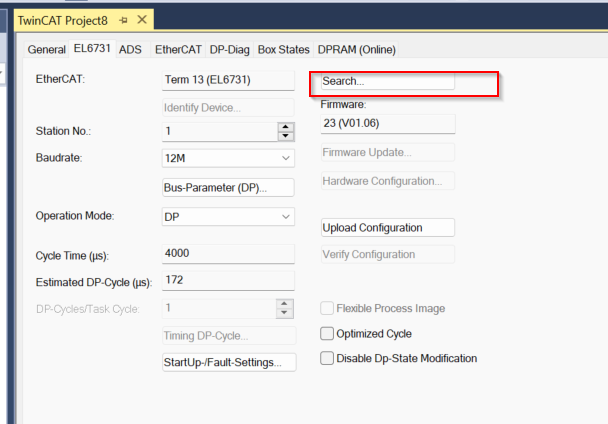
Please check that EL6731 is linked to the correct Terminal.
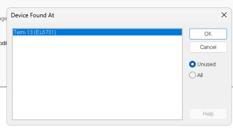
In the figure below, the EL6731 is shown as being in Terminal 13 because it is in Terminal 13.
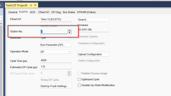
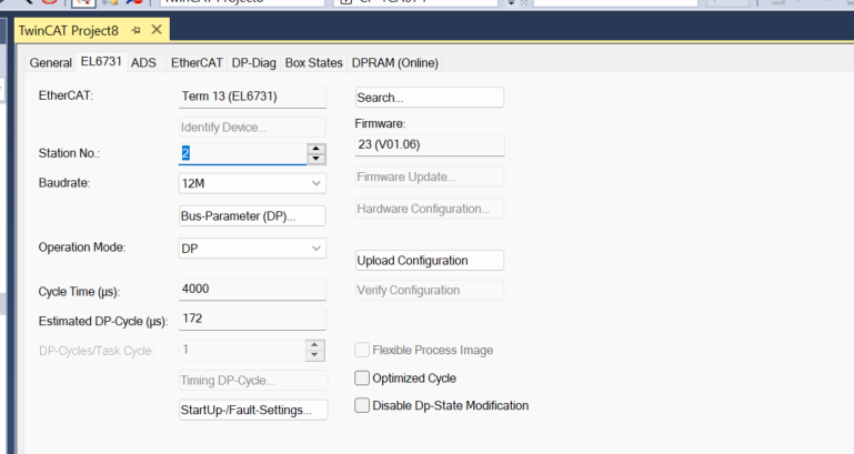
Station No
Next is the station number; Profibus, like CC-LINK and others, requires a unique number to be set up in the network.
This time, set the station number to 2 so that it will not be covered by the S7-300 Station.
Baudrate
Communication speed should also be consistent within the network.
Add Siemens Slave
After the Profibus Master has been set up, it is time to add the Siemens S7-CPU. Right click on EL6731>Add New Item.
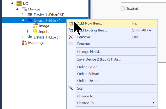
Select SIEMENS>CPU 315-2 DP and proceed with OK.

Done!

Station No
The station number should be the same as the number you have just set on the Siemens side.
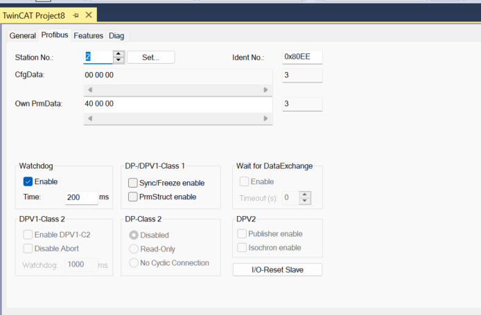
For this article, we will use 1.
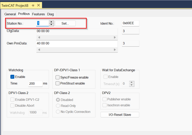
The first is actually the “1” set in Step 7 Classic.

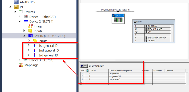
Slot
The next step is to set up each Slave in Slave.

Ignore the first Slave 1,2,3 as they are Siemens General IDs.
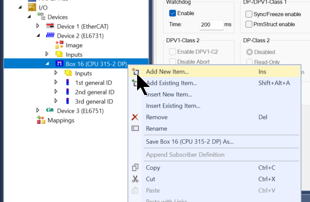
Add Slot4
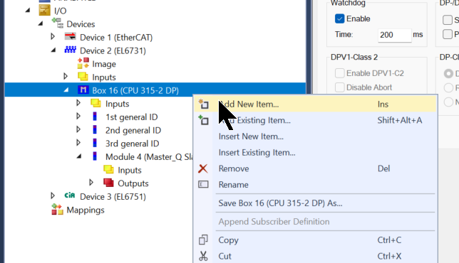
To add Slot 4, select Siemens CPU > right click > Add New Item.
Module List is displayed.
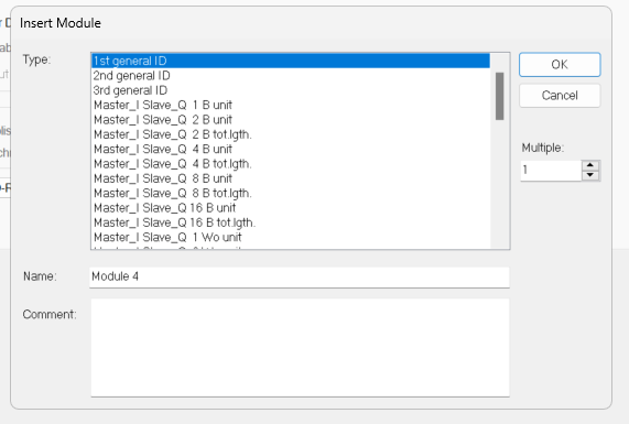
Select Master_Q_Slave_I_4 B Unit and proceed with OK.
Master_Q_Slave_I_4 B Unit to set, because Siemens side set that there is 4 Byte input data in Slot4.
Done!

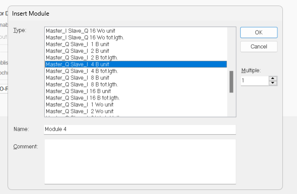
Add Slot5
To add Slot 5, select Siemens CPU > right click > Add New Item.
Master_Q_Slave_Q_4 B Unit to be set, because Siemens side has set that there is 4 Byte output data in Slot5.
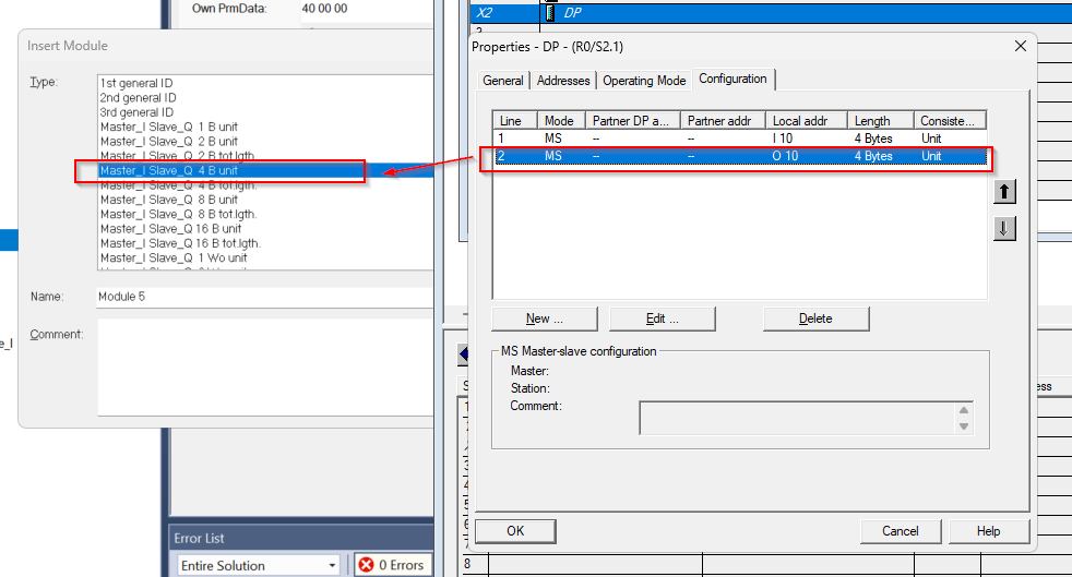
Done!This completes the setup.
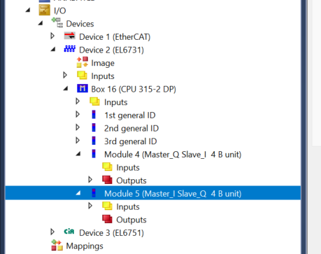
Result
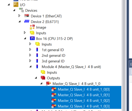
The actual EL6731 configuration results are shown below.
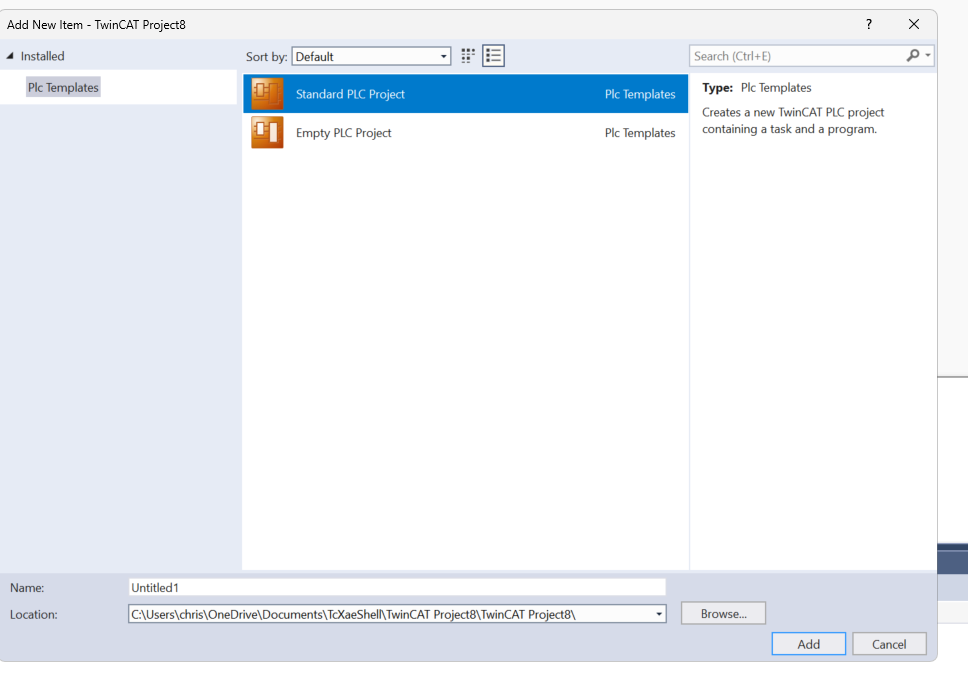
Add PLC
Now to add a PLC, go to PLC>Right Click>Add New Item.
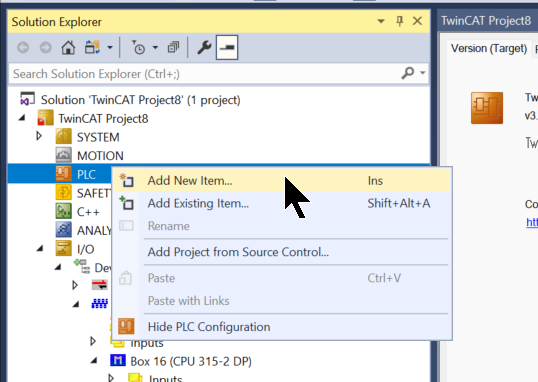
Select StandardPLC and proceed with Add.
Add GVL
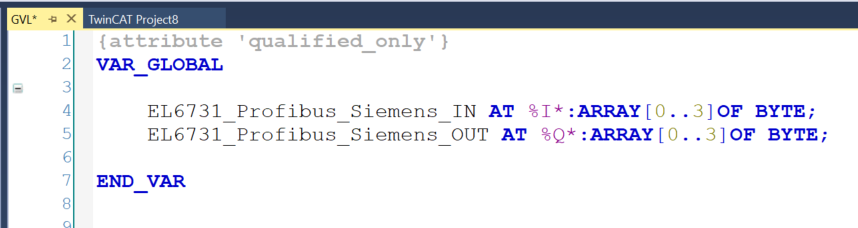
Add GVL to define variables to be Mapped to EL6731: GVL>Right click>Add>Global Variable List.
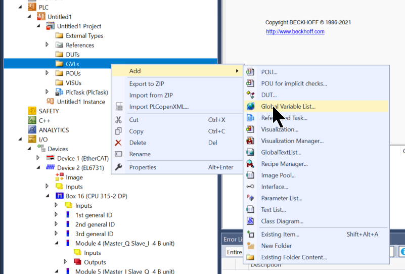
Define 4 Bytes of input and output data as shown in the figure below.
Build
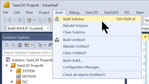
Compile the project under Build>Build Solution.
Mapping Output Data
Select all the Outputs in the Siemens CPU315 Slave that you added to the EL6731 > right click > Change Mulit Link.
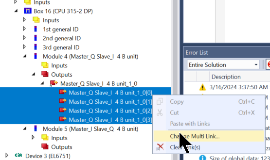
Select the output Process Data you defined earlier and press >Ok.

Done!
Mapping Input Data
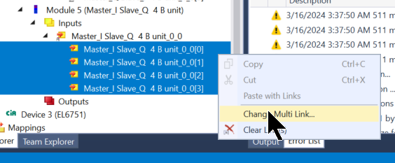
Select all Inputs in the Siemens CPU315 Slave that you added to the EL6731 > Right click > Change Multi Link.
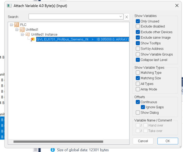
Select the input Process Data you defined earlier and press >Ok.
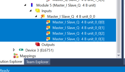
Done!
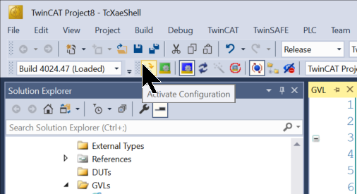
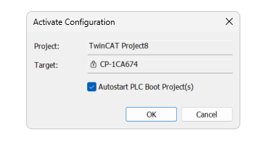
Activate Configuration
Click Activate Cofiguration to download the project to Runtime.
OK to proceed.
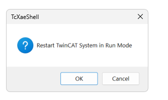
Switch Runtime to Run Mode.
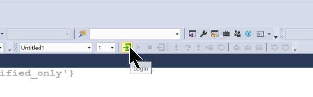
Login
Finally, login to Runtime.
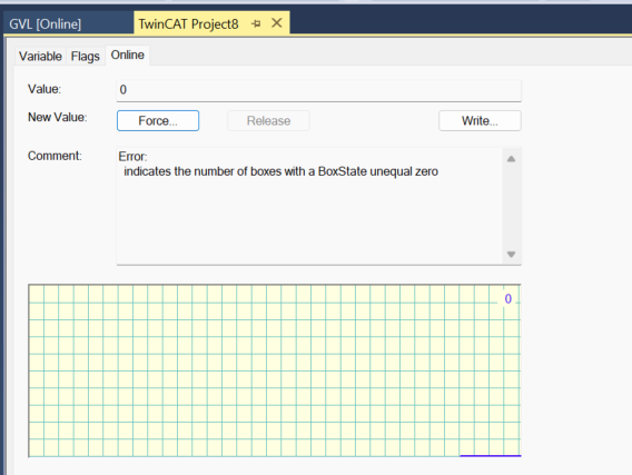
Result
Check the Error variable for EL6731.

The current value is 0, so there is no error.
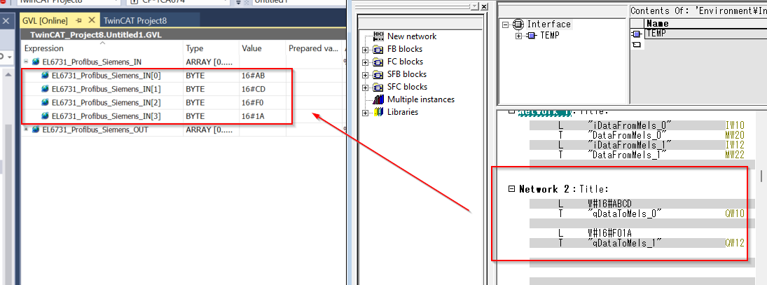
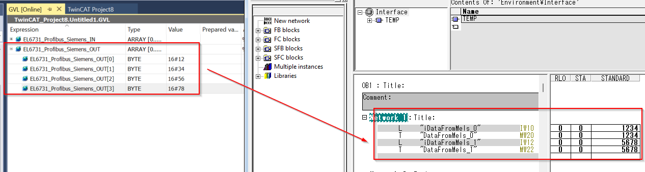
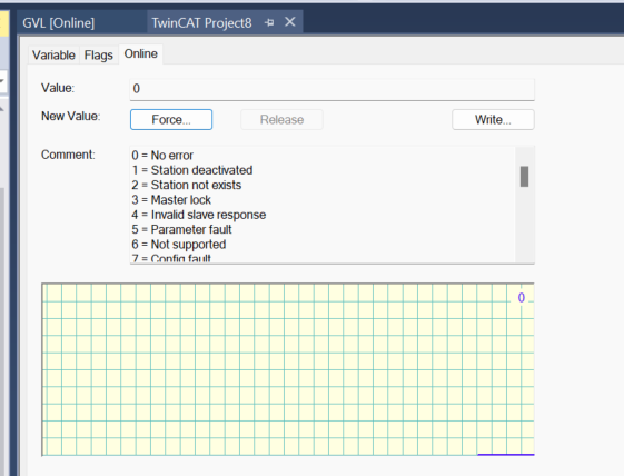
Now check the DpState on Siemens S7-315 in Slave.
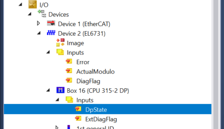
The current value is 0, so there is no error.
Both Siemens and Beckhoff were able to confirm inputs and outputs.