This is a new series from Berghof MC-PI, which uses the Safety PLC SC-1000 to verify and develop articles with various devices.First, we will start with the setup and start-up of the Codesys environment for using the SC-1000.
Come on, let’s enjoy FA.

Reference Link
http://soup01.com/en/category/berghof_en-en/
hint box
To use the SC-1000 on a Real application, you must confirm the correct Safety Package Version with Berghof before using it.
Foreword
Thank you from the bottom of my heart for visiting my technical blog and YouTube channel.
We are currently running the “Takahashi Chris” radio show with Full-san (full@桜 八重 (@fulhause) / X) which I deliver every Wednesday night.
Sharing, not hoarding, technical knowledge
We publish technical information related to factory production technology and control systems for free, through blogs and videos.
With the belief that “knowledge should be accessible to everyone,” we share practical know-how and real-world troubleshooting cases from our own field experience.
The reason we keep it all free is simple: to help reduce the number of people who struggle because they simply didn’t know.
If you’ve ever thought:
- “Will this PLC and device combination actually work?”
- “I’m having trouble with EtherCAT communication—can someone test it?”
- “I want to try this remote I/O, but we don’t have the testing environment in-house…”
Feel free to reach out!If lending equipment or sharing your configuration is possible, we’re happy to verify it and share the results through articles and videos.
(We can keep company/product names anonymous if requested.)
How can you support us?
Currently, our activities are nearly all unpaid, but creating articles and videos takes time and a proper testing environment.If you’d like to support us in continuing and expanding this content, your kind help would mean a lot.
Membership (Support our radio show)
This support plan is designed to enhance radio with Mr Full.
https://note.com/fulhause/membership/join
Amazon Gift List (equipment & books for content production)
Lists equipment and books required for content creation.
https://www.amazon.co.jp/hz/wishlist/ls/H7W3RRD7C5QG?ref_=wl_share
Patreon (Support articles & video creation)
Your small monthly support will help to improve the environment for writing and verifying articles.
https://www.patreon.com/user?u=84249391
Paypal
A little help goes a long way.
https://paypal.me/soup01threes?country.x=JP&locale.x=ja_JP
Just trying to share things that could’ve helped someone—if only they’d known.
Your support helps make knowledge sharing more open and sustainable.
Thank you for being with us.
soup01threes*gmail.com
Technical knowledge shouldn’t be kept to ourselves.
B-Nimis SC-1000?
B-Nimis SC-1000 is a BREGHOF safety PLC. The purpose of a safety PLC is to integrate functional safety functions into a control system.There is no need to provide a separate cable for safety circuits.The FS-PLC executes the safety application program and exchanges safety-related control information with the assigned safety slave module.
A prerequisite for using a safety PLC is the use of EtherCAT as fieldbus for data exchange with a CODESYS-based monitoring PLC.
Safety PLCs can integrate safety functions into control systems.The core of the Safety PLC consists of two microprocessors that implement safety functions, communicate with each other, exchange process data, and monitor each other.
A third microprocessor manages external communications.The modules can be installed in a row for integration into B-Nimis I/O systems.

The figure below shows an example of a control system using a safety PLC.When the system is running, process data is exchanged between the standard PLC and standard actuators and sensors.At the same time, the safety PLC exchanges safety-related signals with safety I/O modules and drives using the EtherCAT fieldbus and FSoE protocols.

B-Nimis I/O System
The B-Nimis SC-1000 used in this article, Safety PLC is a module within the B-Nimis I/O system.The B-Nimis I/O system is also a collection of I/O modules that can be stacked for integration into an EtherCAT network for process signal transmission.
The B-Nimis I/O bus coupler functions as a head module that converts the transmission from twisted pair to LVDS (E-bus) and generates the system voltage required by the LVDS module.It has a standard 100 base Tx line connected to one side.On the other side is a series of B-Nimis I/O modules for process signals.
Thus the EtherCAT protocol is retained until the last I/O module.Alternatively, a B-Nimis PLC can be used as head module instead of a bus coupler.In this case, it takes over the bus master function from the standard PLC.
B-Nimis-I/O Safety System
The B-Nimis-I/O Safety System extends the B-Nimis I/O system with a safety PLC and modules with safety inputs and outputs.The EtherCAT protocol is used to transfer both safety and standard signals to the safety PLC.

Safety PLC
The Safety PLC links the inputs and outputs of the B-Nimis-I/O safety system with the safety-related signals of other FSoE devices in the system.It then always works in conjunction with a CODESYS-based standard PLC.The FS-PLC is a 2-channel architecture and communicates with the programming system via logic exchange variables with the standard PLC and with the standard PLC using non-safety variables, inputs, and outputs.
CODESYS Safety
The safety PLC is based on certified plug-ins that are fully integrated into the CODESYS development system.The Safety PLC is programmed as an EtherCAT slave node under a standard PLC and provides a list of applications, tasks, global variables, POUs and logical I/Os.
- B-Nimis SC-1000 integration works only in combination with EtherCAT as a communication medium with the safety PLC.
- The integrated Function Diagram (FD) safety editor is used for programming at the basic or extended level.
- At the basic level, certified function blocks (PLCopen-Safety) are connected graphically and the safety program of the system is established.
- The software provides further functions to protect the safety functions, such as change tracking, safe signal flow, safe versioning (pinning), safe operation isolation, debug mode, etc.

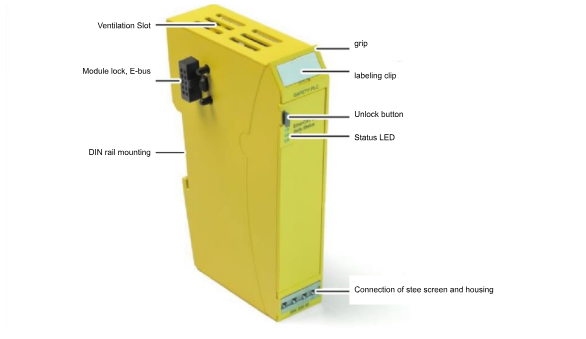
layout
Here is the Layout diagram for B-Nimis SC-1000.
B-Nimis SC-I/O S-DI4 S-DO2
The B-Nimis SC-IO S-DI4 S-DO2 safety module allows the connection of common safety devices and can be installed at any position in the B-Nimis I/O block.The signals are sent via the EtherCAT bus to the B-Nimis SC-1000 safety PLC, where they are processed in a safe manner.The outputs of the module can be safely integrated into circuits with actuators such as contactors, signal lamps or servo converters.

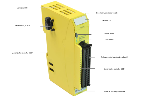
layout
This is a Layout for B-Nimis SC-I/O S-DI4 S-DO2.
FSoE address setting
The B-Nimis SC-I/O S-DI4 S-DO2 safety module operates with a security module address (FSoE slave address) that can be clearly identified within the safety communication network.The address is manually set via a binary switch on the left side of the module.
To set the FSoE address, use 2x 8 DIP switches.The address range is 1 to 65535 After setting the FSoE address, power off the B-Nimis SC-I/O S-DI4 S-DO2 safety module once and verify that the address is accepted and the module test is automatically started.
Multiple modules in a row make the DIP switches inaccessible; to set the FSoE slave address with the DIP switches, first remove the module from the module row.

Implementation
Firmware Update
First, update the MC-PI you have on hand to the latest Firmware.
Codesys version
The Codesys Version used in this article is V3.5.20 SP4.
Install CODESYS Safety Extension
To use the B-Nimis SC-1000, the Safety Extension must be installed; start Codesys and click Tools>CODESYS Installer.

Search for CODESYS Safety Extension from the Browse Tab.

Next, click the Install button.

OK to proceed.

Accept the license and proceed with Continue.

It is necessary to close CODESYS to install Packages.

Please wait a moment…

Done!

ES File Installation
Next, click on Tools>Device Respository to install the ESI FILE for B-Nimis SC-1000 and B-Nimis SC-I/O S-DI4 S-DO2.

Click the Install button.

Select the ESI FILE you received from Berghof.

Create a new project
Create a new project at File>New Project.

Select Standard project >Ok to proceed.

Select Target
Next, let’s set the device Target to be used for the Codesys project.

Now that you have installed BERGHOF’s Target from the previous step, select BERGHOF MC-PI SoftMotion Control for Device > Ok to proceed.

Done!A new Codesys project has been created.

scan network
Next, go to Device>Scan Network and search for BERGHOF’s Controller.

Library Installation
Next, click on Library Manager to install Berghof’s libraries.

Click on Library Repository.

Install the library that Berghof gave us.

Configuring an EtherCAT network
We are now going to build an EtherCAT network for MC-PI.
Addition of EtherCAT Master
To add an EtherCAT master, go to Device>Right click>Add Device.

Select Fieldbus>EthereCAT>Master>EtherCAT Master and add with Add Device.

Done!

Source address settings
To configure the Ethernet interface to operate as an EtherCAT master, click on the master you have just added and click on General>Select.

Lists the Ethenret interfaces currently on the actual device.

Eth1 is used in this article.

scan network
Click on Scan for Device to search for slaves in the EtherCAT network.

If ESI FILE is not installed, a Not Found message will appear as shown below.

Done!I was able to find B-Nimis SC-1000 and B-Nimis SC-I/O S-DI4 S-DO2, but I need to change the settings manually here, because with EtherCAT network SCAN, SC_1000 may not be added as a Safety PLC.In that case, click on SC_1000.

The Device Description selection screen appears.

Choose PLCs>Safety PLCs>B-Nims SC 1000.

Done!

Finally, select onboard_buskoppler and use “Copy to project” to duplicate all the Slaves to the Hardware Configuration.

Done!

FSoE address settings
To match the FSoE address of the B-Nimis SC-I/O S-DI4 S-DO2 to the actual device, click Safey App>Logical I/Os>Connecting B-Nimis SC-I/O S-DI4 S-DO2.

The Safe configuration screen appears.

Match the FSoE Address to the DIP switch on the actual device and make sure that the connection ID does not overlap with other FSoE devices.

I set both the FSoE address and the Conntion ID to 3 in this article.

Input Parameters
The B-Nimis SC-I/O S-DI4 S-DO2 allows the use or disuse of safety inputs in the Input parameters section.Since the purpose of this article is to illustrate the process of making a connection, we will disable all safety inputs for now.In this case, select “Not Input used”.

Output Parameters
The B-Nimis SC-I/O S-DI4 S-DO2 allows you to set the use or disuse of safety outputs in the Input parameters section of the B-Nimis SC-I/O S-DI4 S-DO2.Since the purpose of this article is to illustrate how the connection can be made, we will disable all safety outputs for now.In this case, select “Not Output used”.

Connect to CPU
Next, let’s connect the Codesys CPU to the PC.

Log in to non-safe PLC
Download your project to the CPU with Login.

Let’s proceed with Yes!

Non-safety PLC Start
Finally, press the Start button to set Runtime to Run.

Addition of safety POUs
Next, to add a program to the Safety PLC, click Safety PLC>right click>Add Object>Basic POU(Safety).

Enter a Safety POU name and add a new Safety POU.

Done!

Confirmation of safety tasks
The Safety POU you just added is automatically added to the Safety Task.

Done!

Safety PLC Login
Select Safety App from the drop-list to Login the safety program to the safety PLC.

Loginボタンをクリックします。

To Login to SC-1000, the serial number of the module is required.

The serial number is printed on the body of the SC-1000.

Enter the number shown in the red box earlier.

Next, you can choose to temporarily download the safety application or generate it as a boot application.

Since we want to use it as a boot application for this article, let’s click on the red frame in the figure below.

You will be asked to enter a password for the Safety PLC, and since there is no password on the Default, leave it blank and click OK.

Proceed with Yes.

Done!

Safety PLC Start
Finally, the Runtime of the Safety PLC should also be in Run mode.

Done!

We also want to check the communication status of the safety IOB-Nimis SC-I/O S-DI4 S-DO2, so click on the B-Nimis SC-I/O S-DI4 S-DO2 module.

The FSoE Address in Safety Diagnostics was recognized!

There is no error information in the Log.

Load safe boot application
The last step is to load the safety application as the boot application.Logout from the Safety PLC once first.

Proceed with Yes.

OK to proceed.

Done!The Safety application has been restarted as a boot application.

SAFETY PLC status also changed to DEBUG>SAFE.


The EtherCAT Run/Safe Status on the module itself is now also lit green!
