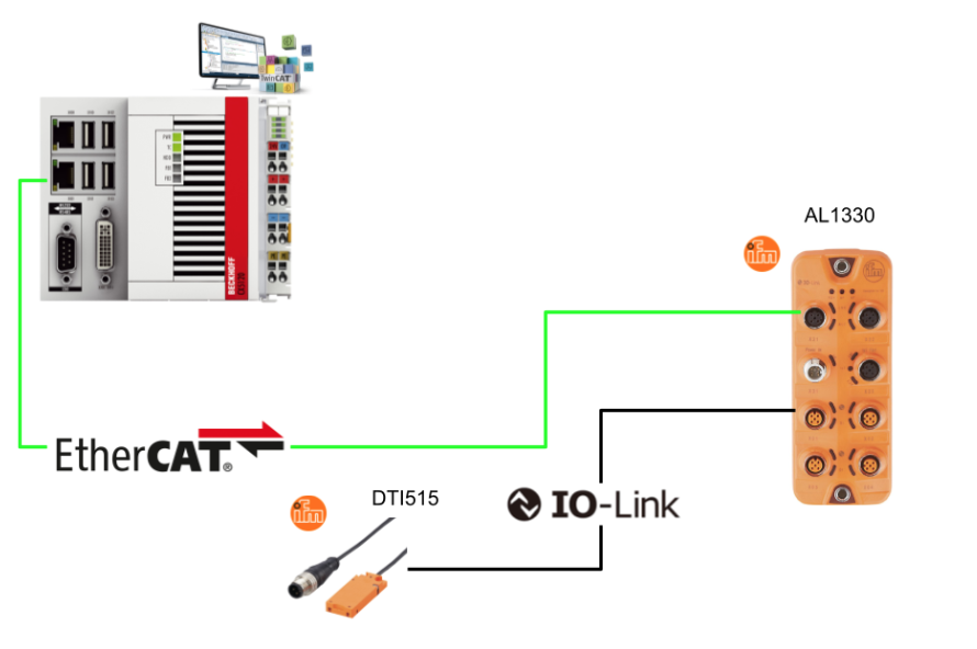
In this article, we will implement the control of UID reading and automatic data writing from the Beckhoff TwinCAT environment using an IO-Link compatible RFID reader (DT1515) from IFM.It utilises originally defined FBs and carefully explains how to use Read UID mode and Auto Read/Write mode, as well as the key points of Cmd control, status determination and process data structure.
Come on, let’s enjoy FA.
Foreword
Thank you from the bottom of my heart for visiting my technical blog and YouTube channel.
We are currently running the “Takahashi Chris” radio show with Full-san (full@桜 八重 (@fulhause) / X) which I deliver every Wednesday night.
Sharing, not hoarding, technical knowledge
We publish technical information related to factory production technology and control systems for free, through blogs and videos.
With the belief that “knowledge should be accessible to everyone,” we share practical know-how and real-world troubleshooting cases from our own field experience.
The reason we keep it all free is simple: to help reduce the number of people who struggle because they simply didn’t know.
If you’ve ever thought:
- “Will this PLC and device combination actually work?”
- “I’m having trouble with EtherCAT communication—can someone test it?”
- “I want to try this remote I/O, but we don’t have the testing environment in-house…”
Feel free to reach out!If lending equipment or sharing your configuration is possible, we’re happy to verify it and share the results through articles and videos.
(We can keep company/product names anonymous if requested.)
How can you support us?
Currently, our activities are nearly all unpaid, but creating articles and videos takes time and a proper testing environment.If you’d like to support us in continuing and expanding this content, your kind help would mean a lot.
Membership (Support our radio show)
This support plan is designed to enhance radio with Mr Full.
https://note.com/fulhause/membership/join
Amazon Gift List (equipment & books for content production)
Lists equipment and books required for content creation.
https://www.amazon.co.jp/hz/wishlist/ls/H7W3RRD7C5QG?ref_=wl_share
Patreon (Support articles & video creation)
Your small monthly support will help to improve the environment for writing and verifying articles.
https://www.patreon.com/user?u=84249391
Paypal
A little help goes a long way.
https://paypal.me/soup01threes?country.x=JP&locale.x=ja_JP
Just trying to share things that could’ve helped someone—if only they’d known.
Your support helps make knowledge sharing more open and sustainable.
Thank you for being with us.
soup01threes*gmail.com
Technical knowledge shouldn’t be kept to ourselves.
Reference Link
RFID read/write head HF DTI515
IFM’s DT1515 reliably identifies ID tags on workpieces and products RFID HF read/write head Flat design for applications with limited mounting space High degree of protection for the requirements of harsh industrial environments Suitable for use with RFID antenna adapters, extending the range Available with.

purpose of use
- The read/write head reads and writes ID tags contactlessly.
- The data is available as process data via the IO-Link interface.
ID tags
ID tags operate passively without batteries; the energy required for operation is supplied by the read/write head; supports ISO 15693-compliant ID tags.
Sensing Face
This is the RFID detection area of the DT1515.

Status bit
This is the Process input/output data Mapping for DT1515.

input data
| bit name | Value | Description. |
| Antenna deactivated | 0 | Antenna enabled and ready for reception. |
| 1 | Antenna disabled/reception disabled | |
| Tag present | 0 | untagged |
| 1 | Tagged (RFID tag detected) | |
| Cmd End | 0 | Read/write process has not yet started or is running |
| 1 | Read/write process completed. | |
| Cmd Start Acknowledge | 0 | Start of reading and writing not yet ACKed |
| 1 | Device has recognised the start of a read/write operation (ACK received) |
output (data)
| bit name | Value | Description. |
| Cmd Antenna deactivate | 0 | Antenna enabled (normal state) |
| 1 | Antenna deactivation (stops RFID communication). | |
| Cmd Start | 0 | Reset state (read/write not performed) |
| 1 | Trigger state (to initiate read/write) |
operating mode
Here are the command mode specifications for ifm RFID devices (e.g. DT1515) and a description of how each works.
| command name | Value (Hex) | operation details | Remarks |
| Read UID | 0x00 | Read the UID of the tag. | default |
| Auto-read data | 0x01 | Automatic reading of data in tags | |
| Auto-write data | 0x02 | Automatic writing of data to tags. | |
| Read data | 0x03 | Explicitly read the data. | |
| Write data | 0x04 | Write data explicitly |
Operating mode Read UID
‘Read UID’ mode is the basic operating mode for the IFM RFID reader to read the UID (unique ID) of an ID tag. When this mode is enabled, the UID is automatically transferred to the **Input Process Data** area when the tag enters the reader’s communication range.
If no tag is detected, the byte in which the UID is stored (usually arrIn[2] to arrIn[6] etc.) will contain 0x00, indicating a ‘no tag’ status.
Once the UID is detected, the device maintains it for a certain period of time (data hold time) to continue the transfer. If another tag enters the communication range during this time, the UID of the new tag is automatically updated to the UID of the new tag and the transfer is switched.
This mode operates as the default setting at device start-up and allows for immediate tag UID reading without having to send special commands.

Operation mode Auto read data
In ‘Auto Read Data’ mode, the data in the memory area of the ID tag is automatically read and stored in the process data input area (input image). The specified data is also stored in the input area and the remaining bytes are filled with 0x00.

Operation mode Auto write data
The ‘Auto Write Data’ mode is an operating mode for automatic writing of data to ID tags: write data is stored in the output image (Process Data Output Image) from a PLC or similar, and writing starts automatically as soon as the tag enters the detection range of the device. The tag is automatically written as soon as it enters the detection range of the device.
A maximum of 28 bytes of data stored in bytes 0 to 27 of the output image is written.
If the data length is less than 28 bytes, the remaining bytes are ignored and will not be written to the tag.

BYTE_TO_HEXSTR
This function converts a decimal number to a hexadecimal string (base 16).

VAR_IN
| Variable Name | Data type | Description |
| in | BYTE | Decimal number to be converted |
| iPrecision | INT | minimum number of trusses |
| bLoCase | BOOL | Determines whether lower or upper case letters are used for conversion; FALSE => “ABCDEF”, TRUE => “abcdef”. |
BYTE_TO_HEXSTR 2: Return value
| variable name | data type | Description. |
| BYTE_TO_HEXSTR | T_MaxString | Conversion Result |
Implementation
Beckhoff Side
Now let’s actually build the project.

Download ESI files
In order to use an EtherCAT slave device with TwinCAT, an ESI file (EtherCAT Slave Information) for the device is required. Download the ESI file for AL1330 from the IFM website.

The one used in this article is 4024, so please store the downloaded ESI file in the following Directory.
| C:\TwinCAT\3.1\Config\Io\EtherCAT\ |

Adding new devices
New I/O devices (e.g. EtherCAT Master) can be added manually by right-clicking in the “I/O” tree of the TwinCAT project and selecting “Add New Item…” from the context menu.

Select ‘Add New Item…’ to open the ‘Insert Device’ window.
Here you can select the type of device to be added. In this case, select EtherCAT → EtherCAT Master as we are using Beckhoff’s EL6631-0010. This setting adds an EtherCAT Master device in the TwinCAT project to which the EL6631-0010 (PROFINET Device) can be connected as a slave.

When you add an EtherCAT Master, it automatically searches for EtherCAT devices on the PC and displays the ‘Device Found At’ dialogue.
Here you can select the found EtherCAT communication card or virtual device from the list and specify the slot to be used.
For example:
- X001 (X001) and X000 (X000) refer to devices such as on-board adapters
- PCI Bus/Slot 3/0, Slot 7 (0x91620000) refers to devices such as communication cards connected to PCIe slots.

This time PCI Bus/Slot 3/0, Slot 7 (0x91620000): specifies a real EtherCAT communication card mounted in a PCI slot.

After the EtherCAT master has been added and allocated, the master configuration appears as ‘Device 1 (EtherCAT)’ under ‘I/O → Devices’ in the TwinCAT project.

auto scan
Right-click on the EtherCAT master (Device 1) and in the menu that appears you will find “Scan”. By clicking on this “Scan”, TwinCAT will automatically detect the actual connected EtherCAT slave devices and add them to the configuration. This function is very useful when several I/O terminals or communication modules are connected to the EtherCAT line and can be captured in the exact E-Bus order of the devices.

AL 1330 shown.

When AL1330 is scanned, Modules 1 to 4 are displayed below it. This corresponds to each port of the IO-Link master and indicates that 4 bytes of IN/OUT communication area is available on each port (= IOL_4/4_I/O-Bytes).

Slot
The ‘Slots’ tab shows the slot configuration for each IO-Link channel. By default, all channels (Ch.1 to Ch.4) are initially configured as IOL_4/4_I/O-Bytes modules (4 bytes IN / 4 bytes OUT). This configuration is suitable for devices with binary or small-scale data communication, e.g. RFID and small sensors.

By default, each IO-Link channel of the AL1330 is configured as IOL_4/4_I/O-Bytes (4 bytes IN, 4 bytes OUT), but if you want to exchange larger data (e.g. when using RFID tags in this article), the configuration can be manually changed Possible.

In this example, the ‘IOL_32/32_I/O-Bytes’ module is configured in IO-Link Ch.1, which enables 32-byte process data communication.

Addition of PLCs
After all the I/O and PROFINET configuration has been completed, you can proceed to add the PLC control programme: right-click on the PLC > Add New Item.

In the ‘Add New Item’ screen, select the PLC project template to be used in TwinCAT: select Standard PLC Project and proceed with >Add.

ITF_IFMDT1515
PROPERTY AntennaDeactivated : BOOL -GET
Checking the condition of the antenna
PROPERTY AntennaDeactivated : BOOL -SET
Antenna on/off control
PROPERTY AutoWriteStr : STRING-GET
Get data for writing.
PROPERTY AutoWriteStr : STRING-SET
Set data for writing.
PROPERTY Tagpresent : BOOL-GET
Check if the tag has been detected.
METHOD AutoRead : STRING
Perform an automatic read (return the result as a string).
METHOD AutoWrite : BOOL
Perform automatic write, TRUE if successful
METHOD ReadUID : STRING
Read only the UID (apart from AutoRead).
fbIFMDT1515
Defines the FB for reading IFM’s DT1515.
| FUNCTION_BLOCK fbIFMDT1515 IMPLEMENTS ITF_IFMDT1515 VAR_INPUT END_VAR VAR_OUTPUT END_VAR VAR arrIn AT %I*:ARRAY[0..31]OF BYTE; arrOut AT %Q*:ARRAY[0..31]OF BYTE; strUID:STRING; strAutoWrite: STRING(20); strAutoRead :STRING(20); strWrite: STRING(20); strRead :STRING(20); iCounter :INT; iStatus,iCmd :BYTE; iStatus2,iCmd2 :BYTE; END_VAR |
PROPERTY AntennaDeactivated : BOOL -GET
This property is used to obtain the enable/disable status of the built-in antenna of the IO-Link RFID reader (DTI515/DTI516).
| AntennaDeactivated:=arrIn[1].3; |
PROPERTY AntennaDeactivated : BOOL -SET
This property is used to control the enable/disable of the built-in antenna of the IO-Link RFID reader (DTI515/DTI516). Set the specified Boolean value for **bit 3 (0x08)** in Byte 2 of the output process data.
| arrOut[2].3:=AntennaDeactivated; |
PROPERTY AutoWriteStr : STRING-GET
This property is used to obtain the write data (string) used for automatic writing to the RFID tag.
| AutoWriteStr:=strAutoWrite; |
PROPERTY AutoWriteStr : STRING-SET
This property is used to set the write data (string) for automatic writing to the RFID tag. The string AutoWriteStr received externally is stored in the internal variable strAutoWrite.
| strAutoWrite:=AutoWriteStr; |
PROPERTY Tagpresent : BOOL-GET
This property is used to check whether a tag is present within the read range of the RFID reader (DTI515/DTI516).
| Tagpresent:=arrIn[1].2; |
METHOD AutoRead : STRING
This method implements the process of automatically reading the data stored in the RFID tag via IO-Link and returning it as a string.
- Read is executed when xExe is TRUE.
- Sends command 0x01 (Auto Read Data) to the device according to arrOut[0] := 1.
- Copy Byte 2 onwards (arrIn[2]~) of the input process data to strAutoRead.
- The result is returned as an AutoRead return value.
Tc2_System.MemCpy() is used for the copy process,
MemCpy(), which is a function for storing the byte sequence (data from the RFID tag) directly into a variable of type STRING in the PLC.
| METHOD AutoRead : STRING VAR_INPUT xExe : BOOL; END_VAR IF xExe THEN arrout[0]:=1; strAutoRead:=”; Tc2_System.MemCpy( destAddr:=ADR(strAutoRead) ,srcAddr:=ADR(arrIn[2]) ,n:=SIZEOF(strAutoRead) ); AutoRead:=strAutoRead; END_IF |
METHOD AutoWrite : BOOL
This method processes the string data (strAutoWrite) held in the PLC and automatically writes it to the RFID tag via IO-Link.
- The write operation is executed when xExe is TRUE.
- Send command 0x02 (Auto Write Data) to the device according to arrOut[0] := 2
- The character string to be written (strAutoWrite) is transferred to arrOut[2] or later (max. 28 bytes)
- Writing is automatically performed when the tag is within the read range.
- MemCpy() copies the contents of the STRING type as a byte string directly to the output array.
| METHOD AutoWrite : BOOL VAR_INPUT xExe : BOOL; END_VAR IF xExe THEN arrOut[0]:=2; Tc2_System.MemCpy( destAddr:=ADR(arrOut[2]) ,srcAddr:=ADR(strAutoWrite) ,n:=SIZEOF(strAutoWrite) ); END_IF; |
METHOD ReadUID : STRING
This method is used to read the **UID (unique identification number)** of an RFID tag and return it in hexadecimal string format. It can be used as a starting point for identification and traceability using tag-specific information.
- When xExe = TRUE, command 0x00 (Read UID) is sent to the device.
- Read the UIDs (8 bytes) stored in Byte 2 to Byte 9 of the input data in sequence.
- Convert each byte to hexadecimal 2-digit notation with BYTE_TO_HEXSTR().
- The converted strings are concatenated as strUID and returned as the return value.
| METHOD ReadUID : STRING VAR_INPUT xExe : BOOL; END_VAR IF xExe THEN arrOut[0]:=0; strUID:=”; FOR iCounter:=2 TO 9 DO strUID:=CONCAT( STR1:=strUID ,STR2:= BYTE_TO_HEXSTR(in:=arrIn[iCounter],iPrecision:=2,bLoCase:=FALSE) ); END_FOR ReadUID:=strUID; END_IF; |
MAIN
In the MAIN programme, one fbIFMDT1515 (FB for IO-Link RFID access) is instantiated and three operation modes (UID read / auto read / auto write) are exclusively selected for processing execution.
| PROGRAM MAIN VAR fbIFMDT1515_1:fbIFMDT1515; xReadUID,xAutoRead,xAutoWrite:BOOL; strUID,strAutoRead,strAutoWrite:STRING; END_VAR strUID:= fbIFMDT1515_1.ReadUID(xExe:=xReadUID AND NOT xAutoRead AND NOT xAutoWrite); strAutoRead:= fbIFMDT1515_1.AutoRead(xExe:=xAutoRead AND NOT xReadUID AND NOT xAutoWrite); fbIFMDT1515_1.AutoWriteStr:=strAutoWrite; fbIFMDT1515_1.AutoWrite(xExe:=xAutoWrite AND NOT xAutoRead AND NOT xReadUID); |
Link
Mapping input data.

The input data from the EtherCAT slave device (here ifm AL1330) is stored in TxPDO input bytes 0 to 31 and reaches TwinCAT.
- Open Module 1 > TxPDO and select all input byte 0 to input byte 31.
- Right-click → ‘Change Multi Link…’. Select
- In the window that appears, specify MAIN.fbIFMDT1515_1.arrIn

Mapping output data.

The data output from the fbIFMDT151515 via EtherCAT is sent to the slave side via TwinCAT output bytes 0 to 31. Linking these output data to arrOut[0] to arrOut[31] inside the FB ensures that the commands from the PLC programme reach the device correctly.
- Select all output bytes 0 to 31 in Module 1 > RxPDO (or TxPDO reverse).
- Right-click → “Change Multi Link…” Select
- Specify MAIN.fbIFMDT1515_1.arrOut

Result
At this timing, only the ReadUID() process was executed and UID E0040150E4 was read.

In this state, the data ‘1234444’ in the tag was successfully read.
Successful reads were observed with AutoRead() flag control functioning and exclusively with ReadUID() and AutoWrite() disabled.

The AutoWrite() execution correctly copied the specified ‘abcdfff’ to the output buffer arrOut and sent it to the device via IO-Link communication.

The information I had just written down reads.

Download
Download the project for this article at this Link.
https://github.com/soup01Threes/TwinCAT3/blob/main/TwinCAT_IFM_AL1330_DT1515.tnzip