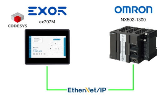
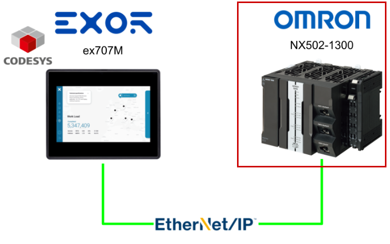
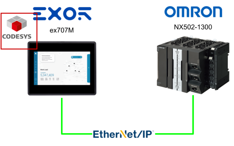
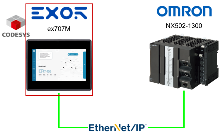
This article describes how the Codesys Runtime installed on the EXOR ex707M communicates with OMRON’s NX502-1300 via Ethernet/IP. It exchanges data at a 1ms cycle and saves data to the Codesys internal memory at a 10ms cycle.
The saved data is then displayed using the EXOR JMobile Scatter Diagram.
Alright, let’s enjoy the FA!
Foreword
Thank you from the bottom of my heart for visiting my technical blog and YouTube channel.
We are currently running the “Takahashi Chris” radio show with Full-san (full@桜 八重 (@fulhause) / X) which I deliver every Wednesday night.
Sharing, not hoarding, technical knowledge
We publish technical information related to factory production technology and control systems for free, through blogs and videos.
With the belief that “knowledge should be accessible to everyone,” we share practical know-how and real-world troubleshooting cases from our own field experience.
The reason we keep it all free is simple: to help reduce the number of people who struggle because they simply didn’t know.
If you’ve ever thought:
- “Will this PLC and device combination actually work?”
- “I’m having trouble with EtherCAT communication—can someone test it?”
- “I want to try this remote I/O, but we don’t have the testing environment in-house…”
Feel free to reach out!If lending equipment or sharing your configuration is possible, we’re happy to verify it and share the results through articles and videos.
(We can keep company/product names anonymous if requested.)
How can you support us?
Currently, our activities are nearly all unpaid, but creating articles and videos takes time and a proper testing environment.If you’d like to support us in continuing and expanding this content, your kind help would mean a lot.
Membership (Support our radio show)
This support plan is designed to enhance radio with Mr Full.
https://note.com/fulhause/membership/join
Amazon Gift List (equipment & books for content production)
Lists equipment and books required for content creation.
https://www.amazon.co.jp/hz/wishlist/ls/H7W3RRD7C5QG?ref_=wl_share
Patreon (Support articles & video creation)
Your small monthly support will help to improve the environment for writing and verifying articles.
https://www.patreon.com/user?u=84249391
Paypal
A little help goes a long way.
https://paypal.me/soup01threes?country.x=JP&locale.x=ja_JP
Just trying to share things that could’ve helped someone—if only they’d known.
Your support helps make knowledge sharing more open and sustainable.
Thank you for being with us.
soup01threes*gmail.com
Technical knowledge shouldn’t be kept to ourselves.
Reference Link
Implementation
This article divides the implementation into three parts: the OMRON NX502-1300 side, the Codesys side, and the JMobile side.
OMRON side
We will start by configuring from the OMRON NX502-1300 side.
Global Variable Definition
Open Data → Global Variables from Sysmac Studio.
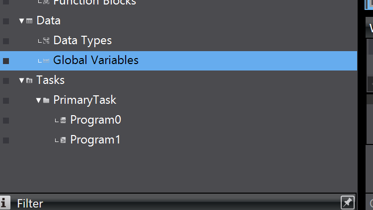
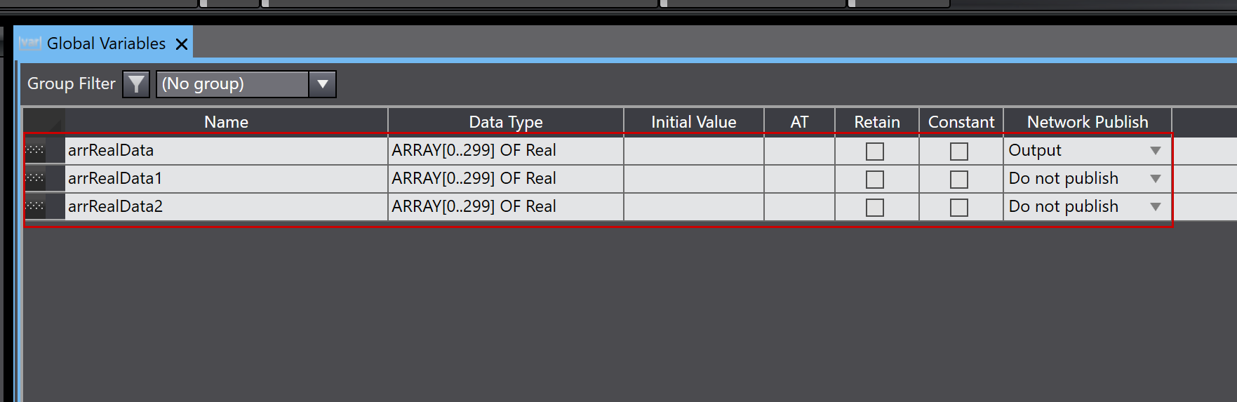
Define the Ethernet/IP tags to connect to the Codesys Runtime.
In this article, we will only use arrRealData, and set Network Publish to “Output” (OMRON NX502-1300 → Codesys Runtime).
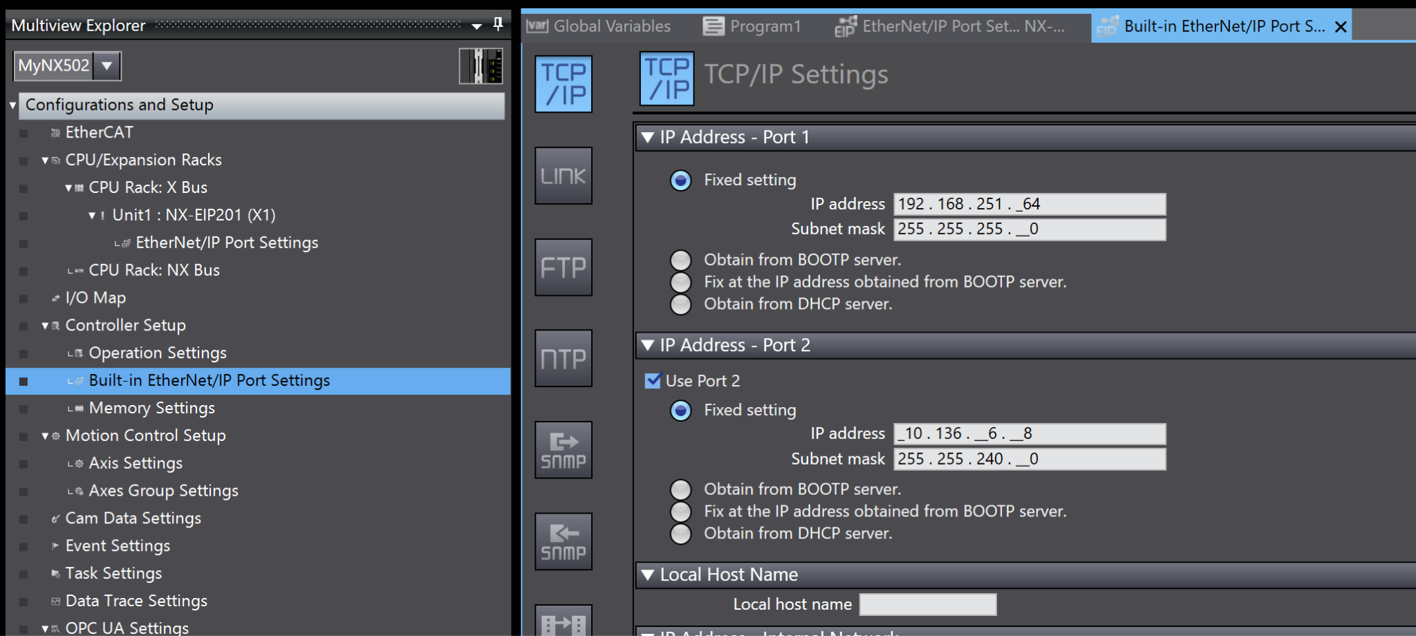
IP Settings
Open Controller Setup→Built-in Ethernet/IP Port Settings and configure the IP address to match your actual network configuration.
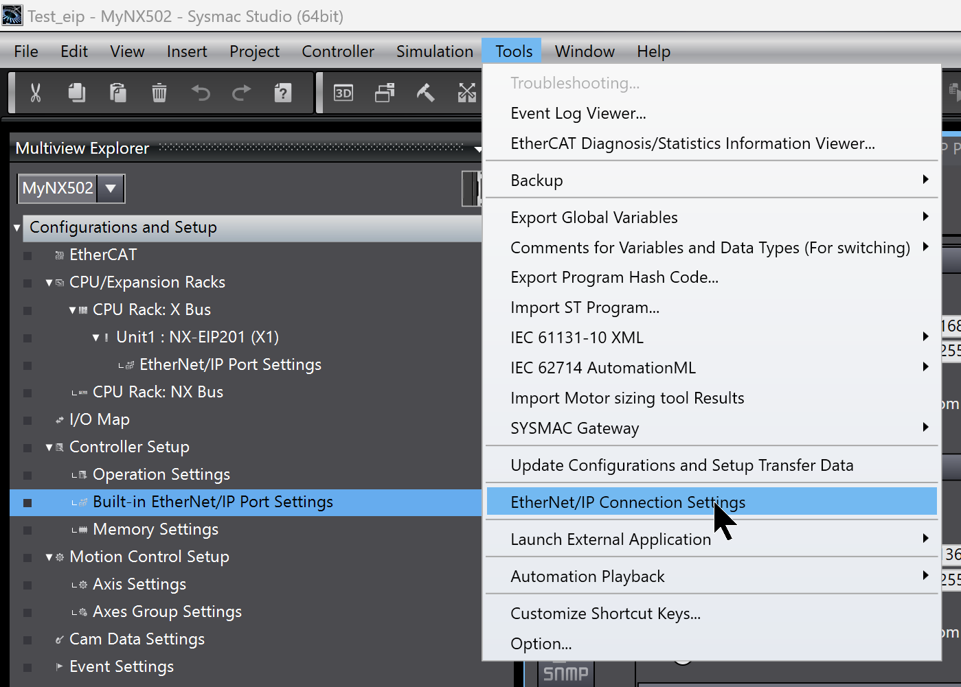
Ethernet/IP Connection Settings
Next, we will establish the Ethernet/IP connection for the NX502-1300. Click Tools → Ethernet/IP Connection Settings.
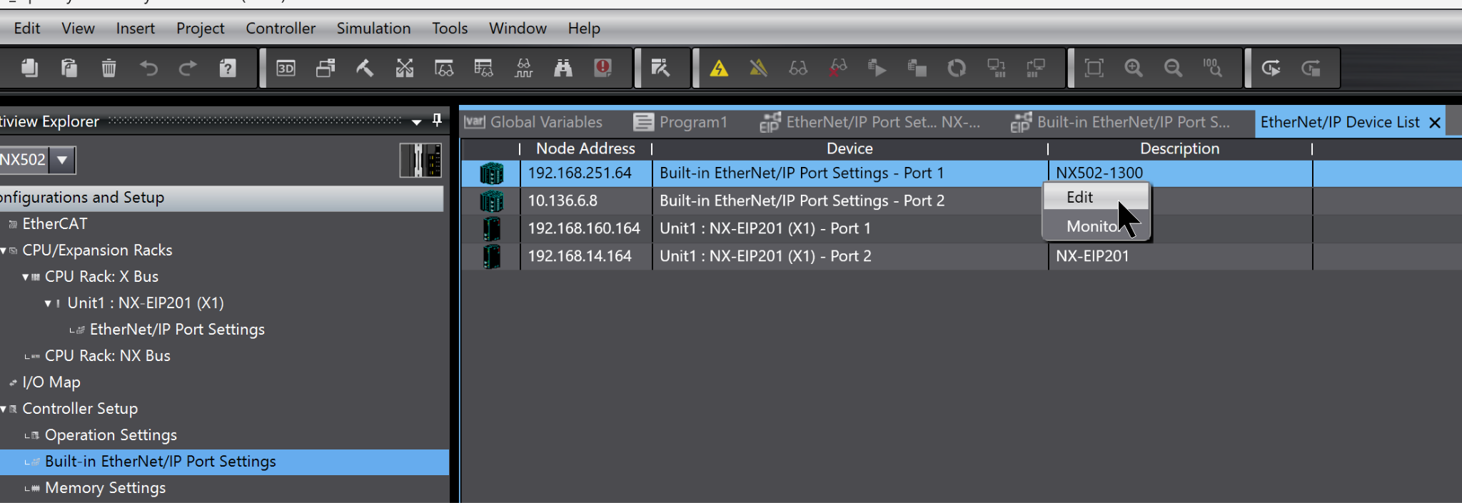
This time, we will use PORT1 of the NX502-1300. Select Port1 → right-click → Edit.
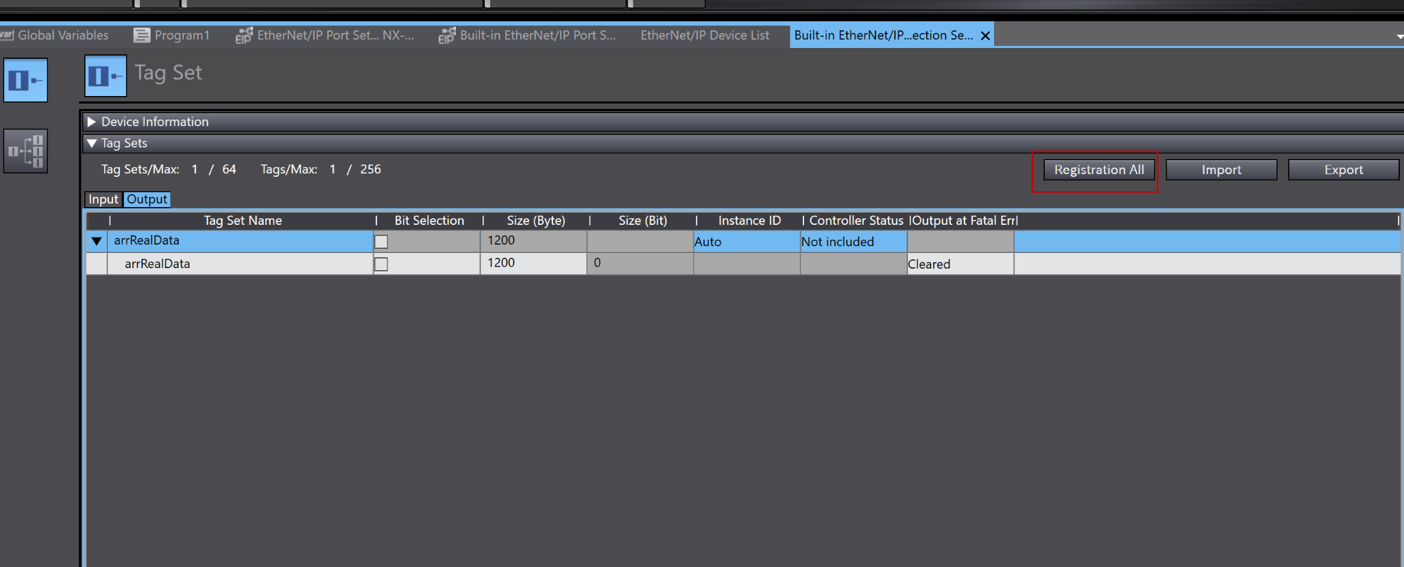
Click “Registration All” to register the Output variable declared earlier as a global variable.
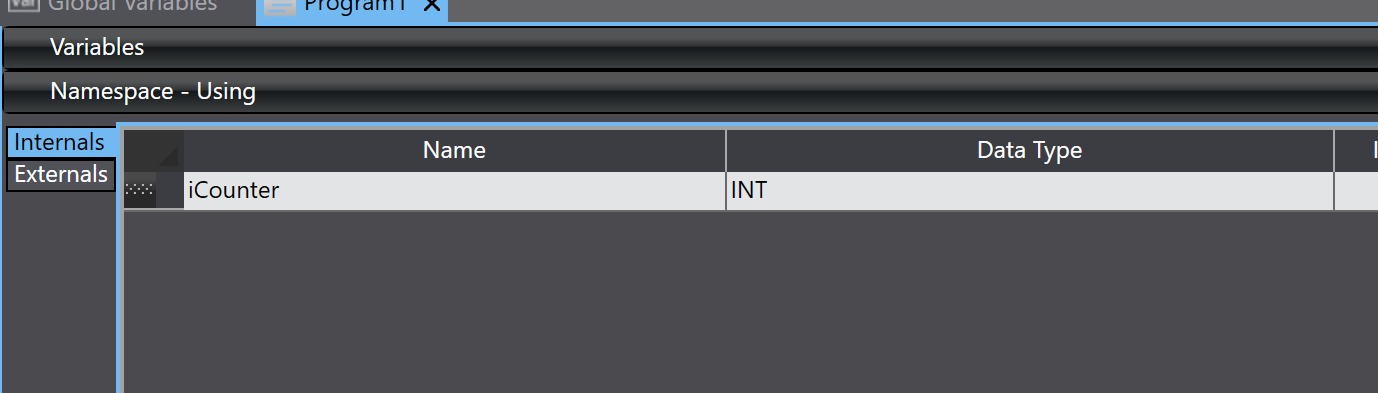
Program
Next, we will create a verification program.
VAR
This defines variables for the FOR Loop.
Code
This program is simulation code that generates eight REAL-type data points.
First, it adds 0.01 to the first element of the array, slowly counting up from 0 to 20. Once it exceeds 20, it resets to 0 and repeats.
Next, in the FOR loop, we set values for the remaining seven elements based on the first value. Each element has an offset of index × 100 added to the first value.
arrRealData[0]:= arrRealData[0]+0.01;
|
|---|
Download
Finally, download the project to the NX502-1300.
Codesys side
Next, we will build the Codesys Runtime side.
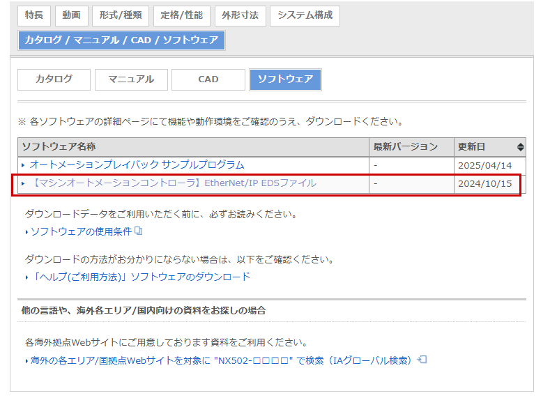
Download the EDS file
Download the EDS file for the NX5 from OMRON’s website.
Install the EDS file
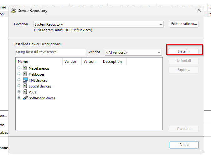
Next, to install the OMRON NX5 EDS file in Codesys, click Tools > Device Repository.
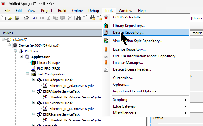
Click Install and install the EDS file downloaded from OMRON’s website.
Add an Ethernet driver
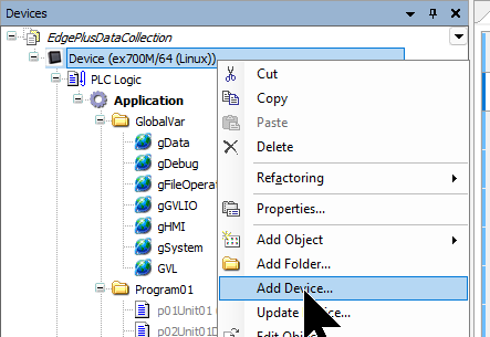
To add an Etherent Driver to your Codesys project, right-click on Device and select Add Device.。
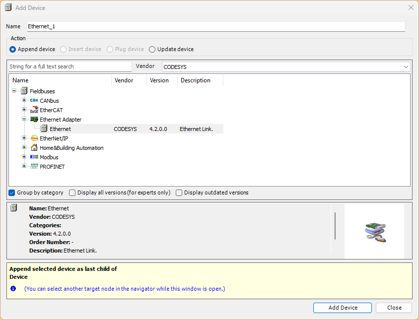
Select Ethernet and add the device.
Add Ethernet/IP Scanner Driver
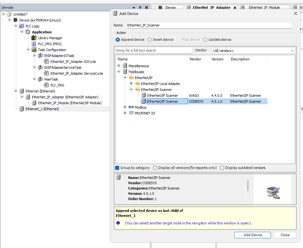
Next, select Ethernet Driver, then right-click > Add Device.
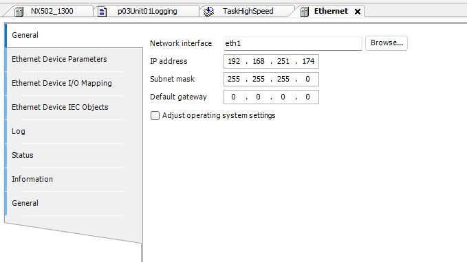
Ethernet Interface Settings
Go to General→Network Interface to configure the Ethernet/IP interface.
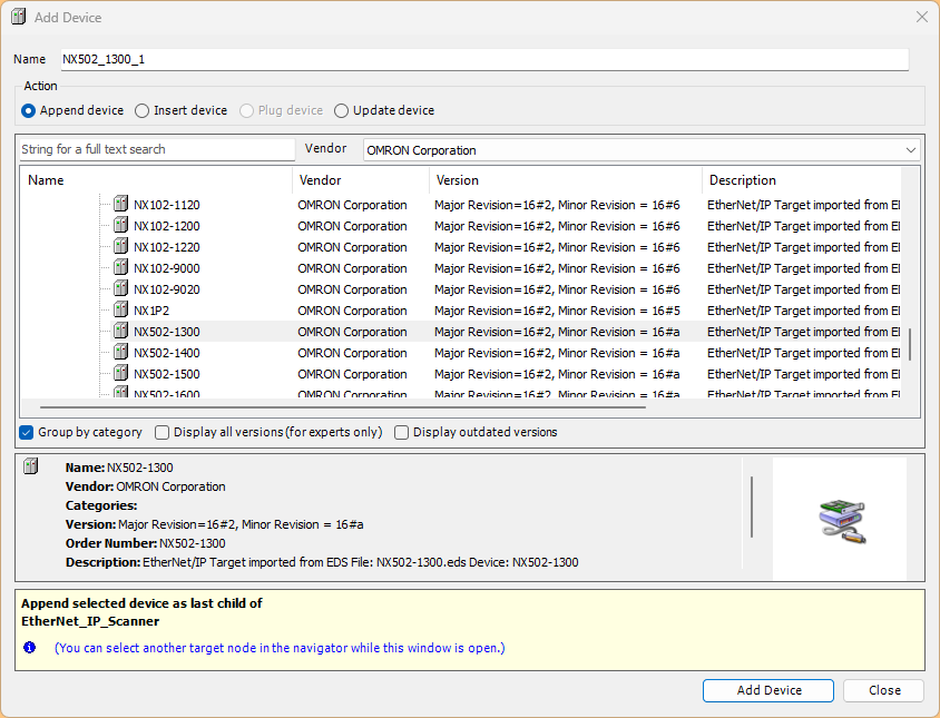
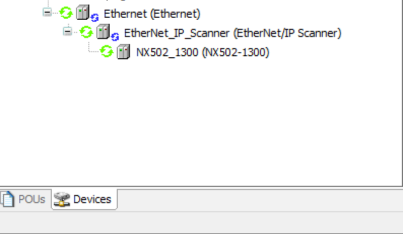
Add NX502-1300
Next, to add the Ethernet/IP connection for OMRON’s NX502-1300, right-click the Ethernet/IP Scanner and select Add Device.
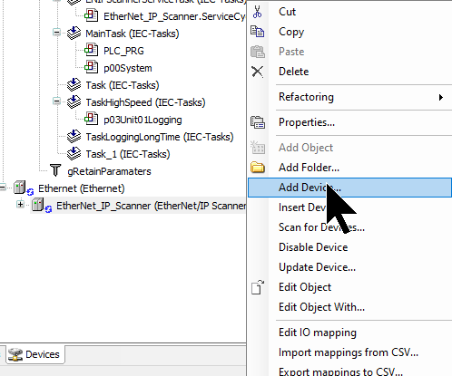
NX502-1300を選択し、Add Deviceで追加します。
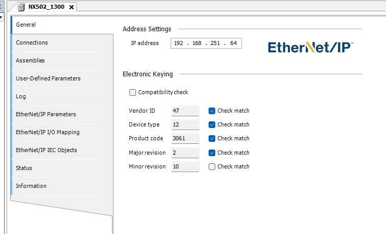
IP Settings
Open the NX502-1300 and configure the IP address to match the actual device.
Ethernet/IP Connection Settings
Next, click Connections → Add Connections to add an Ethernet/IP connection.
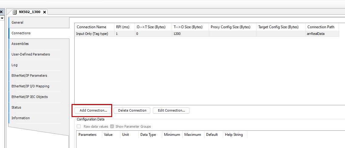
Select Input Only (Tag Type).
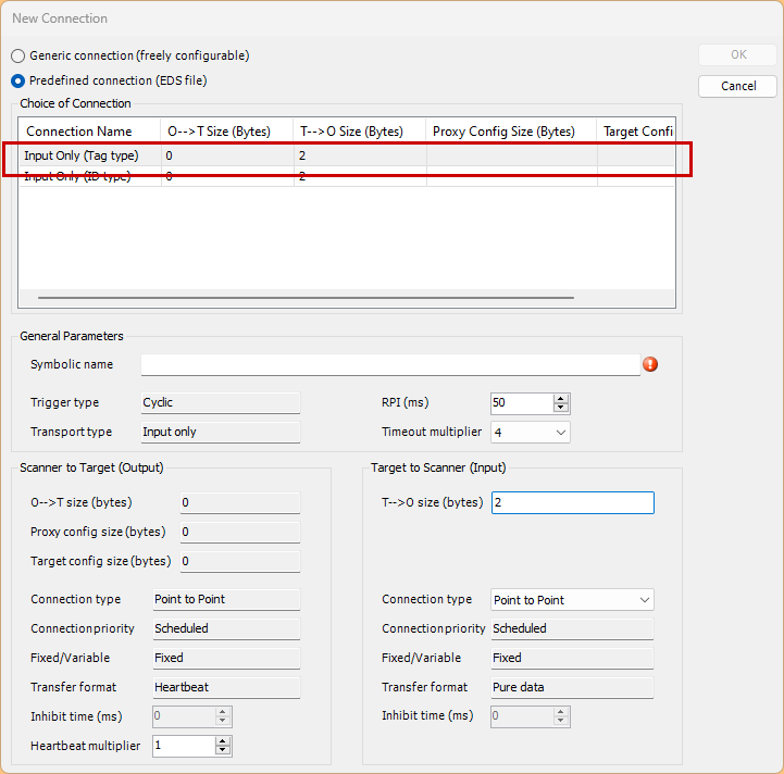
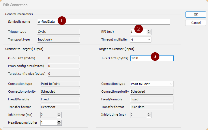
Match the Symbolic Name field to the Output Tags set in Sysmac Studio.
Set PRI according to the actual application.
Match the T→O size to the variable size set in Sysmac Studio.
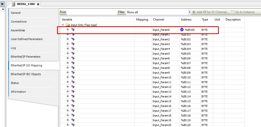
Mapping
Next, perform the mapping. Open the Ethernet/IP I/O Mapping and specify the starting address.In this example, specify %IB100.
Structure
eSystem
This defines system constants using a DINT-type enumeration (ENUM).
iDataTotalLength is set to 2999 as the total data length, and iTotalUnit is set to 7 as the total number of units.
{attribute ‘qualified_only’}
|
|---|
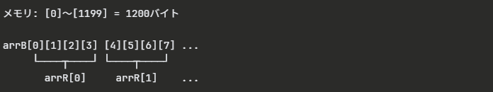
uArray1200Bytes
This is a UNION type definition that allows the same memory area to be accessed as both a BYTE array and a REAL array. It allocates 1200 bytes of memory. When you want to treat it as a BYTE array, access it via arrB; when you want to treat it as a REAL array, access it via arrR. Since REAL is 4 bytes, 1200 ÷ 4 = 300 elements.
TYPE uArray1200Bytes :
|
|---|
stMotorData
This is a structure for storing motor-related data. rCurrentValue is a REAL-type variable holding the current value. arrDataY stores the data history as a 3000-element REAL array using the eSystem.iDataTotalLength (2999) defined earlier.
TYPE stMotorData :
|
|---|
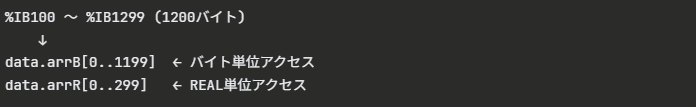
gGVLIO
This is the definition of a global variable that directly maps the UNION type defined earlier to the PLC’s input memory area. AT %IB100 reserves 1200 bytes starting at address 100 in the input byte area. This allows input data from external devices to be accessed as either BYTE or REAL.
{attribute ‘qualified_only’}
|
|---|
gData
This defines global variables for trend graphs and data logging.
arrDataX is an array storing time or index values for the X-axis, containing 3000 elements.
udtMotorDatas is an array containing the previously defined motor data structure for 8 units (0 to 7).
{attribute ‘qualified_only’}
|
|---|
Task
Next, create a task for the logging program.
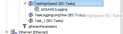
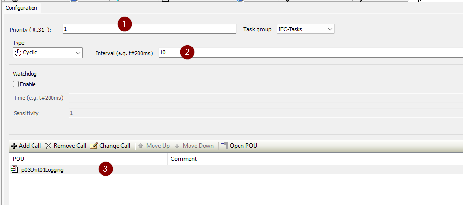
Since the type is Cyclic, the program p03Unit01Logging will run repeatedly every 10 milliseconds. Priority 1 is a relatively high setting, meaning it will be processed before other low-priority tasks.
No. | Item | Setting | Description |
|---|---|---|---|
① | Priority | 1 | Task priority (0 is highest, 31 is lowest) |
② | Interval | 10 | Execution cycle (10ms) |
③ | POU | p03Unit01Logging | Program to execute in this task |
fbLogging
Next, create a function block for logging.
VAR
This is the variable definition section for the function block used for data logging.
FUNCTION_BLOCK fbLogging
|
|---|
Code
This is the execution section of the function block, which records data into an array at the specified interval.
//Start the Logging Period time,Real=>Time
|
|---|
Timer Settings
Since rLogPeriod is in seconds, we multiply by 1000 to convert it to milliseconds.
fbTON2.PT := TO_TIME(rLogPeriod * 1000); |
|---|
Self-reset timer
While xStart is ON, it will continue to generate pulses periodically.
fbTON2(IN := NOT fbTON2.Q AND xStart); |
|---|
Startup Processing (Initialization)
IF fbrtrig.Q THEN
|
|---|
Termination processing (falling edge)
IF fbftrig.Q THEN
|
|---|
Data recording
IF ixlog AND xStart AND iIndex < 2999THEN
|
|---|
Program
The final step is creating the program. This is a management program for logging data from eight motors in parallel, structured to record data simultaneously to each function block.
VAR
This is the variable definition section of the program that manages data logging for eight units.
PROGRAM p03Unit01Logging
|
|---|
Code
This is the main process that logs data for 8 units in parallel.
FOR iLoop :=0 TO eSystem.iTotolUnit DO
|
|---|
Download
Finally, download the project to the Codesys Runtime.
JMobile side
Finally, we will build the JMobile side of EXOR.
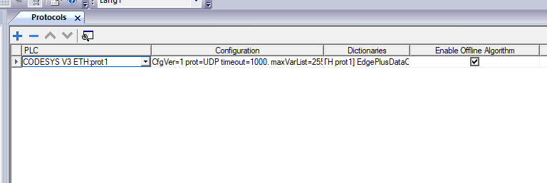
Codesys Connection
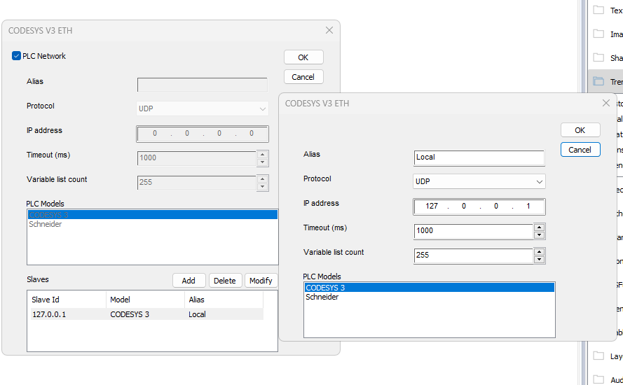
Create a connection for Codesys.
Since you’re only accessing the Codesys Runtime inside the EXOR, the IP address can be 127.0.0.1.
Tag
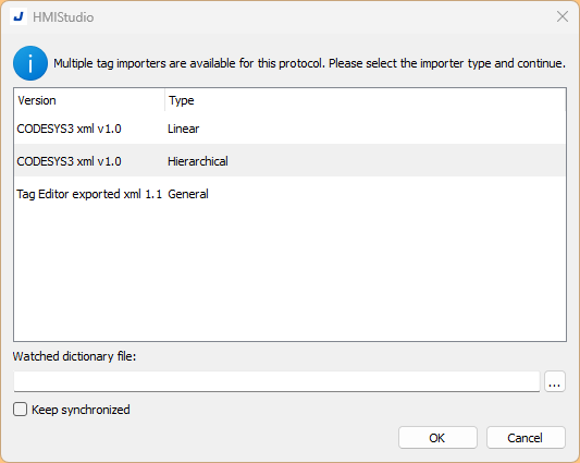
Next, add a Tag to access Codesys. Click the IMPORT button shown in the figure below.
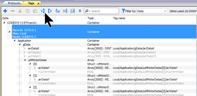
Select Codesys3 XML v1.0 → Proceed by clicking OK.
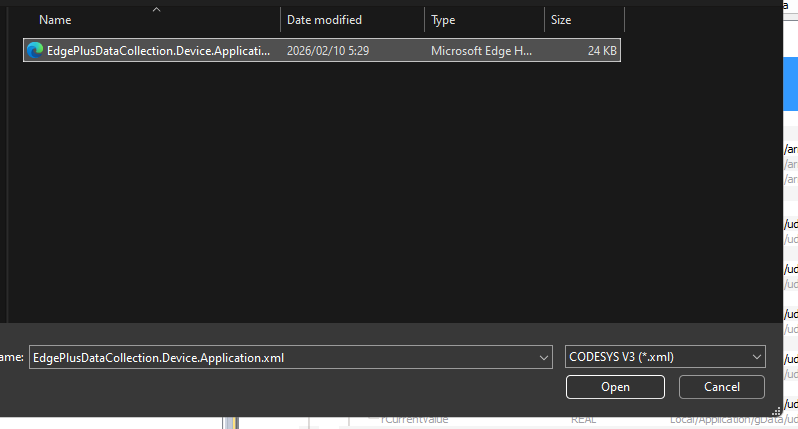
Open the XML file for the Codesys project.
Add the tag shown below.
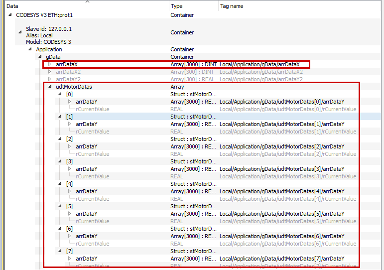
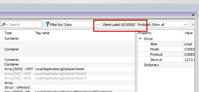
Adding tags to an array in bulk saves on the number of tags used.
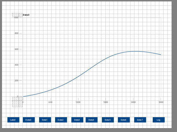
Add Scatter Diagram
Next, add a Scatter Diagram to the screen.
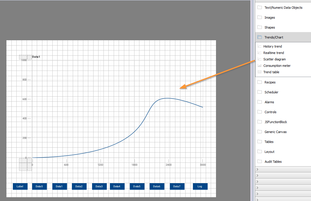
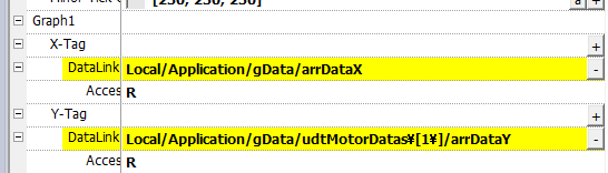
X-Tag/Y-Tag
X-Tag and Y-Tag represent the data for the X/Y axes displayed in the scatter diagram.
Auto-update
Add an event to the scatter diagram to enable automatic updates when array data is updated.
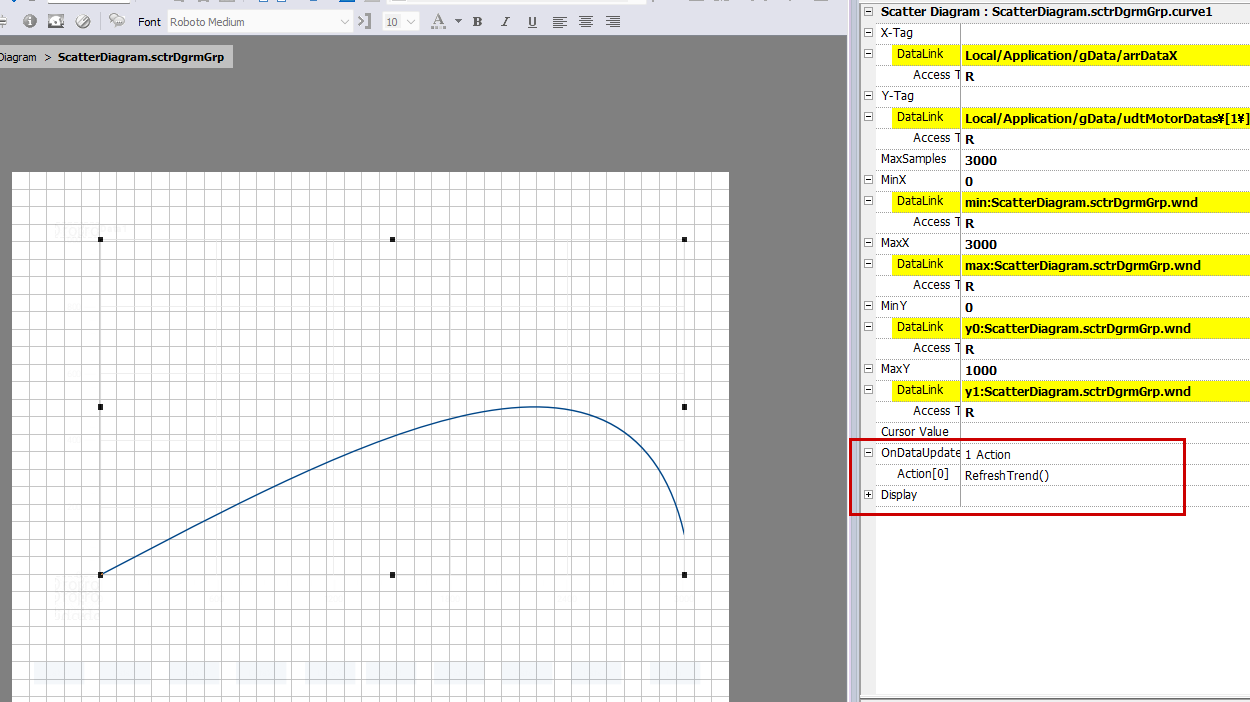
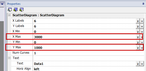
X-Min Y-Min
Set the maximum display values for the X and Y axes of the Scatter Diagram.
Screen
Finally, create the Scatter Diagram screen for Data0-7, spanning 8 pages, and press the Log button to start logging.
Download
Finally, download the project to JMobile Runtime.
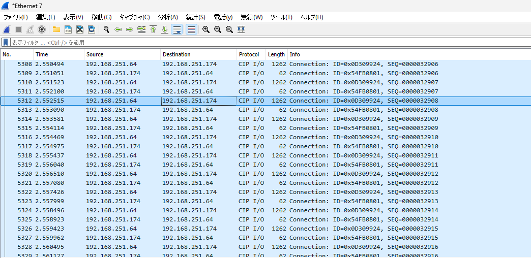
Result
Ethernet/IP communication has been established between Codesys and the NX502-1300.
I was able to confirm this both in Wireshark and within the CIP I/O messages.
You can verify the operation from this video.